Spitznas 2 3055 0010 User manual

Maschinenfabrik GmbH
Spitznas Maschinenfabrik GmbH, Fellerstr.4, D-42555 Velbert, Tel: +49(0)2052 605 0, Fax: +49(0)2052 605 29, www.spitznas.de
Translation of the original manual,
compiled: 14.02.11 230550010_en_Version_01 Page 1 of 16
Hydraulic
Drill
Type 2 3055 0010
Illustration can differ from the original
Operation and
Maintenance Manual

Hydraulic Drill
2 3055 0010
Maschinenfabrik GmbH
Spitznas Maschinenfabrik GmbH, Fellerstr.4, D-42555 Velbert, Tel: +49(0)2052 605 0, Fax: +49(0)2052 605 29
, www.spitznas.de
Translation of the original manual,
compiled: 14.02.11 230550010_en_Version_01 Page 2 of 16
TECHNICAL SPECIFICATION
Drill Holder MK 3
Nominal Pressure 140 bar
Free speed / Speed under load 280/ 230 1/min
Torque 60 Nm at
150 bar and 280 1/ min
Fluid Hydraulic oil
Weight 8.5 kg
Connection/ Quick-lock coupling M 18 x 1.5
ID of hose DN10
Oil filtering ISO-Purity Degree 18/13
Power 1.6 kW
Noise level at 1 m distance 85.2 db(A)
Vibration level
Sand-lime brick
Medium hard concrete
3.4 m/s²
15.8 m/s²

Hydraulic Drill
2 3055 0010
Maschinenfabrik GmbH
Spitznas Maschinenfabrik GmbH, Fellerstr.4, D-42555 Velbert, Tel: +49(0)2052 605 0, Fax: +49(0)2052 605 29
, www.spitznas.de
Translation of the original manual,
compiled: 14.02.11 230550010_en_Version_01 Page 3 of 16
SAFETY INSTRUCTIONS
ATTENION: Your own safety and the safety of the people near by depend on the careful and
appropriate operation of the drill. Before using it, make yourself familiar with the operation of the
drill and remove unnecessary people from the work area. Read all operation and maintenance
instructions before starting the operation. The drill is designed for special applications only.
We therefore thoroughly recommend not modifying and/ or using it for improper applications.
Before operating the drill, make yourself familiar with the following safety instructions:
1. Keep the work area clean and uncluttered.
2. Keep children away from the drill or the work area.
3. Proper Clothing
Do not wear clothes, which are too tight or too loose. This can constrain your movement,
resp. can be caught by the drill. This applies for jewellery as well.
4. Protect your head and hear, eyes and ears, hands and feet.
Wear a helmet, goggles and ear protection. Protect your hands with non-slipping gloves.
Safety shoes protect your feet. Disconnect the machine from the main supply after finishing
the work (avoidance of unexpected starting in uncontrolled condition).
5. Switch off the machine before laying it aside (shut valve). Disconnect machine from
power supply after finishing the work (avoid unintentional starting).
6. Stay alert
Fatigue leads to carelessness and accidents. Never work under the influence of alcohol,
drugs or stronger medication.
7. Safe working
If the drill rod jams, the torque rises immediately. Always be prepared fort his and hold the
handles tight. Ensure safe foothold and good balance.
The machine is operated by hand and stops at a torque of approx. 40- 45 Nm.
8. Avoid unintended starting
Never carry the drill with the motor running.
9. Follow the general current and appropriate Accident Prevention and Safety
Procedures.
10. Storage
At longer down times (a few days) rinse the motor with hydraulic oil.

Hydraulic Drill
2 3055 0010
Maschinenfabrik GmbH
Spitznas Maschinenfabrik GmbH, Fellerstr.4, D-42555 Velbert, Tel: +49(0)2052 605 0, Fax: +49(0)2052 605 29
, www.spitznas.de
Translation of the original manual,
compiled: 14.02.11 230550010_en_Version_01 Page 4 of 16
OPERATION INSTRUCTIONS
The capacity of the machine is designed for a diameter of 48 mm and a depth of 12 m in coal and
stone with medium hardness.
The drill is operated with hydraulic oil. When feeding the drill from the system, it must be
considered that the machine is not operated at a bigger pressure as specified.
Pressure reducing valves have to be applied, otherwise the machine will be damaged or
destructed.
Fig. 2 Main Elements
1. Handle
2. Drive
3. Actuating Lever
4. Pressure supply „P”
5. Tank connection „T”
6. Overload valve
7. Drill holder
Connect the machine to the main supply according to fig. 3. Install the main valve (Fig. 3, item 7) in
the supply line, this allows locking the supply, e. g. when the system is modified.
Fig. 3 Switch Diagram
1. Drive
2. Actuating Lever
3. Return Valve
4. Overload Valve
5. Screen
6. Quick-lock coupling
7. Pressure hose
8. Tank hose
9, 10 Cut off cock
3
7
2
1
6 4
5

Hydraulic Drill
2 3055 0010
Maschinenfabrik GmbH
Spitznas Maschinenfabrik GmbH, Fellerstr.4, D-42555 Velbert, Tel: +49(0)2052 605 0, Fax: +49(0)2052 605 29
, www.spitznas.de
Translation of the original manual,
compiled: 14.02.11 230550010_en_Version_01 Page 5 of 16
Drilling
•Install the tool at the machine.
•Hydraulic lines. Attention: Pay attention to the correct order of the hoses.
First tank hose “T” (see switch diagram fig. 2).
•Cool the drill with water
•Actuate valve and start the drill-/ reaming up work.
After finishing the drill work
•Release actuating lever (2)
•Shut main valve (9), shortly press actuating lever (2), release rest pressure and
disconnect hoses. First pressure hose „P“ – fig. 3.
•Take out drill tool.
•Clean retainer seat
Maintenance
Keep the tool clean
•Only regular maintenance ensures a constant capacity of the tool.
•During the use of the hydraulic drill pay attention ot the following:
oCleanness of the oil.
oAppropriate dirt protection of the lines and the connections of the drill.
oClean the drill after each job and protect it against corrosion with a light protection
oil.
oAt longer down time (a few days), rinse the drive with hydraulic oil.
Pressure Connection „P”
Tank Connection „T”

Hydraulic Drill
2 3055 0010
Maschinenfabrik GmbH
Spitznas Maschinenfabrik GmbH, Fellerstr.4, D-42555 Velbert, Tel: +49(0)2052 605 0, Fax: +49(0)2052 605 29
, www.spitznas.de
Translation of the original manual,
compiled: 14.02.11 230550010_en_Version_01 Page 6 of 16
MAINTENANCE OF HYDRAULIC TOOLS
Only proper maintenance can ensure
constant performance, reduction in wear
and thus, a decrease in operating costs
and an increase in service life.
Our hydraulic tools are equipped for an
operating pressure of up to 100 bar.
Regulator setting for a lower operating
pressure is possible.
The tools should not run empty, because
this results in heat and higher wear of the
output section and the tool holder.
The hydraulic oil should be clean. This is
ensured by professional equipment.
Clean the connecting parts before
connecting the hydraulic hoses.
For an economic use of the hydraulic
tools the required sizes of pipe, fittings
and hoses have to be adjusted.
Proper greasing of the gear and the tool
heads is a must. See the operation
manual on this.
After finishing the work the tools have to
be cleaned and protected against
corrosion.
Visible grease nipples are provided for
regular lubrication of the gears with a
grease gun, or the gearboxes have a
long term greasing.
Note the following for grease lubrication:
Every 60 hours of operation check
striking mechanism, friction bearings and
antifriction bearings; if necessary, grease
them. Every 300 hours of operation
grease the gears and antifriction
bearings anew. In the case of impact
wrenches, use a grease gun to grease
the anvil guide before beginning daily
work, or every 6-8 hours.
All inner parts of the drive (tool holder
must be lubricated before storing for
longer periods of time in order to prevent
rusting. It is recommended to check the
vanes and bearings at regular intervals.
Store tools in dry rooms only.
Grease to be used:
In general: SAE 5 W to SAE 10
For impact wrenches without gear only SAE 5 W
For saw chain greasing on chain saws:
Machine oil with adhesive additive, viscosity:
c ST 49-55’ (6,5-7,5 E)/ 50°C
- Examples-
GREASE (free of acids and resins) Multi-purpose greases for antifriction
and friction bearings and gears Special greases for high-speed miter gears
Designation in accord. with DIN 51502
Consistency class (DIN 51818)
Saponification type
Dripping point
Worked penetration
Temperature range
K L 2 k
2
Lithium
185 °C
265 to 295
-25°C to + 125°C
G 000 h
00
Sodium
145°C
400 bis 410
-25°C bis + 100°C
For the operation of the hydraulic motor we recommend high-class hydraulic oil, e. g. HLP 46,
depending on the case of operation (temperature).

Hydraulic Drill
2 3055 0010
Maschinenfabrik GmbH
Spitznas Maschinenfabrik GmbH, Fellerstr.4, D-42555 Velbert, Tel: +49(0)2052 605 0, Fax: +49(0)2052 605 29
, www.spitznas.de
Translation of the original manual,
compiled: 14.02.11 230550010_en_Version_01 Page 7 of 16
Spare Parts and Accessories
Only original spare parts may be used. There is no warranty for damages and liability is
disclaimed, if non-original spare parts and accessories are used.
The repairing of the machine is allowed authorized expert companies only.
Problem, Cause, Remedy
Problem Cause Remedy
The drilling is not satisfactory,
though the motor is running
properly.
•Pressure of oil too low
•dull drill rod
•Screen at pressure supply
clogged
•Check supply unit
•Replace drill rod (new)
•Clean the screen
Drill doesn’t start •Connections mixed-up
•Screen at pressure supply
clogged
•Connect correctly
•Clean the screen

Hydraulic Drill
2 3055 0010
Maschinenfabrik GmbH
Spitznas Maschinenfabrik GmbH, Fellerstr.4, D-42555 Velbert, Tel: +49(0)2052 605 0, Fax: +49(0)2052 605 29
, www.spitznas.de
Translation of the original manual,
compiled: 14.02.11 230550010_en_Version_01 Page 8 of 16
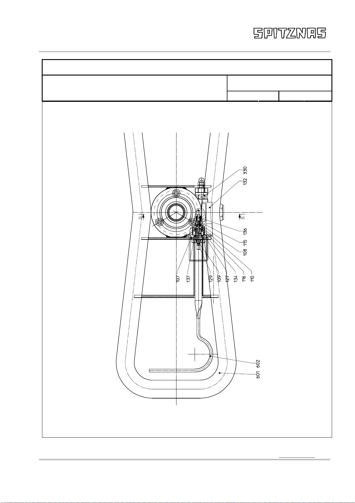
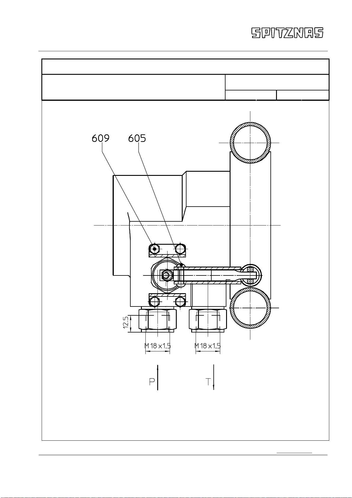
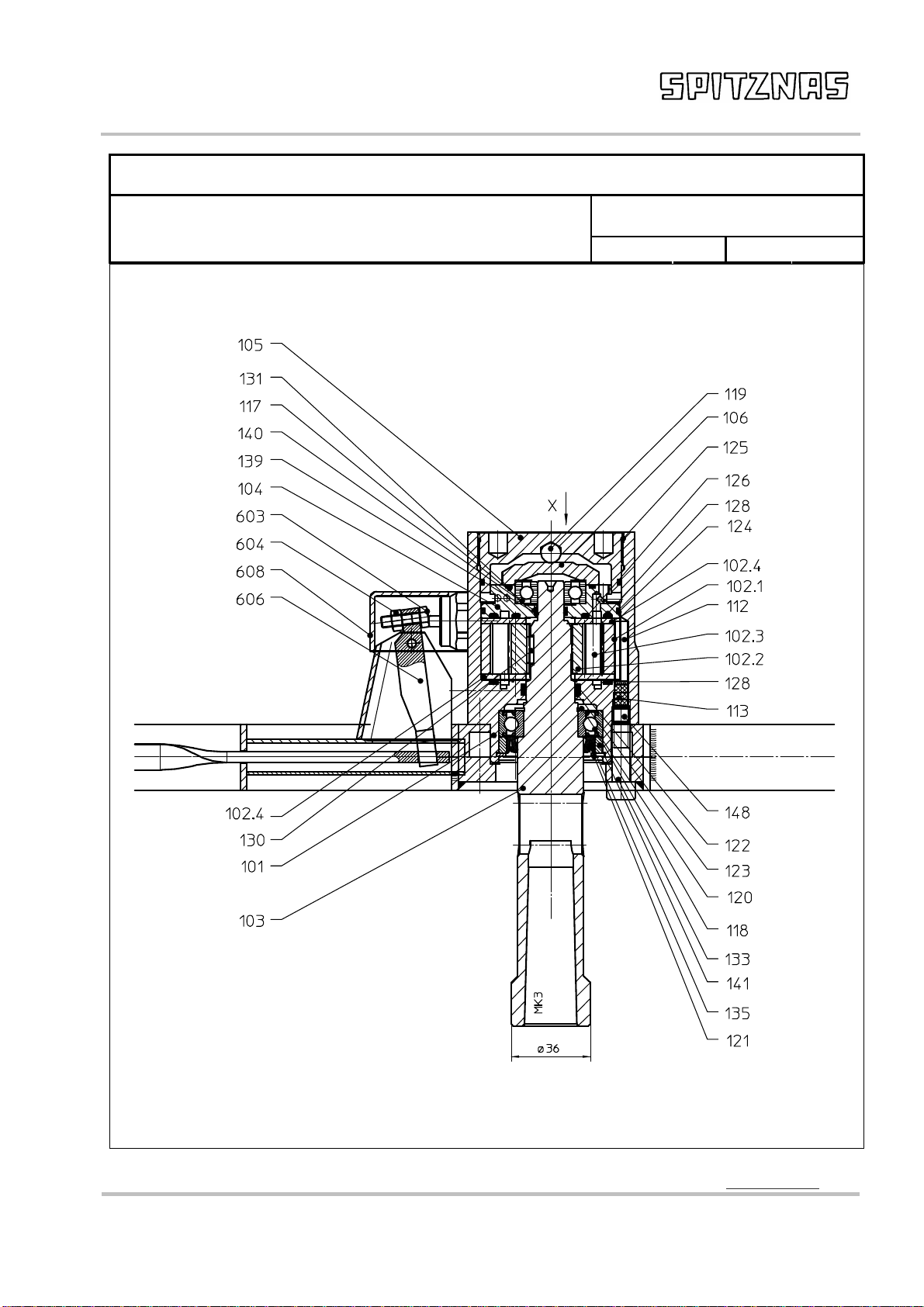
Spare Parts List
Description: Part and drawing number:
2 3055 0010
Hydraulic Drill
Item
Qty.
Description Part and
drawing no. Remarks
101
1 Motor housing 2 3053 1010
102
1 Drive 5 6075 1990
102.1
1 Rim of the gear 5 6075 1020
102.2
1 Rotor 5 6075 1030
102.3
10 Sprocket 5 6075 1050
102.4
2 Control plate 5 6075 1150
103
1 Drive shaft 2 3053 1040
104
1 End plate 2 3053 1120
105
1 Pressure screw 5 6075 1130
106
1 Pressure plate 2 3051 1140
107
1 Locking screw 2 3051 3050
108
1 Valve seat 5 6067 3070
109
1 Valve piston, Assy. 5 6067 3040
110
1 Pressure piece 5 6067 3020
112
1 Pin 5 6067 1160
113
1 Plug 5 6067 1170
114
2 Connecting nipple 2 3055 3810
115
1 Valve plate 2 3051 3140
116
1 O-Ring 9 1901 2340
117
1 Grooved ball bearing 9 1004 0450
118
1 Grooved ball bearing 9 1003 0520
119
1 Steel ball 9 1017 0060
120
1 Snap ring 9 1702 0140
121
1 Snap ring 9 1703 0150
122
1 O-Ring 9 1921 5080
123
1 Supporting ring 9 1919 0230
124
2 O-ring 9 1901 3610
125
1 O-ring 9 1921 1570
126
1 O-ring 9 1901 3280
127
1 O-ring 9 1921 6000
128
2 O-ring 9 1921 2640
129
1 O-ring 9 1901 2080
130
6 Bearing needle 9 1019 0170
131
1 O-ring 9 1901 3500

Hydraulic Drill
2 3055 0010
Maschinenfabrik GmbH
Spitznas Maschinenfabrik GmbH, Fellerstr.4, D-42555 Velbert, Tel: +49(0)2052 605 0, Fax: +49(0)2052 605 29
, www.spitznas.de
Translation of the original manual,
compiled: 14.02.11 230550010_en_Version_01 Page 9 of 16
Spare Parts List
Description: Part and drawing number:
2 3055 0010
Hydraulic Drill
Item
Qty.
Description Part and
drawing no. Remarks
132
1 Locking screw 9 1174 0010
133
3 Fillister-head screw 9 1110 5100
134
1 O-ring 9 1901 2560
135
1 Radial shaft sealing ring 9 1905 0080
136
1 Pressure spring 9 1803 5130
137
1 O-ring 9 1901 3450
138
1 Water screen 5 6067 5010
139
1 O-ring 9 1901 3020
140
1 Supporting ring for o-ring 9 1919 0390
330
1 Pressure limiting valve 2 3051 3300 Pos. 331-346
331
1 Valve housing 2 3051 3310
332
1 Screw 2 3051 3320
333
1 Pressure pin 2 3051 3330
334
1 Spring plate, Assy. 2 3051 3340
336
1 Slide 2 3051 3360
337
1 Nut 9 1208 0080
338
1 Adjusting screw 9 1147 4080
339
1 Hexagonal nut 9 1203 0040
340
1 Pressure spring 9 1803 5000
341
1 O-ring 9 1901 3410
342
1 O-ring 9 1921 1450
343
1 Supporting ring for o-ring 9 1919 0300
344
1 O-ring 9 1901 2780
345
1 O-ring 9 1901 2560
346
1 Supporting ring for o-ring 9 1919 0280
141
1 Spacing ring 2 3053 1080
142
1 Guide bushing 2 3052 3850
143
1 Valve plate 2 3052 3860
144
1 Valve seat 2 3052 3870
145
1 O-ring 9 1901 2400
146
1 Pressure spring 9 1803 2640
148
1 Thread pin 9 1140 5010
149
2 Snap ring 9 1914 0260

Hydraulic Drill
2 3055 0010
Maschinenfabrik GmbH
Spitznas Maschinenfabrik GmbH, Fellerstr.4, D-42555 Velbert, Tel: +49(0)2052 605 0, Fax: +49(0)2052 605 29
, www.spitznas.de
Translation of the original manual,
compiled: 14.02.11 230550010_en_Version_01 Page 10 of 16
Spare Parts List
Description: Part and drawing number:
2 3055 0010
Hydraulic Drill
Item
Qty.
Description Part and
drawing no. Remarks
601
1 Handle, assy. 2 3053 6010
602
1 Tension rod 2 3053 6090
603
1 Hexagonal screw 9 1107 3080
604
1 Hexagonal nut 9 1209 0070
605
1 Half-round rivet 9 1603 0150
606
1 Valve lever 2 3053 6100
608
1 Protection 2 3053 6110
609
4 Fillister-head screw 9 1107 2010

Hydraulic Drill
2 3055 0010
Maschinenfabrik GmbH
Spitznas Maschinenfabrik GmbH, Fellerstr.4, D-42555 Velbert, Tel: +49(0)2052 605 0, Fax: +49(0)2052 605 29
, www.spitznas.de
Translation of the original manual,
compiled: 14.02.11 230550010_en_Version_01 Page 11 of 16
Spare Parts List
Description: Part and drawing number:
2 3055 0010
Hydraulic Drill
Hydraulic Drill
2 3055 0010
Maschinenfabrik GmbH
Spitznas Maschinenfabrik GmbH, Fellerstr.4, D-42555 Velbert, Tel: +49(0)2052 605 0, Fax: +49(0)2052 605 29
, www.spitznas.de
Translation of the original manual,
compiled: 14.02.11 230550010_en_Version_01 Page 12 of 16
Spare Parts List
Description: Part and drawing number:
2 3055 0010
Hydraulic Drill
Hydraulic Drill
2 3055 0010
Maschinenfabrik GmbH
Spitznas Maschinenfabrik GmbH, Fellerstr.4, D-42555 Velbert, Tel: +49(0)2052 605 0, Fax: +49(0)2052 605 29
, www.spitznas.de
Translation of the original manual,
compiled: 14.02.11 230550010_en_Version_01 Page 13 of 16
Spare Parts List
Benennung: Part and drawing number:
2 3055 0010
Hydraulic Drill
Hydraulic Drill
2 3055 0010
Maschinenfabrik GmbH
Spitznas Maschinenfabrik GmbH, Fellerstr.4, D-42555 Velbert, Tel: +49(0)2052 605 0, Fax: +49(0)2052 605 29
, www.spitznas.de
Translation of the original manual,
compiled: 14.02.11 230550010_en_Version_01 Page 14 of 16
Spare Parts List
Benennung: Part and drawing number:
2 3055 0010
Hydraulic Drill

Hydraulic Drill
2 3055 0010
Maschinenfabrik GmbH
Spitznas Maschinenfabrik GmbH, Fellerstr.4, D-42555 Velbert, Tel: +49(0)2052 605 0, Fax: +49(0)2052 605 29
, www.spitznas.de
Translation of the original manual,
compiled: 14.02.11 230550010_en_Version_01 Page 15 of 16
Spare Parts List
Benennung: Part and drawing number:
2 3055 0010
Hydraulic Drill
Item 331 – 346 Pressure Limiting Valve

Hydraulic Drill
2 3055 0010
Maschinenfabrik GmbH
Spitznas Maschinenfabrik GmbH, Fellerstr.4, D-42555 Velbert, Tel: +49(0)2052 605 0, Fax: +49(0)2052 605 29
, www.spitznas.de
Translation of the original manual,
compiled: 14.02.11 230550010_en_Version_01 Page 16 of 16
D e c l a r a t i o n o f C o n f o r m i t y
as defined in the European Union Machine Directive 2006/42/ EC
for usable machines
We, the company
SPITZNAS Maschinenfabrik GmbH, Fellerstraße 4, 42555 Velbert– Langenberg,
declare that the following product
Description: Hydraulic Drill
Model 2 3055 0010
complies with the provisions of the European Union Machine Directive 2006/42/ EC,
and conforms to the following standards or standardized documents:
DIN EN ISO 12100
DIN 24063
Name of the authorized person for documentation: Mr. Wolfgang Klare
Address of the authorized person for documentation: see manufacturer’s address
42555 Velbert, 24.11.10
Table of contents
Other Spitznas Drill manuals


