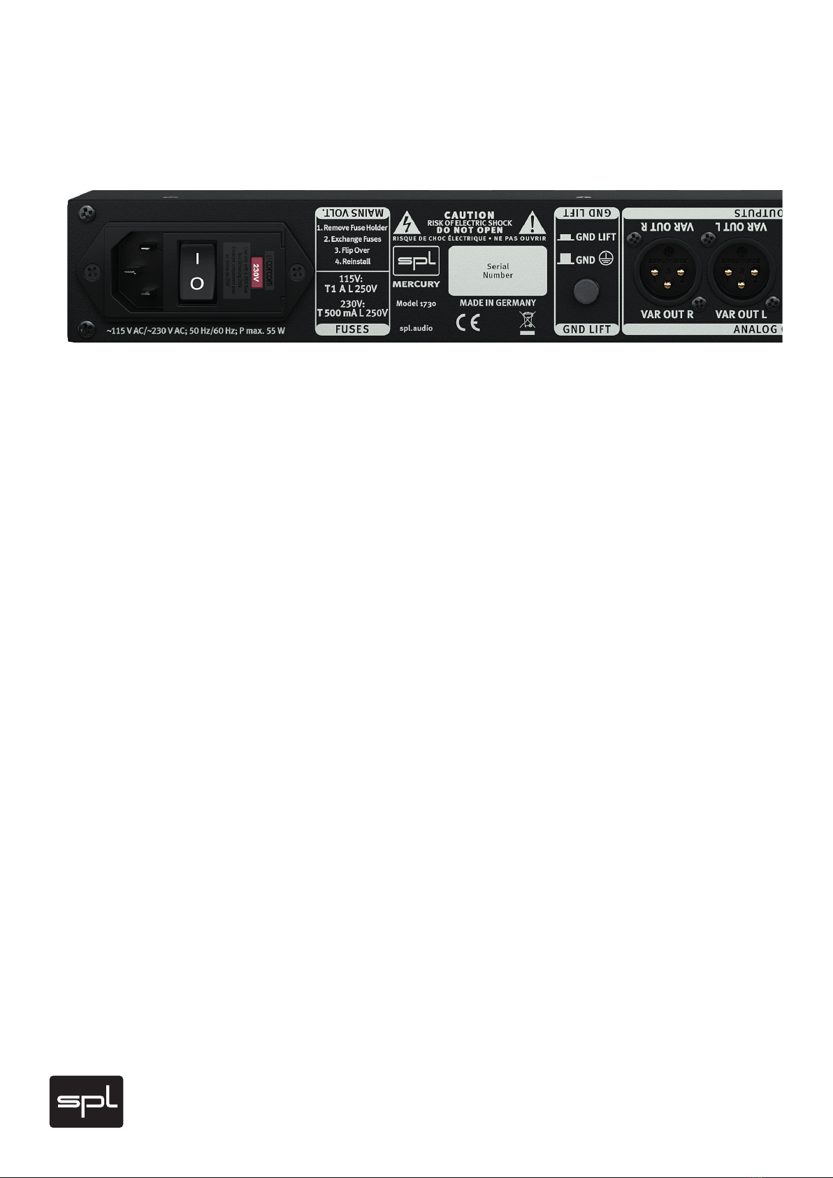
SPL Mercury User manual

Mercury
Mastering D/A-Converter
Manual

Content
Mercury
Version 1.0 – 01/2020 2
Package Contents 2
Product Registration 2
Introduction 3
Mastering D/A Converter in 120V Technology 3
Technical Aspects 4
120 Volt Technology 4
DLP120 4
120 Volt Technology – Diagram 5
Installation 6
Voltage Selection 6
First Steps 6
Cabling: Rear Side 7
XLR inputs and output 7
Graphic/Overview 8
Ground Lift switch to avoid ground loop 10
USB 10
Optical 1 and Optical 2 (TOSLINK) 10
Coaxial 1 and Coaxial 2 (S/P-DIF) 10
AES 1 10
AES 2 [DW L and DW R] 11
Word Clock 11
FIX OUT 11
VAR OUT 11

Content
Control Elements 12
Graphic/Overview 12
USB 14
AES 1 14
AES 2 14
Coax 1 14
Coax 2 14
Opt 1 14
Opt 2 14
Mute 14
Sync 15
Display 15
Output 15
Specications 16
Measurements 16
Security Advices 17
Notes on Environmental Protection 18
Contact 19

2
Version 1.0 – 01/2020
Developer: Bastian Neu
This manual includes a description of the product but no guarantee as for specific charac-
teristics or successful results.
Unless stated otherwise, everything herein corresponds to the technical status at the
time of delivery of the product and user manual by SPL electronics GmbH.
The design and circuitry are under continuous development and improvement.
Technical specifications are subject to change.
Package Contents
Mercury Mastering D/A Converter
Power cord
USB cable
Manual
The Mercury Mastering D/A Converter is available in three different color combinations.
Black: Model 1730
Red: Model 1734
All Black: Model 1733
Do consider keeping the original packaging. It can come in very useful whenever you need
to transport your gear. If there is ever the need to send it in for repair, the original packag-
ing guarantees a safe shipment.
Product Registration
Register your device to get useful information concerning the product. On the front page
of this manual you will find a QR code, which includes the link to the registration form and
automatically fills in the serial number and product name into the form. Alternatively you
can also call up the online form with your internet browser via the following link:
https://spl.audio/register

3
Introduction
Mastering D/AConverter in 120V Technology
The Mercury Mastering D/A Converter perfectly connects the SPL Mastering Universe to
the digital world.
Mercuryisastereodigitaltoanalogconverterthatfulllsthehighestdemandsbothtech-
nologically and tonally.
Mercury provides connections for a total of seven digital stereo input sources.
It provides an USB input, two coaxial, two optical and two AES/EBU inputs – the AES
Input 2 also supports Dual-Wire (DW) mode.
Each digital sources has its dedicated and illuminated switch for instant selection and
fast comparison.
Themandatorylow-pass ltersthat immediatelyfollowtheDAconverter’sanalogout-
putarebuiltin120Vrailtechnology.TheltersareeachoptimizedforPCMandforDSD
playback.
WerefertothemasDLP120,whichstandsforduallow-passltersin120Vtechnology.
DLP120 signicantly increases the dynamic range and headroom beyond the current
benchmarks.
ConversionisdesignedaroundAKM’shighlyacclaimedVelvet-Sound®convertertech-
nologythatsportssamplingratesofupto768kHz,32bitandDirectStreamDigitalupto
DSD4.
Mercuryprovidestwosetsofanalogstereooutputs.Oneofwhichisxedandcanbecali-
brated to all common reference levels, the other provides an analog controllable output
level, which makes Mercury a state-of-the-art monitor controller as well.
The SPL Mercury Mastering D/A Converter was developed and manufactured in Germany.

4
Technical Aspects
120 Volt Technology
SPL‘s goal was to push analog signal processing to the limits. That‘s why we combined
thebestpossiblecomponentswithahigh-gradeoptimizedcircuitdesign.
We have been using the in-house developed 120 Volt technology - the highest-ever oper-
ating voltage used for audio applications - in all our products from the Mastering series
for years. Some of the most highly respected Mastering studios today revolve around
SPL consoles and signal processors from our Mastering series (Bob Ludwigs Gateway
Mastering & DVD in the USA, Simon Heyworth‘s Super Audio Mastering in the UK, Galaxy
Studios in Belgium, and the legendary Wisseloord in the Netherlands, for instance).
The 120 Volt technology is based on op-amps developed internally by SPL‘s co-founder
and Chief Developer Wolfgang Neumann. The Hermes Mastering Router features the
most advanced generation of these op-amps. They boast with even better tech specs
thankstothethermalbehavioroptimizationtheyunderwentunderthehandsofBastian
Neu.
Ultimately, the supply voltage is key for the overall dynamic response of a processor.
Voltage is to an electrical circuit what cylinder capacity is to an internal combustion
engine:
You can‘t replace cylinder capacity with anything else, except more cylinder capacity.
DLP120
Another technological speciality of the Mercury is the DLP120.
The output signal of a DAC-IC must always be filtered with a low-pass filter.
This is done digitally on the chip in most DACs. Followed by the analog signal processing
stage. This analog circuit is typically operated with the same voltage as the DAC-IC, for
example 5V. The first stage that the analog signal finds is therefore a dynamic range
and signal-to-noise ratio, which is limited by this voltage. The Mercury uses the DLP120
insteadofthisstandardtechnology.DLPstandsfor“DualLowPass”.That’stwoseparate
analog filters in 120V technology. Depending on the type of digital signal, the analog sig-
nal passes through the PCM or DSD filter and unfolds freely into a huge dynamic range.
The complete processing stage operates with a voltage of +-60V.

5
Technical Aspects
120 Volt Technology - Diagrams
These diagrams clearly show the advantages of our 120-volt technology in comparison to
other circuits with a lower operating voltage. The direct relation between operating level
and maximum level is fundamental for the classification: the higher the operating level,
the higher the maximum level a circuit can handle. And since virtually all essential acous-
tic and musical parameters depend on this relation, a higher operating voltage also has a
positive impact on the dynamic range, distortion limit and signal-to-noise ratio. The result
is a clearly more laid-back and natural sound with less unpleasant coloring.
Do bear in mind that dB scales do not represent linear but rather exponential increases. A
3 dB increase corresponds to doubling the acoustic power, +6 dB correspond to twice the
sound pressure level, and +10 dB correspond to twice the perceived loudness.
When it comes to volume, the 120-volt technology exhibits a performance that is twice
that of common components and circuits, in regard to maximum level and dynamic range,
with values that are approximately 10 dB higher. THD measurements of the SPL op-amps
show a difference of more than 3 dB compared to the OPA134 at 36 V — in terms of sound
pressure level, that corresponds to an improvement of more than 50%.
The operating level most commonly used for audio equipment is 30 volts.
120
125
130
135
140
145
dBu Dynamic Range
OPA 134@30 VOPA 134@36 VSPL-OP@120 V
124,2
129,1
141,4
0
5
10
15
20
25
30
35
dBu
OPA 134@30 VOPA 134@36 VSPL-OP@120 V
21,5 22,5
33,2
Maximum Levels
0
20
40
60
80
100
120
Volt
+/- 15 Volt +/- 18 Volt +/- 60 Volt
30 V
36 V
120 V
Operational Voltages
-115
-113
-111
-109
-107
-105
dBu TL 071@30 VOPA 134@36 VSPL-OP@120 V
106
111,7
114,2
THD&N

6
Installation
Voltage Selection
Before connecting the Mercury Mastering D/A Converter to the mains, make sure that the
voltage selection corresponds to the values of your local power grid (230 or 115 volts).
Inside the power connector, to the right, next to the on/off switch, there is an opening
that displays the voltage selected. If the voltage indicated does not correspond to the one
required, change it by following this procedure:
Open the power connector lid with a small screwdriver (use the tiny slots on the right hand
side). Use the screwdriver to lever the red fuse holder from above until you can grab it.
Take the fuse holder out and replace the fuse with one corresponding to the local power
grid specifications. You can find the adequate values on the rear of the unit or on page 16
of this user‘s manual. Turn the fuse holder around 180 degrees and place it back again.
When you close the lid again, you should see the correct voltage displayed in the opening.
On the product site on our website (https://mercury.spl.audio) you will find a video con-
cerning the topic “Changing the mains voltage”. If you ever have to exchange a fuse, we
recommend the video “Exchange defective fuses”.
First Steps
Before turning on the Mercury Mastering D/A Converter you must first connect the
included 3-pin power cord to the 3-pin IEC socket. The transformer, power cord and IEC
socket all comply to the VDE, UL and CSA regulations.
The Mercury Mastering D/A Converter should not be installed in close proximity to equip-
ment that emits magnetic fields or emanates heat. Avoid exposure to heat, moisture,
dust, and vibrations.
The unit should be powered off before connecting or disconnecting any cables or equip-
ment to it.
Use the On/Off switch on the rear panel to turn the unit on or off. The illuminated red LED
in the middle of the front panel indicates the unit‘s operating status. The On/Off switch
was placed on the rear panel to avoid any emissions due to voltage-carrying conductors
running across the unit and affecting sound. When powering on or off, there‘s no need
to observe a specific sequence regarding the connected devices. However, like with any
audio signal chain, power amplifiers should always be powered on last and powered off
first. The Mercury Mastering D/A Converter can be powered on and off with the use of a
circuit breaker, as long as the total load does not exceed the rating of the latter.

7
Cabling: Rear Side
XLR inputs and outputs
We used exclusively Switchcraft/Neutrik XLR input and output plugs to guarantee perfect
connectivity in the studio. They provide an optimal connection thanks to their electrome-
chanical design and large contact surface.
The image shows the XLR connectors pinout. They are balanced and have three conduc-
tors or wires. Conductor 2 (Pin 2) corresponds to the (+) or hot Signal.
In case an unbalanced connection is necessary, the correct polarity of the conductors
needs to be observed.
Ground Lift switch to avoid ground loops
On the rear panel of the Gemini Mastering M/S Processor (see page 8) is also a „GND
LIFT“ (Ground Lift) switch to avoid any ground loops. Ground loops take place when gear
connected in the same network have different potentials
The GND LIFT switch disconnects the equipment ground from the service ground to avoid
such problems. The Ground Lift function is activated (= equipment ground disconnected)
when the switch is depressed.

8
Cabling: Rear Side
1USB
2Optical 1 and Optical 2 (TOSLINK)
3 Coaxial 1 and Coaxial 2 (S/P-DIF)
4 AES 1
5 AES 2 [DW L and DW R]
6 Word Clock
7FIX OUT
8VAR OUT
9 Ground-Lift (see details on page 7)
10 Voltage (see details on page 6)
8910

9
Cabling: Rear Side
We also provide a Screenshow video manual on the product page on our website:
https://mercury.spl.audio
33
122 4567

10
Cabling: Rear Side
1USB
A computer can be connected to the USB port [USB 2.0, Type B, Female]. Two-channel PCM
andDSDaudioformatscanbesentviathisUSBconnection.Sampleratesupto768kHz
are supported for PCM audio and up to DSD4 (quad-rate DSD or DSD256) for DSD audio.
No special driver is required for an Apple Mac, as Apple natively supports USB class 2 up
toasamplingrateof768kHz.
To use Mercury to its full extent on a Windows PC, the SPL Mercury driver should be instal-
led. This can be downloaded from the product website https://mercury.spl.audio
With this driver, higher sampling rates than 44.1kHz and 48kHz can be output on a
Windows PC.
2Optical 1 and Optical 2 (TOSLINK)
Mercury has two optical inputs, each capable of managing a two-channel signal. Both
optical inputs are designed exactly the same and have the same specifications according
to the IEC 60958 Type II ‚Optical‘ standard. The input jack is an F05 jack. Optical fiber cab-
lesareusedforsignaltransmission.Thisinterfacesupportssamplingratesupto192kHz
for encoded PCM audio. The bit rate of the sampled values can range from 16 bits to 24
bits. This interface is better known under the Toshiba brand name TOSLINK.
Our tip: You should attach importance to the quality of the optical fiber. With inexpensive
plasticopticalfibers,transmissionswithfourfoldsamplingrates(176.4kHz/192kHz)may
have faults. In this case a real fiber optic cable should be chosen.
3Coaxial 1 and Coaxial 2 (S/P-DIF)
The two inputs Coaxial 1 and Coaxial 2 can also each receive a two-channel signal (PCM
audio)withsamplingratesupto192kHzandabitrateof16bitsto24bits.Bothinputs
have the same design and specifications, according to the IEC 60958 Type II standard.
Unbalanced, 2-wire 75-Ohm coaxial cables with RCA connectors are used for signal trans-
mission. This interface is better known as „S/P-DIF“ (Sony/Philips Digital Interface).
4AES 1
Mercury provides two AES/EBU inputs. An AES signal can transport two encoded PCM
audiochannelswithamaximumsamplingrateof192kHzandabitrateof16bitsto
24 bits. This standard is defined under IEC 60958 Type I. The input AES 1 has an input
jack which corresponds to a standard XLR input (XLR, female). Balanced, 3-core, 110 Ohm
„twisted pair“ cables with XLR plugs are used for connection.

11
Cabling: Rear Side
5AES 2 [DW L and DW R]
The AES 2 input has two input jacks (XLR, female). In regular mode, the AES 2 DW L input
jack is used to connect a regular AES signal. This input then corresponds to the same spe-
cifications as the input AES 1.
However, the AES 2 input also supports Dual Wire (DW) mode, in which two AES jacks
operate together to double the sampling rate.The AES 2 input therefore has two XLR jacks.
In Dual Wire mode, the AES 2 DW L jack is used to connect the left channel and AES 2
DW R is used to connect the right channel. Dual Wire is automatically activated when a
mono channel is detected in the input signal from both AES 2 inputs. When Dual Wire is
active, the abbreviation “DW” is shown on the display (see page 15) to the left of the word
“Sample Rate”.
Balanced, 3-wire, 110 Ohm „twisted pair“ cables with XLR connectors are used for the
connection.
6Word Clock
Mercury can be clocked to any connected digital input or to an external word clock. If you
wanttosynchronizetoanexternalWordClock,thisisdoneviaacablewith75Ohmimpe-
dance and BNC connection.
7FIX OUT
The FIX OUT is an analog balanced stereo output (XLR, male) which can be calibrated to all
common reference levels. See page 15 for more information on selecting reference levels.
8VAR OUT
In addition to the regular stereo output FIX OUT, the Mercury has another analog symmet-
ric stereo output: VAR OUT
The same signal is applied to this as to the FIX OUT, but the level is variably adjustable.
Thus Mercury can also be used as a state-of-the-art monitor controller.

12
Control Elements
1USB
2AES 1
3 AES 2
4 Coax 1
5 Coax 2
6 Opt 1
7 Opt 2
8 Mute
26
37
48
15

13
Control Elements
We also provide a Screenshow video manual on the product page on our website:
https://mercury.spl.audio
9 Sync
10 Operating status display
11 Output
11
10
9

14
Control Elements
1USB
By pressing the push button labeled USB the signal connected to the USB port is routed to
the DA converter. When the USB input is active, the USB push-button is illuminated.
2AES 1
By pressing the push button labeled AES 1 the signal connected to the USB port is routed
to the DA converter. When the AES 1 input is active, the AES 1 push-button is illuminated.
3AES 2
By pressing the push button labeled AES 2 the signal connected to the AES 2 port is routed
to the DA converter. When the AES 2 input is active, the AES 2 push-button is illuminated.
4Coax 1
By pressing the push button labeled Coax 1 the signal connected to the Coax 1 port is
routed to the DA converter. When the Coax 1 input is active, the Coax 1 push-button is
illuminated.
5 Coax 2
By pressing the push button labeled Coax 2 the signal connected to the Coax 2 port is
routed to the DA converter. When the Coax 2 input is active, the Coax 2 push-button is
illuminated.
6Opt 1
By pressing the push button labeled Opt 1 the signal connected to the Opt 1 port is routed
to the DA converter. When the Opt 1 input is active, the Opt 1 push-button is illuminated.
7Opt 2
By pressing the push button labeled Opt 2 the signal connected to the Opt 2 port is routed
to the DA converter. When the Opt 2 input is active, the Opt 2 push-button is illuminated.
8Mute
When the Mute button is engaged, the output signal of the Mercury is muted – both the
FIX OUT and the VAR OUT signal. When the mute function is active, the button is illumina-
ted red.

15
Control Elements
9Sync
The Sync button has various functions.
The first function is to display the synchronization status. If a source other than USB is
selected,thebuttonisillumintaedbluewhenthesourceissynchronizedtotheselected
clock. If USB is selected as source, the button will not light up, as USB cannot be synchro-
nizedtoanothersourceduetothesystem.Therefore,nosyncoptionsareavailablefor
USB. In addition, this button is also used to select the synchronisation source and refer-
ence levels.
Selection of the synchronization source:
YoucanswitchbetweendifferentsynchronizationsourcesbypressingtheSyncbutton.
Word, Source and all other inputs (except USB) are selectable.
TosynchronizetoanexternalWordClock(seepage11),“Word”mustbeselectedinthe
Syncsettingsofthedisplay.Noweveryselectedsource(exceptUSB)issynchronizedto
the external Word Clock.
If the sync source “Source” is selected and shown on the display, each source uses its
own sync code embedded in the signal.
Itispossibletosynchronizetoanyinputsource.BybrieflypressingtheSyncbuttonagain,
you can navigate through the input sources AES 1, AES 2, Coax 1, Coax 2, Opt 1 and Opt 2.
After that the selection continues from the beginning and starts again with “Word”.
If a sync source is not wired or does not provide a valid sync signal, the LED of the sync
button flashes and the display of the sample rate remains blank.
Mercurysupportssamplingratesfrom44.1kHzto768khz(PCM)andDirectStreamDigital
(DSD) to DSD4/DSD256.
Selection of reference levels:
To change into the mode to select different reference levels, press the Sync button for two
seconds. The display readout changes from “Sync” to “0dBfs” to indicate that the selec-
tion mode has been changed. On delivery of the device the reference level is calibrated
to 0dBfs = 18dbu. By pressing the Sync button again you can now switch through the
various reference levels.
10 Display
The display provides information about the sync source, the sample rate of the selected
source and the selected reference level.
Findfurtherinformationabouttheselectionofdifferentsynchronizationsourcesanddif-
ferent reference levels on this page under item 9.
11 Output
The level of the VAR OUT output can be controlled via this analog potentiometer. As vol-
ume control we use the ALPS RK27 “Big Blue” potentiometer with nice feel and excellent
channel synchronisation. This means that not only the auditory but also the haptic experi-
ence is at the highest level when adjusting the volume.

16
Specications
Measurements
Outputs
Max. Output Level .................................................................... +24 dBu
Output Impedance .................................................................... ‹ 100 Ohms (bal.)
Noise (A-weighted) .................................................................... - 95 dBu
THD & N (at +20dBu) ..................................................................... › -101 dBu
PowerConsumption:.....................................0.7Amp,230V/50Hz,17Watt,32VA
0.14Amp,115V/60Hz,17Watt,32VA
Fuses...........................................................230V/50Hz:0.5Amp
115V/60Hz:1Amp
Dimensions
Standard EIA 19 Inch Housing/1U ....... 482 x 44 x 300 mm / ca. 19" x 1.73" x 11.8"
(front panel excl.)
Weight ............................................... 4.8kg / 11 lb

17
Security Advices
Connections
Only use the connections as described. Other connections can lead to health risks and
damage the equipment.
Water and humidity
Do not use this device anywhere near water (for example in a bath room, a damp cellar,
near swimming pools, or similar environments). Otherwise your are dealing with an
extremely high risk of fatal electrical shocks!
Insertion of objects or fluids
Be careful to not insert any object into any of the chassis openings. You can otherwise
easily come into contact with dangerous voltage or cause a damaging short circuit. Never
allow any fluids to be spilled or sprayed on the device. Such actions can lead to dangrous
electrical shocks or fire!
Ventilation
The vent openings on the unit are meant to avoid the device from overheating. You should
never cover nor block these openings.
Power Supply
Power the unit exclusively with the voltage rating specified on the unit. In case of doubt,
contact your local dealer or electric provider. Disconnect the unit from the electric power
grid if you are not going to use it for a long period of time. Unplug the power chord from
the mains to cut power supply to the unit. Always make sure that the mains plug is easily
accessible.
Opening the unit
Simply put: DON‘T, if you are not a certified SPL technician or engineer. Really: Do not
open the device housing, as there is great risk you will damage the device, or – even after
being disconnected – you may receive a dangerous electrical shock!
Cord protection
Make sure that your power and audio signal cords are arranged to avoid being stepped on
or any kind of crimping and damage related to such event. Do not allow any equipment or
furniture to crimp the cords. Power connection overloads: Avoid any kind of overload in
connections to wall sockets, extension or splitter power cords, or signal inputs. Always
keepmanufacturerwarningsandinstructionsinmind.Overloadscreatefirehazardsand
risk of dangerous shocks!
Lightning
Before thunderstorms or other severe weather, disconnect the device from wall power;
do not do this during a storm in order to avoid life threatening lightning strikes. Similarly,
before any severe weather, disconnect all the power connections of other devices and
antenna and phone/network cables which may be interconnected so that no lightning
damage or overload results from such secondary connections.

18
Security Advices
Controls and switches
Operate the controls and switches only as described in the manual. Incorrect adjustments
outside safe parameters can lead to damage and unnecessary repair costs. Never use the
switches or level controls to effect excessive or extreme changes.
Repairs
Unplug the unit from all power and signal connections and immediately contact a quali-
fied technician when you think repairs are needed – or when moisture or foreign objects
may accidentally have reached inside the housing, or in cases when the device may have
fallen and shows any sign of having been damaged. This also applies to any situation in
which the unit has not been subjected to any of these unusual circumstances but still is
not functioning normally or its performance is substantially altered. In cases of damage
to the power supply and cord, first consider turning off the main circuit breaker before
unplugging the power cord.
Replacement/substitute parts
Be sure that any service technician uses original replacement parts or those with identical
specifications as the originals. Incorrectly substituted parts can lead to fire, electrical
shock or other dangers, including further equipment damage. Safety inspection: Be sure
always to ask a service technician to conduct a thorough safety check and ensure that the
state of the repaired device is in all respects up to factory standards.
Cleaning
Do not use any solvents, as these can damage the chassis finish. Use a clean, dry cloth (if
necessary, with an acid-free cleaning oil). Disconnect the device from your power source
before cleaning
Notes on Environmental Protection
At the end of its operating life, this product must not be disposed of with regular
household waste but must be returned to a collection point for the recycling of electrical
and electronic equipment. The wheelie bin symbol on the product, user‘s manual and
packaging indicates that. The materials can be reused in accordance with their markings.
Through reuse, recycling of raw materials, or other forms of recycling of old products,
you are making an important contribution to the protection of our environment. Your local
administrative office can advise you of the responsible waste disposal point.
WEEE Registration: 973 349 88.
Table of contents
Languages:
Other SPL Media Converter manuals