Splendor 1000 Series User manual

Parts List - Unit No. 1000 / 9000 Series
Label Part # Quantity Description Label Part # Quantity Description
A 201 1 Hinge Jamb With Door Attached G 214 F 1 Female Handle
B 202 1 Latch Jamb with Magnet H 214 M 1 Male Handle
C 203 2 Wall Channel I 204 1 Drip Bar
D 110 6 # 8 X 1 1/2" Pan Head Screws J VM-2 1 Drip Bar Vinyl
E 113 6 Plastic Wall Anchors K 114 2 # 6 X 1 1/4" Round Head Screws
F 111 6 # 6 X 3/8" Pan Head Screws L 209 1 Damstrip
1000/9000 Series
Instruction Manual
A
B
J
L
C
E
D
D
F
F
H
F
F D
D
E
K
To install your Splendor Shower Door enclosure you will need the following tools:
-Hacksaw
-Philips Screwdriver
-Level
-3/16” and #32 drill bit
-Silicone
Layout and identify all parts using these details as reference. Caution tempered glass cannot be cut or drilled.
I
G
C
Step1
Step2
Step3
To install, cut the damstrip (L) to the wall-to-wall sill
dimension minus 1/16”. Place it on the sill with the lip facing
to the exterior of the shower. In fiberglass installations, the
ends of the dam strip may have to be filed to fit the contour of
shower. Use several pieces of masking tape to temporarily
hold dam strip in place. Silicone each end for water
protection. Install the swing door on top of the dam strip.
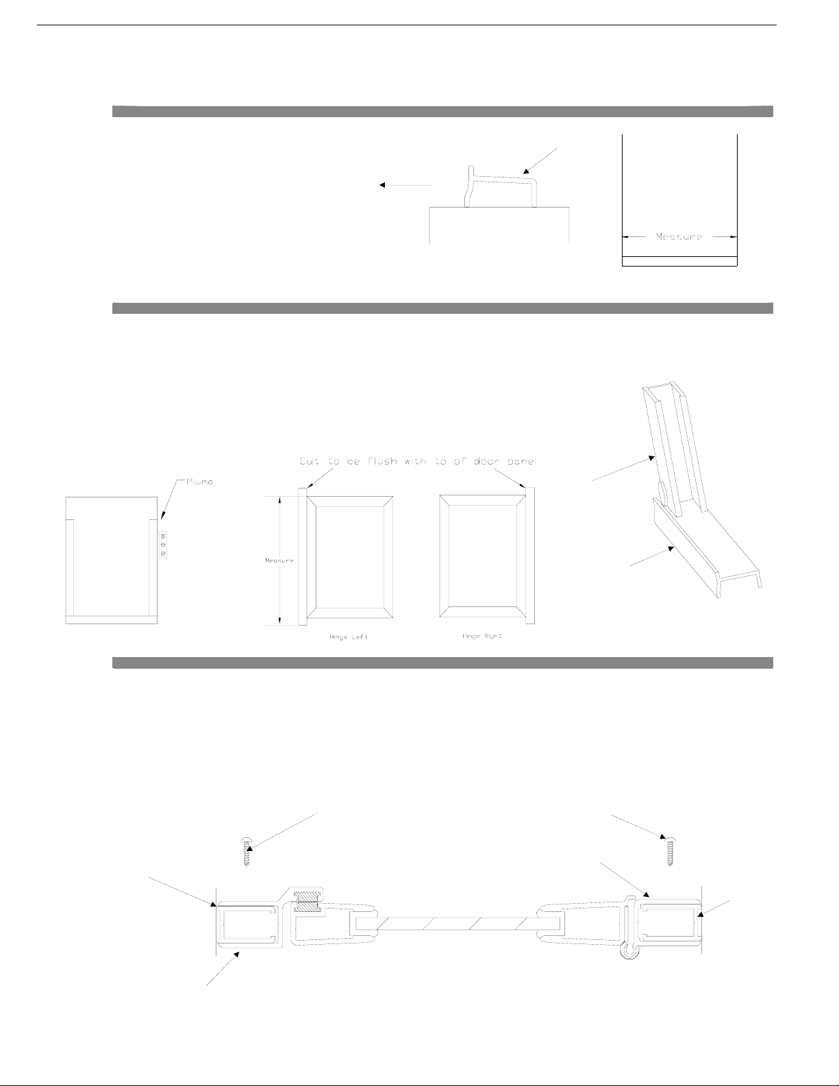
Determine the directions your door will swing and using a hacksaw cut the hinge jamb (A) flush with the top end of
the top rail. Take the 2 wall channels (C) and the latch jamb (B) and cut them to the same length as the full hinge jamb
(A). For a standard height door this measurement would be 66”. Set the wall channels on the dam strip (L). Place a
spacer (a nickel) between the wall channels (C) and the lip of the dam strip (L). This will become important later in
the installation. Use a level to plumb the wall channels (C) and using the factory-predrilled holes as a template, mark
the holes. Remove wall channels and drill the walls using a 3/16” drill bit. (for tile or marble use 3/16” masonry bit).
Insert wall anchors (E) into holes and secure to wall using # 8 X 1 1/2” screws (D).
Set latch jamb (B) in place over the wall channel, but do not secure. From inside the shower, set the hinge jamb (with door attached) in place over the wall
channel. Drill through top pilot hole of the hinge jamb into wall channel using # 32 drill bit. Secure top hole using # 6 X 3/8” screw (F). The door will be
held in place with only the top screw. Plumb hinge jamb and secure the center and bottom holes.
Note: Door is adjustable up to 1” (1/2” at hinge jamb and 1/2” at latch)
Example: A 1000-24 door will fit an opening 24”-25”. For an opening of 24 1/4”, this adjustment will be achieved by taking the hinge and latch jamb
and ad
j
ustin
g
it outward 1/8” each
A
C
C
B
C
L
L
Special Note: The model 1000 and 9000 shower doors are designed to be installed as either a hinge left or a hinge right swing door. Therefore, the wall channels
(C), the hinge jamb (A), and the latch jamb (B) are cut at the factory, approximately 5/8” longer than is necessary. During this installation, you will be instructed
when to cut the above components to achieve a flush look at the top. Doing this will give the door a much more finished look. If you do not desire the flush
appearance at the top, the door can be installed at the factory length. Leaving the material uncut will not hamper the functions of the door.
Note: Only cut metal off if being used as a single swing door
F F
Exterio
r
Inside
Outside

Step4
Step5
Step6
Silicone the entire unit where metal meets wall and curb, we recommend you let silicone set for 24 hours before using shower
Attach the exterior handle (H) and the interior handle (G) to the door with
two # 6 – 32 X 1 1/4” round head screws (K).
H
G
K
J
Next, take the drip bar with tape (I) and the clear drip bar vinyl (L). Slide the
vinyl into the groove at the bottom of the drip bar. Leave 1/4” hanging out at both
ends of the drip bar. Crimp both ends of groove to prevent vinyl from sliding out
of groove. From inside of shower, set drip bar on bottom rail and adjust so
approximately 1/8” daylight space remains between bottom of vinyl and damstrip
(L). Mark with pencil; peel off tape and press drip bar to door on marked
position. You only get one chance.
I
1133 S. McCord Rd. P.O. Box 508
Holland, OH 43528
This manual suits for next models
1
Popular Bathroom Fixture manuals by other brands

Gessi
Gessi RETTANGOLO T 20301 quick start guide

Sanela
Sanela SLZM 18 49180 Mounting instructions

SCHÜTTE
SCHÜTTE 60044 installation instructions

Spectrum Brands
Spectrum Brands Pfister R89-220 Series Maintenance & Care Guide

Uberhaus
Uberhaus 14925004 Operator's manual

RUBINETTERIE
RUBINETTERIE BELLOSTA VIA DELLA SPIGA B3-140/A Installation instruction


