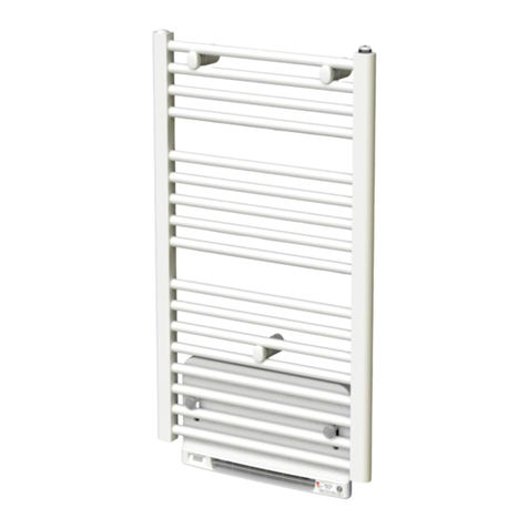
Purmo Amirante E User manual

Notice de moNtage et d’utilisatioN • iNstructioNs for fittiNg aNd use
Sèche-serviettes • Towelwarmer •Badheizkörper • Badkamerradiator• Grzejniki łazienkowe •
Installations- und Gebrauchsanweisung • Installatie en gebruikershandleiding
•Instrukcja instalacji i obsługi •
MANUAL

min 100 mm
min 50 mm
min 50 mm
For Australia: min 600 mm
3
A
5
7 8
4
6
9 10 11
0
12 3
0,6 m 2,4 m
1
0
2
0
12 3
0,6 m 2,4 m
1

Nous vous félicitons pour l’acquisition
de votre nouveau sèche-serviettes RETTIG
Votre appareil est équipé d’un câble d’alimentation avec prise mâle et d’un inter-
rupteur marche/arrêt disposant d’un voyant lumineux rouge allumé lorsque le
sèche-serviettes est sous tension. Il est également possible d’installer l’appareil
de façon permanente/avec câble invisible. Livré avec fixations murales et vis.
Tension d’alimentation : 230 V, 50 Hz
Classe de protection : IP 44
InstallatIon
EmplacEmEnt
Sur un sèche-serviettes fixe et branché en permanence, l'armature peut s'enfon-
cer dans la zone 1. Il faut alors le placer de manière à ce que l'interrupteur
se trouve dans la zone 2 ou la zone 3 (voir les figures 1 à 4). Si vous utilisez la
prise, il faut place le sèche-serviettes tout entier au moins dans la zone 2. Étant
donné que le sèche-serviettes est réversible, l'interrupteur doit se trouver du
côté opposé de la baignoire ou de la douche. Les distances minimales entre le
sèche-serviettes et les surfaces attenantes sont indiquées dans le schéma 5-6.
Il est important de garder à l’esprit que le sèche-serviettes sert à suspendre les
serviettes et non pas à s'agripper.
Veiller à positionner la partie inférieure du sèche-serviettes à au moins 600
mm du sol, de manière qu’elle ne soit pas accessible aux enfants en bas âge. La
distance minimale recommandée par rapport aux surfaces environnantes de
l’appareil est indiquée sur le schéma 3.
montagE Et branchEmEnt élEctrIquE
Pour une parfaite installation des sèche-serviettes, il est primordial que la fixa-
tion du sèche-serviettes soit effectuée de manière appropriée pour l’utilisation
prévue et toute mauvaise utilisation prévisible. Un certain nombre d’éléments
doivent être pris en considération avant de réaliser l’installation comme le type
et la qualité de la fixation entre le sèche-serviettes et le mur, le type et l’état du
mur lui-même ainsi que les charges possibles après le montage.
Il est impératif d'utiliser un dispositif différentiel à courant résiduel de 30 mA si
vous souhaitez installer le sèche-serviettes dans une salle de bains ou une salle
de douche, ou dans une pièce humide.
Le sèche-serviettes doit être fixé sur le mur à l’aide des vis fournies. Les fixations
murales mobiles peuvent s’ajuster en fonction de la surface de votre mur, par
exemple en fonction des joints du carrelage. Elles doivent être ensuite fixées
à l’arrière du sèche-serviettes, avant le montage de celui-ci sur le mur et ce, à
l’aide de la vis centrale de la fixation conformément au schéma 4.
Monter des cache vis sur les fixations murales : tourner le cache vis avec l’en-
coche vers le bas pour le démontage (5A) et appuyer dessus pour l’encliqueter.
Boîte à bornes supérieure et fixation murale, le cas échéant : encliqueter le/les
cache vis fourni(s), schéma 6.
Toutes les fixations murales de l’appareil pouvant pivoter, il est possible de
retourner le sèche-serviettes et de l’installer sur le mur de manière à ce que
l’interrupteur se trouve situé, au choix, en haut, en bas, à gauche ou à droite de
l’appareil.
Conformément à la norme NF C 15 100, un dispositif de coupure omnipolaire
est obligatoire. La distance de séparation des contacts doit être d’au moins
3 mm.
sèchE-sErvIEttEs avEc câblE d’alImEntatIon Et prIsE mâlE
Raccorder la prise du câble d’alimentation à une prise murale.
sèchE-sErvIEttEs avEc câblE d’alImEntatIon sans prIsE mâlE
L’installation devra être effectuée par un électricien agréé.
Retirer la prise du câble d’alimentation et raccorder le câble à un bornier de sor-
tie de câble approprié, en suivant les instructions ci-dessous :
Fil marron = Phase
Fil bleu = Neutre
branchEmEnt du sèchE-sErvIEttEs avEc raccordEmEnt Intégré
(câblE InvIsIblE)
Votre sèche-serviettes peut être installé de façon à ce que le câble d’alimenta-
tion soit invisible. L’installation devra être effectuée par un électricien agréé.
FRANÇAIS
Garantie
La garantie est valable pendant 10 ans, sauf pour les composants électriques,
pour lesquels elle est valable pendant 2 ans. En cas de problèmes ou de
réparations, veuillez contacter votre fournisseur.
MONTAGE À RACCORDEMENT INTÉGRÉ
1. Retirer le cache-bornes de la boîte à bornes en dévissant les vis qui le
maintiennent, voir schéma 7
2. Soulever le connecteur à l’aide d’une pince, voir sché-ma 8.
3. Desserrer les fils du connecteur.
4. Introduire le câble ou équivalent sortant du mur dans le passage prévu à
cet effet, voir schéma 9. Pour le raccordement avec un tube d’installation:
remplacer le passage à membrane par le passage ouvert fourni.
5. Procéder au montage du sèche-serviettes sur le mur.
6. Raccorder les fils entrants au connecteur.
7. Monter en pressant le connecteur sur l’interrupteur, voir schéma 10.
8. Remonter le couvercle du boîtier fourni avec l’appareil et le fixer à l’aide de la
vis, voir schéma 11.
utIlIsatIon
Appuyer sur l’interrupteur pour mettre le sèche-serviettes en service. Le voyant
lumineux s’allume. Le sèche-serviettes peut rester sous tension sans interrup-
tion. La température de l’appareil est toutefois susceptible de varier.
EntrEtIEn
Ne pas utiliser de produits agressifs ou de matières abrasives pour nettoyer ou
essuyer l’appareil.
dIvErs
Le non-respect des instructions de montage pourrait entraîner une surchauffe ou
un mauvais fonctionnement de l’appareil.
Ce modèle de sèche-serviettes est uniquement prévu pour le séchage de linges
lavés à l’eau.
Rettig décline toute responsabilité en cas d’éventuels dommages résultant d’une
mauvaise utilisation du sèche-serviettes.
Si le câble d’alimentation est endommagé, le remplacer par un câble de même
type fourni par Rettig ou un représentant de Rettig.
La température de surface du sèche-serviettes (si celui-ci n’est pas recouvert) ne
peut excéder 60 ºC.
Cet appareil n'est pas prévu pour être utilisé par des personnes (y compris les
enfants) dont les capacités physiques ou mentales sont réduites, ou des per-
sonnes dénuées d'expérience ou de connaissance, sauf si elles ont pu bénéficier,
par l'intermédiaire d'une personne responsable de leur sécurité, d'une sur-
veillance
pu d'instructions préalables concernant l'utilisation de l'appareil. Il convient de
surveiller les enfants pour s'assurer qu'ils ne jouent pas avec l'appareil.

Congratulations on your purchase
of a new towelwarmer from RETTIG
Towel dryer with power supply cable and plug, fitted with 2-pole switch for
connection and disconnection. The switch has a red lamp that lights up when
the towel dryer is switched on. Adaptable for fixed/concealed connection to the
mains. Delivered with wall brackets and screws.
Rated voltage: 230 V 50 Hz . For Australia: 230V-240V
Enclosure class: IP 44
Double insulation
InstallatIon
posItIonIng
On a towelwarmer, which is fixed and permanently connected, the frame may
protrude into zone 1, but then it must be positioned so that the switch is locat-
ed in zones 2 or 3, see figures 1-4. If the plug is used, the whole of the towel
warmer must be positioned in at least zone 2. Since the towel dryer is revers-
ible, the switch should be positioned facing away from the bath or shower. The
recommended minimum dimensions to limiting surfaces in the vicinity are indi-
cated in figures 5-6. It is important to remember that the towel dryer is there to
hang towels on and must not be used to hold on to.
To avoid injuries to small children the towelwarmer must be positioned so that
the lowest part is at least 600 mm above the floor. The recommended minimum
dimensions to other limiting surfaces in the vicinity are indicated in figure 3.
Wall-mountIng and connEctIon
For the correct installation of towelwarmers it is essential that the fixing of the
towelwarmer is carried out in such a way that it is suitable for intended use
and predictable misuse. A number of elements need to be taken into considera-
tion including the fixing method used to secure the towelwarmer to the wall,
the type and condition of the wall itself, and any additional potential forces or
weights, prior to finalising installation.
A residual current device of 30 mA is compulsory if the towel warmer is installed
in a bathroom, shower or other wet areas.
The towelwarmer is mounted on a wall with the enclosed screws. The wall
brackets can be moved to suit any tile joints etc. They can be loosened and tight-
ened from the back with the screw in the centre of the wall bracket before the
towelwarmer is mounted on the wall, see figure 4.
The cover rings are fitted to conceal the wall screws: the cover rings for the feet
are turned in position with the recess for dismantling facing downwards (5A)
and then snapped into place, see figure 5.
The enclosed cover ring(s) is/are snapped over the connection housing and
where appropriate the wall bracket, see figure 6.
All the feet and wall brackets can be turned round so that the towel dryer can
be reversed.
The towelwarmer can then be mounted with the wall bracket and switch either
at the top or bottom, on the left or right side.
toWElWarmEr WIth poWEr supply cablE and plug
The towelwarmer’s power supply cable with the plug is connected to a wall
socket.
This appliance is equipped with an all-pole switch with a contact separation of
3 mm.
toWElWarmEr WIth poWEr supply cablE WIthout plug
The electrical installation must be done by an authorised electrician.
Remove the plug from the power supply cable and connect the 2-wire cable to a
suitable junction box as follows:
Brown wire = phase
Blue wire = neutral
toWElWarmEr WIth concEalEd connEctIon
The towelwarmer can as an alternative be fitted with a concealed electrical con-
nection. The electrical installation must be done by an authorised electrician.
INSTALLATION WITH CONCEALED CONNECTION
1. Remove the cover on the connection housing by undoing the screws holding
the cover in place, figure 7.
2. Lift up the connector by means of a pair of pliers, figure 8.
3. Unscrew the wires from the connector.
4. Insert the cable or the equivalent from the wall through the inlet, figure 9.
For connection with wiring tube: replace the fitted membrane inlet with the
enclosed open inlet.
5. Mount the towelwarmer on the wall.
6. Connect the incoming wires to the connector.
7. Press the connector on the switch, figure 10.
8. Fit and screw tight the enclosed sealed cover, figure 11.
usIng thE toWElWarmEr
The towelwarmer is switched on by pressing the switch. The lamp on the switch
lights up when the towel dryer is switched on. The towelwarmer can be left
switched on permanently without problem. The temperature of the towelwarm-
er can vary.
product carE
Only mild detergent should be used to clean and wipe the towelwarmer.
mIscEllanEous
Failure to follow the installation instructions can lead to overheating and mal-
functioning.
This towelwarmer is only intended for the drying of textiles washed in water.
The appliance is not intended for use by young or infirm persons without super-
vision. Young children should be supervised to ensure that they do not play with
the appliance.
Rettig cannot accept responsibility for any damage resulting from incorrect use.
If the power supply cable is damaged it must be replaced by the same type sup-
plied by Rettig, or Rettig’s representative.
The maximum surface temperature that can be achieved on a free surface is
60ºC.
This appliance is not intended for use by persons (including children) with
reduced physical, sensory or mental capabilities, or lack of experience and
knowledge, unless they have been given supervision or instruction concerning
use of the appliance by a person responsible for their safety. Children should be
supervised to ensure that they do not play with the appliance.
Waranty
The warranty is valid for 10 years except for electrical components which
is valid for 2 years. In the event of any problems or repairs, please contact
your supplier.

Herzlichen Glückwunsch zum Kauf Ihres
Handtuchtrockners von RETTIG!
Handtuchtrockner mit Anschlusskabel und Netzstecker sowie Schalter zum
Ein- und Ausschalten. Der Schalter hat eine rote Anzeigelampe, die bei
Einschalten des Handtuchtrockners leuchtet. Anpassbar für festen/verdeckten
Stromanschluss. Wandhalterungen und Schrauben sind im Lieferumfang ent-
halten.
Nennspannung: 230 V 50 Hz
Schutzklasse: IP 44
Doppelte Isolierung
InstallatIon
platzIErung
Der Rahmen eines Handtuchtrockners, der fest und dauerhaft montiert ist, darf
in Zone 1 ragen, dann muss er jedoch so positioniert werden, dass der Schalter
sich, wie in Abbildung 1-4 gezeigt, in Zone 2 oder 3 befindet. Wenn der Stecker
verwendet wird, muss der gesamte Handtuchtrockner mindestens in Zone 2
angebracht werden.Der Handtuchtrockner ist umkehrbar. Montieren Sie ihn
so, dass der Schalter von der Badewanne oder der Dusche weg weist. Die emp-
fohlenen Mindestabstände zu angrenzenden Flächen sind in Abbildung 5 und
6 angegeben. Bitte beachten: der Handtuchtrockner ist zum Aufhängen von
Handtüchern konzipiert und nicht, um sich daran festzuhalten oder zu hängen.
Um Verletzungen von Kleinkindern zu verhüten, ist der Handtuchtrockner min-
destens 600 mm über dem Fußboden anzubringen. Die empfohlenen Abstände
zu den sonstigen Begrenzungsflächen gehen aus Abb. 3 hervor.
montagE und anschluss
Bei der Montage von Handtuchtrockners ist zu beachten, dass die Befestigung
von der Handtuchtrocknern so dimensioniert wird, dass sie für die bestim-
mungsgemäße Verwendung und vorhersehbarer Fehlanwendung geeignet ist.
Hierbei sind insbesondere die Verbindung mit dem Baukörper sowie dessen
Beschaffenheit, die Geeignetheit des Montagezubehöres und die möglichen
Belastungen nach erfolgter Montage zu prüfen.
Bei der Montage in Badezimmer, Dusche oder anderen Nassbereichen muss ein
Fehlerstromschutzschalter mit einer Kapazität von maximal 30mA eingebaut
werden.
Der Handtuchtrockner wird an der Wand mittels mitgelieferter Schraube befes-
tigt. Die Wandhalter sind verschiebbar, um die Bohrlöcher den Fliesenfugen od.
Ähnl. anzupassen. Sie werden mittels Zentrumschraube am Halter von hinten
gelöst und wieder gesichert, bevor der Handtuchtrockner an der Wand montiert
wird (siehe Abb. 4).
Die Abdeckringe werden angebracht, um die Wandschrauben zu verkleiden. Die
Füße der Abdeckringe werden in ihre Position gedreht – wobei die Aussparung
für die Demontage (5A) nach unten zeigt – und dann eingerastet (siehe Abb. 5).
Die mitgelieferten Abdeckringe werden über dem Anschlussgehäuse und evt.
der Wandhalterung eingerastet (siehe Abb. 6).
Sämtliche Wandhalter und Füße des Handtuchtrockners können geschwenkt
werden, so dass sich der Handtuchtrockner wenden lässt.
Wandhalterung und Handtuchtrockner können daher montiert werden, indem
der Schalter oben, unten, rechts oder links angebracht wird.
Dieses Gerät besitzt einen allpoligen Schalter mit einem Kontaktabstand von 3
mm.
handtuchtrocknEr mIt anschlusskabEl und nEtzstEckEr
Der Stecker des Anschlusskabels des Handtuchtrockners wird an die
Wandsteckdose angeschlossen.
handtuchtrocknEr mIt anschlusskabEl ohnE nEtzstEckEr
Der Stromanschluss ist von einem zuständigen Elektriker auszuführen.
Entfernen Sie den Netzstecker des Anschlusskabels und schließen Sie das zwei-
adrige Kabel an eine geeignete Installationsdose mit folgender Polung an:
Braune Ader = Phase
Blaue Ader = Nullleiter
Garantie
Die Garantie hat eine Gültigkeitsdauer von 10 Jahren, mit Ausnahme der
elektrischen Komponenten, deren Garantiedauer 2 Jahre beträgt. Sollten
sich Probleme oder Reparaturbedarf ergeben, wenden Sie sich bitte an Ihren
Händler.
handtuchtrocknEr mIt vErdEcktEm stromanschluss
Der Handtuchtrockner kann auch mit verdecktem Stromanschluss montiert wer-
den. Der Stromanschluss ist von einem zuständigen Elektriker auszuführen.
MONTAGE MIT VERDECKTEM STROMANSCHLUSS
1. Schrauben des Deckels der Anschlussdose lösen und Deckel entfernen
(siehe Abb. 7).
2. Kontakt mittels Zange anheben (Abb. 8).
3. Adern vom Kontakt abschrauben.
4. Die aus der Wand kommende Leitung durch die Durchführung stecken
(Abb. 9). Bei Anschluss mit Installationrohr: vorhandene Membranen-
durchführung durch mitgelieferte offene Durchführung ersetzen.
5. Handtuchtrockner an Wand montieren.
6. Ankommende Leitung an Kontakt anschließen.
7. Kontakt fest am Schalter andrücken (Abb. 10).
8. Den mitgelieferten, abgedichteten Deckel montieren und festschrauben
(Abb. 11).
bEtrIEb
Der Handtuchtrockner wird durch Betätigen des Schalters eingeschaltet. Wenn
sich der Handtuchtrockner in Betrieb befindet, leuchtet die Schalterdiode. Ein
Dauerbetrieb des Handtuchtrockners ist problemlos möglich. Die Temperatur des
Handtuchtrockners kann variieren.
pflEgE
Für Reinigung und Pflege des Handtuchtrockners nur schonende
Reinigungsmittel verwenden!
sonstIgEs
Wenn die Montageanleitung nicht befolgt wird, kann dies zur Überhitzung und
zum Funktionsausfall des Handtuchtrockners führen.
Der Handtuchtrockner ist nur für das Trocknen von Textilien vorgesehen, die von
Wasser befeuchtet wurden.
Rettig haftet nicht für Schäden, die auf falsche Montage oder Bedienung zurück-
zuführen sind.
Bei Schäden am Anschlusskabel ist dieses durch ein Kabel des gleichen Typs zu
ersetzen (wird von Rettig oder vom Vertragshändler geliefert).
Die maximale Oberflächentemperatur des Handtuchtrockners beträgt 60ºC.
Das Gerät darf von Kindern bzw. von behinderten oder technisch unerfahrenen
Personen nur dann gehandhabt werden, wenn sie im Gebrauch des Geräts
unterrichtet worden sind. Es ist dafür zu sorgen, dass Kinder nicht am Gerät
herumspielen.
This manual suits for next models
1
Table of contents
Languages:
Other Purmo Bathroom Fixture manuals
Popular Bathroom Fixture manuals by other brands

Kohler
Kohler Mira Sport Max J03G Installation and user guide

Moen
Moen 186117 Series installation guide

Hans Grohe
Hans Grohe Raindance Showerpipe 27235000 Instructions for use/assembly instructions

Signature Hardware
Signature Hardware ROUND SWIVEL BODY SPRAY 948942 Install

fine fixtures
fine fixtures AC3TH installation manual

LIXIL
LIXIL HP50 Series quick start guide