9
DWichtige Hinweise
Die Einbaulage ist beliebig. Der Spannungsausgang ist kurzschlussfest, ein Anlegen einer Überspannung am Spannungsausgang zerstört das Gerät.
Die Druckbereiche (Messbereiche) sind auf dem Geräteetikett angeben. Bei Messdrücken außerhalb dieses Bereiches kommt es zu Fehlmessungen,
zu erhöhten Abweichungen oder es kann zur Zerstörung des Druckmessumformer führen.
– Achtung, beim Einführen der Kabel ist darauf zu achten, dass dieses nicht unterhalb der Platine geführt wird.
Hierdurch können die Schlauchverbindungen geknickt oder beschädigt werden!
– Die Druckeingänge sind „gepolt“, d.h. die Überdruckleitung muss am Eingang P+, die Unterdruckleitung am Eingang P– angeschlossen werden.
– Am Einstellregler kann das Ausgangssignal um ±10 % vom Endwert des Messbereiches verschoben werden.
Somit kann man eventuelle Alterungs- und Drifterscheinungen kompensieren.
– Beim Betrieb des Gerätes außerhalb des Spezifikationsbereiches entfallen alle Garantieansprüche.
Als AGB gelten ausschließlich unsere sowie die gültigen „Allgemeinen Lieferbedingungen für Erzeugnisse und Leistungen der Elektroindustrie“
(ZVEI Bedingungen) zuzüglich der Ergänzungsklausel „Erweiterter Eigentumsvorbehalt“.
Außerdem sind folgende Punkte zu beachten:
– Vor der Installation und Inbetriebnahme ist diese Anleitung zu lesen und die alle darin gemachten Hinweise sind zu beachten!
– Bei Montage im Außenbereich ist ein geeigneter Wetter- und Sonnenschutz zu verwenden.
– Der Anschluss der Geräte darf nur an Sicherheitskleinspannung und im spannungslosen Zustand erfolgen. Um Schäden und Fehler am Gerät (z.B. durch
Spannungsinduktion) zu verhindern, sind abgeschirmte Leitungen zu verwenden, eine Parallelverlegung zu stromführenden Leitungen zu vermeiden und die
EMV- Richtlinien zu beachten.
– Dieses Gerät ist nur für den angegebenen Verwendungszweck zu nutzen, dabei sind die entsprechenden Sicherheitsvorschriften des VDE, der Länder, ihrer
Überwachungsorgane, des TÜV und der örtlichen EVU zu beachten. Der Käufer hat die Einhaltung der Bau- und Sicherungsbestimmung zu gewährleisten
und Gefährdungen aller Art zu vermeiden.
–
Für Mängel und Schäden, die durch unsachgemäße Verwendung dieses Gerätes entstehen, werden keinerlei Gewährleistungen und Haftungen übernommen.
– Folgeschäden, welche durch Fehler an diesem Gerät entstehen, sind von der Gewährleistung und Haftung ausgeschlossen.
– Montage und Inbetriebnahme der Geräte darf nur durch Fachpersonal erfolgen.
–
Es gelten ausschließlich die technischen Daten und Anschlussbedingungen der zum Gerät gelieferten Montage- und Bedienungsanleitung, Abweichungen zur
Katalogdarstellung sind nicht zusätzlich aufgeführt und im Sinne des technischen Fortschritts und der stetigen Verbesserung unserer Produkte möglich
.
– Bei Veränderungen der Geräte durch den Anwender entfallen alle Gewährleistungsansprüche.
– Dieses Gerät darf nicht in der Nähe von Wärmequellen (z.B. Heizkörpern) oder deren Wärmestrom eingesetzt werden, eine direkte Sonneneinstrahlung
oder Wärmeeinstrahlung durch ähnliche Quellen (starke Leuchte, Halogenstrahler) ist unbedingt zu vermeiden.
– Der Betrieb in der Nähe von Geräten, welche nicht den EMV- Richtlinien entsprechen, kann zur Beeinflussung der Funktionsweise führen.
– Dieses Gerät darf nicht für Überwachungszwecke, welche dem Schutz von Personen gegen Gefährdung oder Verletzung dienen und
nicht als Not-Aus-Schalter an Anlagen und Maschinen oder vergleichbare sicherheitsrelevante Aufgaben verwendet werden.
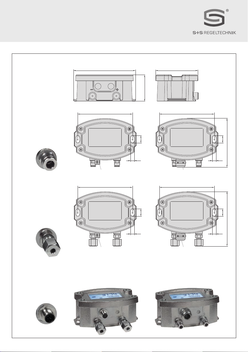
– Die Gehäuse- und Gehäusezubehörmaße können geringe Toleranzen zu den Angaben dieser Anleitung aufweisen.
– Veränderungen dieser Unterlagen sind nicht gestattet.
– Reklamationen werden nur vollständig in Originalverpackung angenommen.
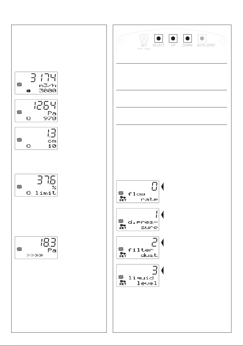
Hinweise zur Inbetriebnahme:
Dieses Gerät wurde unter genormten Bedingungen kalibriert, abgeglichen und geprüft. Bei Betrieb unter abweichenden Bedingungen empfehlen wir Vorort eine
manuelle Justage erstmals bei Inbetriebnahme sowie anschließend in regelmäßigen Abständen vorzunehmen.
Eine Inbetriebnahme ist zwingend durchzuführen und darf nur von Fachpersonal vorgenommen werden!
Vor der Montage und Inbetriebnahme ist diese Anleitung zu lesen und die alle darin gemachten Hinweise sind zu beachten!
DWichtige Hinweise
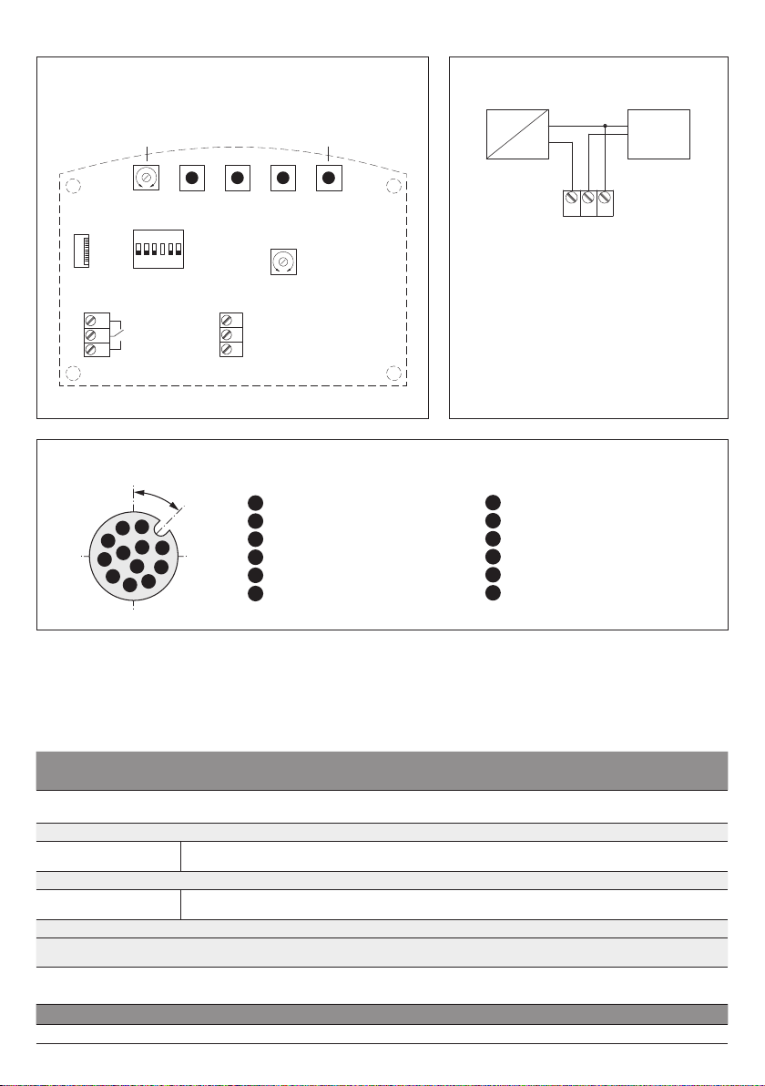
Schaltbild
Parallelbetrieb
Schaltbild
Einzelbetrieb
VERSORGUNGSSPANNUNG:
Als Verpolungsschutz der Betriebsspannung ist bei dieser Gerätevariante
eine Einweggleichrichtung bzw. Verpolungschutzdiode integriert. Diese
interne Einweggleichrichtung erlaubt auch den Betrieb mit AC-Versorgungs-
spannung bei 0 -10 V Geräten.
Das Ausgangssignal ist mit einem Messgerät abzugreifen. Hierbei wird
die Ausgangsspannung gegen das Nullpotenial (O V) der Eingangsspannung
gemessen!
Wird dieses Gerät mit
DC - Versorgungsspannung
betrieben, ist der Be-
triebsspannungseingang UB+ für 15...36 V DC - Einspeisung und UB– bzw.
GND als Masseleitung zu verwenden!
Werden mehrere Geräte von einer 24 V
AC - Spannung
versorgt, ist
darauf zu achten, dass alle „positiven“ Betriebsspannungseingänge (+) der
Feldgeräte miteinander verbunden sind, sowie alle „negativen“ Betriebs-
spannungseingänge (–) = Bezugspotential miteinander verbunden sind
(phasengleicher Anschluss der Feldgeräte). Alle Feldgeräteausgänge
müssen auf das gleiche Potential bezogen werden!
Bei Verpolung der Versorgungsspannung an einem der Feldgeräte würde
über dieses ein Kurzschluss der Versorgungsspannung erzeugt. Der somit
über dieses Feldgerät fließende Kurzschlussstrom kann zur Beschädigung
dieses Gerätes führen.
Achten Sie daher auf die korrekte Verdrahtung!
Schaltung Schaltung
0-10V
0V/GND
0-10V
0V/GND
Versorgung mit
AC 24V~ 0V
DC 15-36V = GND
AC 24V~ 0V
DC 15-36V = GND
Schaltung
0-10V
0V/GND
V
Versorgung mit