SPM intellinova compact INS06 Ex Owner's manual

Installation and Operation Instructions
INS06 Ex

blanc
SPM Instrument AB • Box 504 • SE-645 25 Strängnäs • Sweden Technical data subject to change without notice.
ISO 9001 certified. ©Copyright SPM 2022-11. 72086 B Rev.8
Additional information
71421 “Installation of Measuring Equipment” describes the installation of transducer lines
(transducers, matching units, cables etc). “
72260 “Condmaster®Ruby, Installation and system administration” describes how to install the
Condmaster Entity Server (CES) Service, Condmaster software installation and setup, etc.
72261 “Condmaster®Ruby User guide” describes how to set up measuring assignments, work with
the alarm list, evaluation functions, reports, etc.
72262 “CES Admin Portal User guide” describes license activation, management of databases,
users, user groups, system settings, etc.
Trademarks
Airius, CondID, Condmaster, DuoTech, EVAM, HD ENV, Intellinova, Leonova, Leonova Diamond, Leonova
Emerald, SPM and SPM HD are trademarks of SPM Instrument AB.
All other trademarks are the property of their respective owners.
Patents
www.spminstrument.com/patents
© Copyright SPM Instrument AB. ISO 9001 certified.

Contents
Installation Instructions
Safety Arrangements........................................ 2
Installation Precautions..................................... 3
System Description........................................... 4
Conformity with Standards............................... 4
Mechanical Installation ..................................... 5
System Unit – Overview.................................... 6
Electrical Installation......................................... 7
Cable Entries ................................................. 7
Selection of Cables........................................ 7
Power Supply................................................. 8
Intrinsic Safety Earth ...................................... 9
Network Connection...................................... 9
Connection to PC .......................................... 9
Bearing Monitoring ........................................ 11
Connection of Shock Pulse Transducers....... 11
Mounting TNC Connector 93022 ................ 12
Vibration Monitoring ..................................... 13
Connection of Vibration Transducers ........... 13
Connection to IS-earth................................. 13
Connection of Digital Inputs, DI/RPM............ 14
Connection of Analog Inputs, AI .................... 15
Connection of Digital Outputs, DO................ 16
SD Memory Card ............................................ 17
Configuration ................................................. 17
Wi-Fi Ethernet unit (Option) ........................... 18
Service and Maintenance................................ 19
Technical Specifications INS06 Ex .................. 20
Part Numbers ................................................. 21
Approved Spares and Accessories ................. 21

– 2 –
Safety Arrangements
Safety Arrangements
General
All persons performing installation or service on rotating
machines and electrical equipment should be authorised
and familiar with general safety rules and IEC symbols
as well as local requirements, rules and regulations. This
equipment must only be installed, used and maintained
by competent personnel. Such personnel shall have
undergone training, which included instruction on the
various types of protection and installation practices, the
relevant rules and regulations, and on the general princi-
ples of area classification. Appropriate refresher training
shall be given on a regular basis (See EN 60079-17).
The installation, use and maintenance of this equipment
must comply with the appropriate European, national and
local regulations, which may include reference to the IEC
standards IEC60079-14, IEC60079-17 and IEC60079-19.
In addition, particular industries or end users may have
specific requirements relating to the safety (or health)
and these requirements should also be met. Instructions
and specifications issued by the manufacturer must be
followed.
In case of doubt, the local management should be con-
sulted. SPM Instrument will not be responsible for any
accident caused by persons not observing these Safety
Precautions.
The explosion-proof Intellinova®Compact Ex units are
used for stationary installation in hazardous areas classi-
fied to EN 60079-10 as Zone 2 or Zone 22.
Do not leave this manual or any other object inside the
enclosure when the unit is in service.
Operate the explosion-proof Intellinova®Compact Ex
units only for their intended purpose when in an undam-
aged and clean condition, and only where the material of
the enclosure is compatible with the environment.
If assembly is not carried out correctly, it cannot be ensured
that the cabinet is a restricted breathing enclosure EPL “Ex
nR” and dust ignition protection by enclosure EPL “Ex tc”.
No modifications that are not expressly specified in this
Manual are allowed to the Intellinova®Compact Ex units.
Whenever work is done on the Intellinova®Compact Ex
units, the national safety and accident prevention regula-
tions and the safety instructions given in this Manual must
always be observed!
Disconnection
Before starting installation work on machines, make sure
that main power is off and will stay off until the work is
done. Do not simply pull the switch - remove the fuses,
lock the fuse box, put up warning signs. Check all termi-
nals to ensure that the equipment is voltage-free by using
a Ex-certified voltage tester.
Electrical Installation
Always read the instructions delivered with the equip-
ment before performing installation or service on elec-
tric equipment. If you are in doubt, please contact your
local SPM Instrument representative before installing
the equipment. Damage of the equipment caused by
incorrect installation is not covered by product warranty.
Before starting installation work, make sure that the
main power switch is in off position and will stay off until
the work is done. Check that all terminals, marked with
protective earth IEC symbol, are properly connected to
the protective earthing conductor of the building instal-
lation wiring. In some countries, the term "protective
grounding" is used instead of "protective earthing".
Earth and ground are used synonymously in this instal-
lation instruction. Choose installation tools that are safe
and suitable for its working environment. Electrical risks
can sometimes be eliminated by using air, hydraulic or
handpowered tools. These are especially useful in harsh
conditions.
System Components
To ensure optimum safety for user and environment,
only original system components available from SPM
Instrument should be used. When using non-original
components, the compliance with EU directive with re-
spect to electric safety, EMC, ATEX and machine safety
is not guaranteed by SPM Instrument.
Reapplying Power
For human safety, ensure that the electrical equipment
or installation is electrically safe. Before starting the
machine, make sure that all protection covers on the
machine are mounted and secured. Perform periodic
pressure testing to ensure enclosure is not leaking.
Symbols
Protective
earth
ATEX and UKEX certified
electrical equipment for
explosive atmospheres.
EU certified
equipment
Rotating
parts
Risk for electric
shock
Caution
Intrinsic safety
earth

– 3 –
Installation Precautions
For installation and operation, the rules of generally
accepted engineering practice, the provisions of EN
60079-14: 'Electrical installations design, selection and
erection', EN 60079-17: 'Electrical installations inspec-
tion and maintenance' and the instructions set out in
this Manual must be observed.
Installation of Measuring Units and Measuring Terminals
The explosion-proof Intellinova®Compact Ex units must
be installed at carefully selected locations where they
cannot be damaged by mobile equipment such as pallet
and forklift trucks.
Measuring units and terminals should be located in a
protected position assigned by the local management.
The units shall be easily accessible for undisturbed
measurements and service. The measuring equipment
should be intended and specified for use in existing
environment. It is important that you read the operating
instructions completely and follow all safety precau-
tions before operating the measuring units. Electrical
connections and wiring should be performed only by
suitably trained personnel.
Specific Condition of Use
The following conditions relate to safe installation and/
or use of the equipment:
• A warning label must be shown, stating “WARNING
– Do not open, maintain or service in an area where
explosive atmosphere may be present”
• A warning label must be shown, stating “WARNING –
Ensure door is correctly tightened when closed”
Work Regulations
All personnel should be provided with the local work
regulation before any work is commenced. It is impor-
tant that parts of metal, rubber and plastics are dumped
in special containers. Such parts can cause bad accidents
and production disturbances if dropped on the wrong
place. From an environmental point of view, wrapping
materials should be collected so as not to cause dam-
age. Precautions should also be taken when drilling,
tapering and grinding to avoid chips and grindings
causing accidents and production disturbances.
Inspection and Acceptance
Inspection of transducer positioning, connections, ca-
ble laying, TMU installations and strapping should take
place after finished installation.
After completed installation, the restricted breathing
properties should be checked according to “Periodic
pressure testing”.
The installation should be inspected and accepted when
in compliance with EN60079-14.
Installation Precautions
Installation in Hazardous environments
The Intellinova®Compact Ex unit meets the requirement
to be installed in safe or Ex zone 2/22. Sensors installed
in Ex zone 0/20 and 1/21 is connected to the Intellinova®
Compact Ex unit with Ex interfaces. A typical hazardous
installation is exemplified as illustration below.
Read the entire instruction manual
before the products are put into use!
– 4 –
System Description
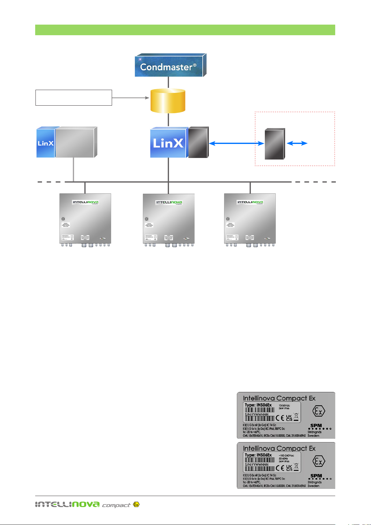
System Description
The Intellinova®Compact Ex system is a permanently
installed, online machine condition monitoring sys-
tem. It is handled by the comprehensive software
Condmaster®Ruby or Condmaster®Nova, which controls
the system, collects, stores, and evaluates the measuring
results. Via Ethernet, the Intellinova system is connected
to a computer with the software Condmaster®, and the
communication program LinX. The measuring assign-
ments are set up in Condmaster®and LinX transmits the
measuring assignments to and reads the result file from
the Intellinova System Unit. Measuring results are stored
in a historical database. System functionality and trans-
ducer lines are automatically monitored for malfunctions.
The core of the system is the SPM Instrument software,
Condmaster®, which receives the measuring results from
all SPM Instrument devices for evaluation and presenta-
tion. Based on extensive empirical data, international
standards and machine statistics, the evaluation result is
an easy-to-understand color code, highlighting potential
trouble spots. By calibrating and adjusting limit values,
the automatic evaluation process can be tuned with great
precision to get an immediate, reliable diagnosis. Intel-
linova implements OPC™ Data Access, through which
process control data can be transferred seamlessly to and
from any data source, such as DCS or SCADA systems,
PLCs, databases, gauges, spreadsheets etc. to any OPC
compliant application. Intellinova®Compact Ex is robustly
designed in every aspect, made for harsh and potentially
explosive environments and long-term use.
Conformity with Standards
The explosion-proof Intellinova®Compact Ex units meet
the requirements of EN 60079-0, EN 60079-15 and EN
60079-31. They have been developed, manufactured
and tested in accordance with ISO 9001 and EN ISO/
IEC 80079-34.
Existing SPM online systems
System Unit 1
Data base
Service laptop
Process
Control
System
Ethernet
Data Access
Customer systems
Ethernet/
SD card
System Unit 2 System Unit 3
OPC
Client/
Server
FSS
Field Support
Software
OPC
Client/
Server

– 5 –
Installation with mounting braces (SPM 81524)
Mechanical Installation
Mechanical Installation
Mounting
The Intellinova®Compact Ex units have an industrial cabi-
net designed for wall mounting. It should be mounted
vertically with 4 bolts through the 8 mm holes in mount-
ing braces as shown in the figure. Use mounting bolts
with material quality Stainless Steel recommended to
DIN912, ISO4762.
The Intellinova®Compact Ex unit shall be mounted in a
way that allows access to the test port.
Environment
The cabinet is made of stainless steel and has silicone
gaskets (IP66). Environmental limitations are according
to the technical specification. The electrical environment
must be suitable for data cables.
380
380
210
410
434
326
10
340
344
XX
– 6 –
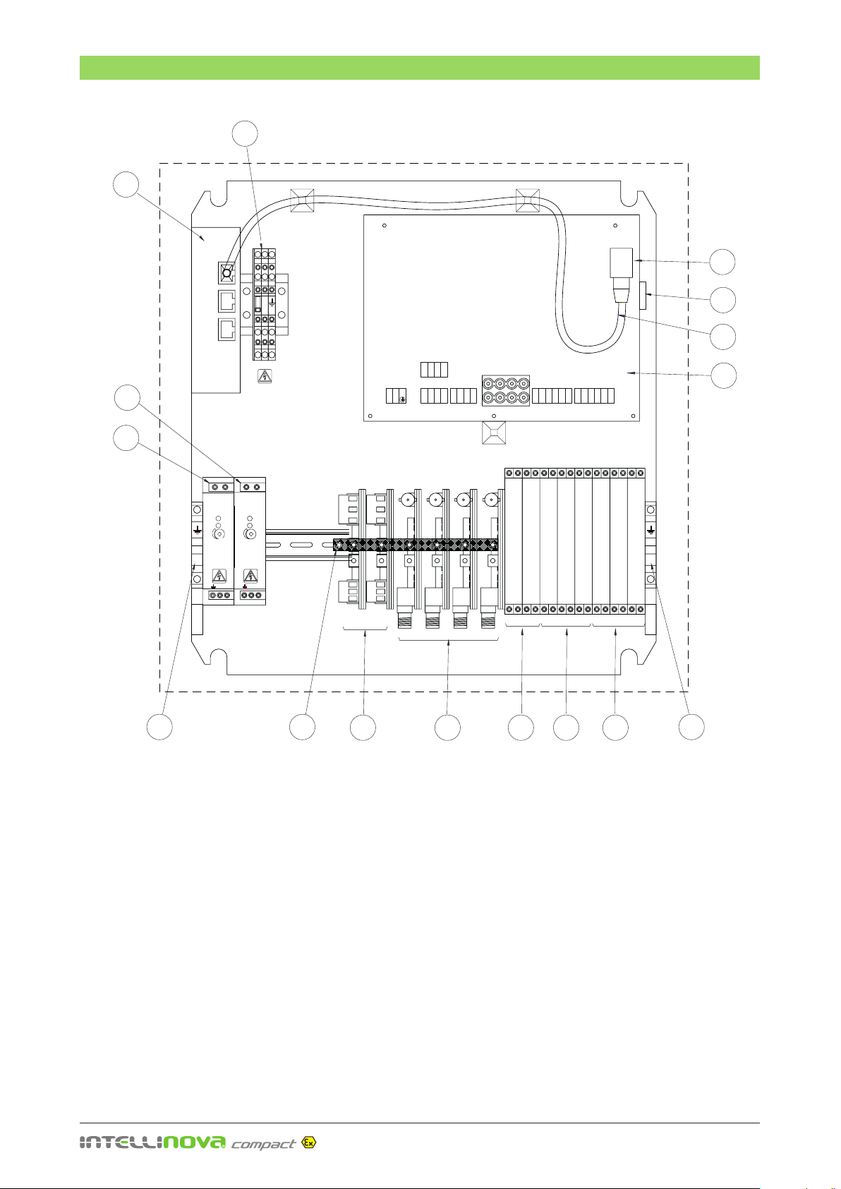
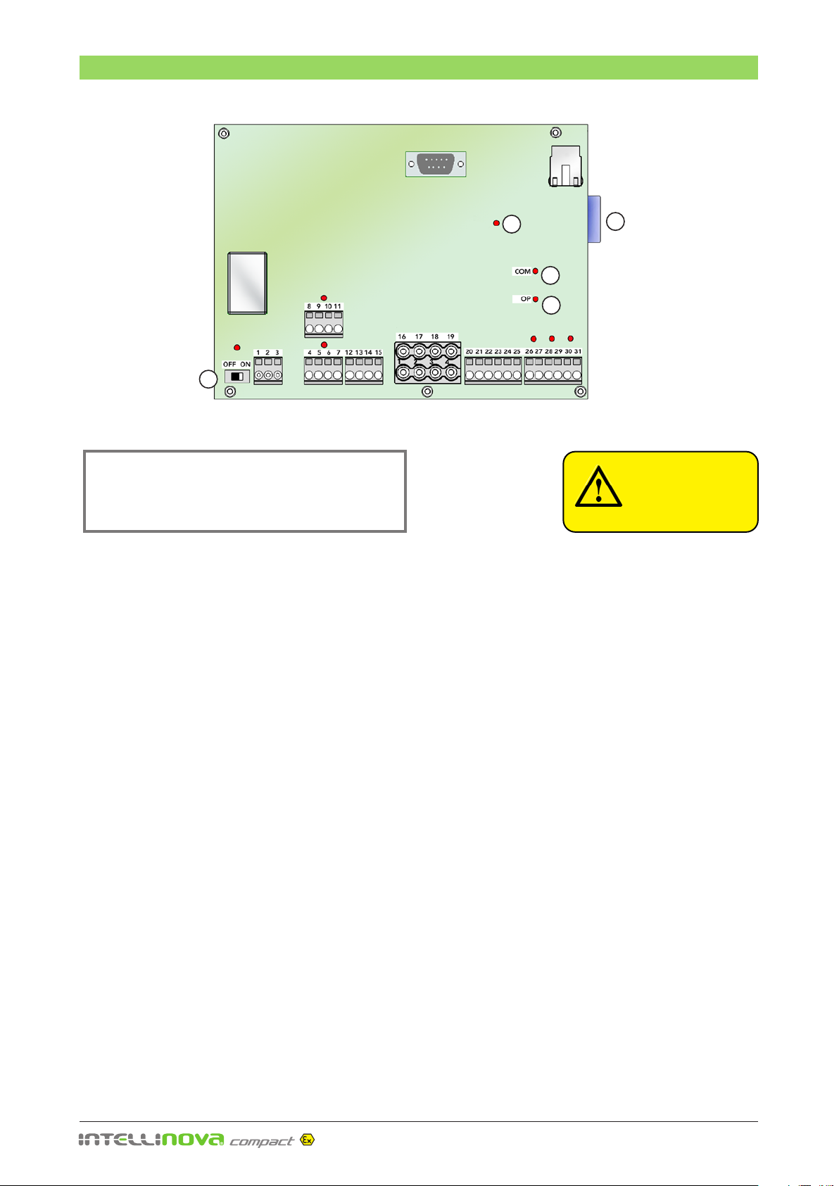
System Unit – Overview
IS-EARTH
IS-EARTH
14
2
10987
13
4
6
5
1
3
11 12
12
15
+ -
+ -
V- V+
V- V+
24 VDC/0.75A
24 VDC/0.75A
LO
LO
ON
ON
Vout ADJ.
Vout ADJ.
100-240 VAC
100-240 VAC
0.5A
0.5A
47-63Hz
47-63Hz
N
N
L
L
1
1
2
2
3
3
4
4
5
5
6
6
7
7
12
12
13
13
14
14
15
15
20
20
21
21
22
22
23
23
24
24
25
25
26
26
27
27
28
28
29
29
30
30
31
31
8
8
9
9
10
10
11
11
16
16
17
17
18
18
19
19
V- V+
V- V+
12 VDC/0.75A
12 VDC/0.75A
LO
LO
ON
ON
Vout ADJ.
Vout ADJ.
100-240 VAC
100-240 VAC
0.5A
0.5A
47-63Hz
47-63Hz
N
N
L
L
N
N
L1
L1
1 Circuit board
2 Ethernet connector
3 SD memory card
4 Power supply terminal blocks
5 Power supply unit 12V DC
6 Power supply unit 24V DC, Option
7 VIB transducer Ex interface
8 SPM transducer Ex interface
9 RPM/DI sensor Ex interface
10 Analog in (AI) Ex interface. Special order only.
11 Digital out (DO) Ex interface. Special order only.
12 IS-earth terminal blocks
13. Earth rail
14 Ethernet switch, Option
15. Internal Ethernet cable, Option
System Unit – Overview

– 7 –
Electrical Installation
Test Port
A
A
B
B
C
C
D
D
E
E
E
E
F
F
G
G
BOTTOM VIEW
PE Earth screw
Cable Entries
For type “Ex nR” and “Ex tc” explosion-proof Intellinova®
System units, only those cable and conductor entries and
plugs that possess an EC type-examination certificate
(Category 3 G or 3 D) issued by a European Notified Body
as per European Standards EN 60079-0, EN 60079-7, EN
60079-15 and EN 60079-31 may be used.
The cable and conductor glands must be installed to
prevent self-loosening and to ensure permanent sealing
of the cable and conductor entry points.
The spacing between the cable glands is such that a
torque wrench can be used to secure the gland bodies
in the enclosure wall and to tighten the seals around the
cables.
Intrinsically safe circuits must enter and leave the enclo-
sure via separate cable glands that are specially marked
with a light blue color.
If any cable and conductor glands are not used or are no
longer needed, the holes and redundant gland bodies
must be blanked off with suitable blind plugs or caps.
The cabinet has the following cable glands:
A. One cable gland M20 x1.5 for power supply cable,
cable diameter 6 to 12 mm.
B. Three cable glands M16 x1.5 for digital in DI/RPM
cables, cable diameter 4.5 to 10 mm.
C. Two cable glands of type M25 x1.6 for up to four
measuring cables each with diameter 4.5 to 6 mm.
D. One cable gland of type M16x1.5 for a standard
Ethernet cable with cable diameter 4.5 to 10 mm.
E. Two cable glands of type M16 x1.5 for Intrinsic
Safety Earth, cable diameter 4.5 to 10 mm.
Tighten torque
Cable gland
size
Connection thread
(Nm)
Pressing nut
(Nm)
M16x1.5 2.5 3.75
M20x1.5 3.3 3.75
M25x1.5 3.3 3.75
F. Markings for additional six cable glands intended
for digital/analog signal cables and extra Ethernet
cables. Holes have to be drilled if needed for the
installation. Drill the holes in the punch marks and
mount cable glands of type M20 x1.5 or M16 x1.5.
G. Cable gland not intended to be used as cable en-
try. This cable gland is intended to be used as test
port, see “Periodic Pressure Testing” on page 19.
Cable gland torque moment to be followed
Selection of Cables
Use only cables and conductors that meet the following
minimum requirements:
• Made of thermoplastic, thermosetting or elasto-
meric materials
• Exceptionally firm and circular
• Only extruded embedding material between the
individual cores
• No hygroscopic fillers used
• Cables currently fulfil IEC 60079-14
SPM Instrument can supply sensor cables that fulfil re-
quirements of testing according to IEC 60079-14.
– 8 –
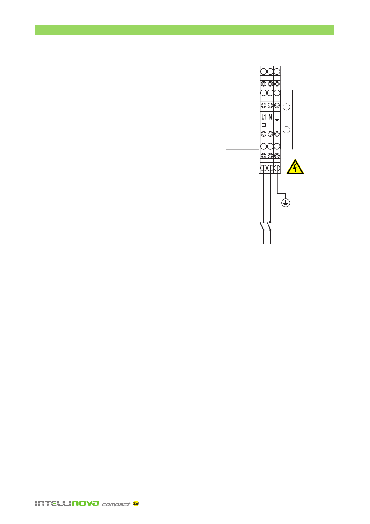
Electrical Installation
Power Supply
The intrinsically safe circuits and Ex i components installed in the
Intellinova®Compact Ex units, those electrical limits crucial to
intrinsic safety must be taken into account.
Signal cables should not be located close to power supply cables.
The System Unit is delivered with an internal power supply unit
(100-240 V AC/50-60 Hz, max. 10 A or 10-36 V DC, 25 W), internal
wiring and terminal blocks for mains power connection.
The supply power should come via an external main power switch,
from a power source with an even load (nominal voltage ± 10%, no
excessive transients). See the figure beside for connection to mains
power terminals. A switch or a circuit breaker must be included in
the installation. It shall be suitable located and easily reached. It
must also be marked with on/off and as the disconnecting device
for the Intellinova®Compact Ex.
Cords shall be rated for the maximum current for the equipment
and the cable used shall meet the requirements of IEC 60227 or
IEC 60245. Cords certified or approved by a recognized testing
authority are regarded as meeting these requirements.
• Make sure that the main power switch is in off position
and will stay off until the work is done. Lock the switch if
possible.
• Open the cable gland and guide the cable end through the
cable entry (A, see page 7).
• Prepare the cable and connect the conductors to the
terminal blocks.
• Tighten the inlet sealing nut with an open-ended 22 mm
spanner, see "Cable gland torque moment” on page 7.
Check that the System Unit is connected to protective earth,
marked with IEC symbol, and that protective earth (PE) is
properly connected to the protective earthing conductor of
the building installation wiring.
100-240 V AC,
50-60 Hz, max. 10 A
or 10-36 V DC, 25 W
L N
Protective
earth (PE)
Main power switch
or circuit-breaker

– 9 –
Electrical Installation
Intrinsic Safety Earth
From the standpoint of intrinsic safety Ex i, insulation must be
made between the equipotential IS-earth bonding conductors
and the PE conductors in the installation. The IS-earth bonding
conductor is regarded as a passive conducting element that fulfils
the required separation conditions with a 500 V insulation test.
The PE conductor, however, is at a certain potential in the event
of a fault, and is regarded as an active, non-intrinsically safe ele-
ment. To fulfil requirement in the ATEX and UKEX directives, the
IS-earth and the PE should be separated.
The minimum cross section of the associated IS-earth protection
conductor is 4 mm².
Network Connection
The System Unit is connected via an RJ45 connector to standard
Ethernet in a LAN network. A shielded network cable should be
used. Consult the responsible network technician prior to con-
necting Intellinova®Compact Ex units to the PC network.
As an option, the Intellinova®Compact Ex units can be equipped
with a network switch to distribute Ethernet to several Intellinova®
Compact Ex units.
• Open the M16 cable gland (D) and guide the cable
through the inlet.
• Mount an RJ45 connector plug on the cable.
• Connect the plug to the RJ45 connector on the circuit
board (pos.2 in the figure on page 6). If an Ethernet switch
(option) is included, connect the LAN network to the switch
(pos. 14 on page 6).
• Tighten the inlet sealing nut with an open-ended 19 mm
spanner, see "Cable gland torque moment” on page 7.
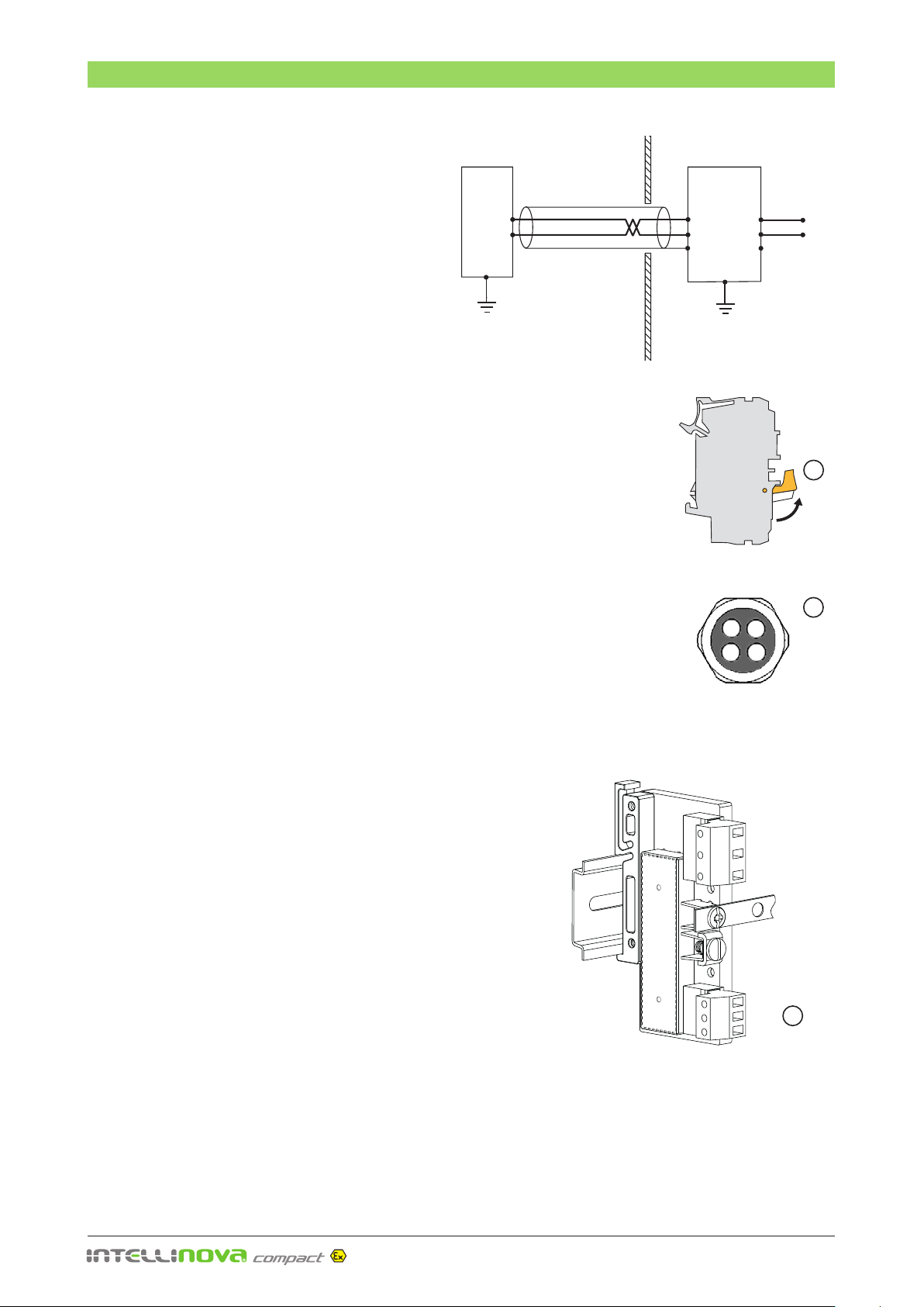
Connection to PC
A PC can be connected to the System Unit via the RJ45 connector
by using a shielded cross-over cable. For communication and set
up the software FSS (Field Service Software) must be installed
and running on the PC.
PE earth
on cabinet
IS-earth terminals
Resistance meter or band
integrity monitor connection
during Earth continuity test
Loop
resistance
<2Ω
Earthing an installation with two conductors
and providing resistance test facilities
D
D
Test Port

– 10 –
Electrical Installation
3
5
1
4
98
2
Power Digital Vibration Bearing Analog Digital
supply inputs monitoring monitoring inputs outputs
6
7
Installations
Electrical signals between safe zone/zone 2 or 22 to
hazardous areas zone 0/20 and 1/21, sensors and out-
puts must be connected to the Intelinova®Compact Ex
thru included Ex interfaces (Ex interface).
All electrical installations located in hazardous zone are
made on the Ex interfaces (Ex interfaces).
The external Ethernet network cable is connected to the
RJ45 connector (3) or if included the Ethernet switch.
When all electrical connections are made, the unit can be
started with the ON/OFF button (1) on the circuit board.
A red LED indicator (2) is lit when power is on.
Status LED Indicators
The circuit board has red status indicators. The LED in-
dicator, OP (4), will alight when the unit is in operational
mode, which means that the power is on and all measur-
ing circuits are running. The indicator, COM (5), is blinking
when the unit communicates via Ethernet.
The red status indicators (6) will alight when the digital
inputs DI/RPM are active and the indicators (7) will alight
when the digital outputs DO are active.
SD Memory Card
The System Unit is equipped with an SD memory card
(8) for data buffering and back-up. This card is also used
for initializing and setup of the System Unit. Reading and
writing to the card is shown by a red LED indicator (9).
Newer remove the SD memory card when power is on.
Digital Inputs
The digital inputs DI/RPM are generally used for speed
measuring with RPM transducers. Two RPM transducers
can be connected and linked to measuring assignments
set up in Condmaster.
Digital Outputs
The unit has three digital outputs DO, for connection
to PLC or via external relays to machine stop, external
warning lamp, etc.
Analog Inputs
The System Unit has three channels for continuous moni-
toring of analog signals AI and measures current from 0
to 20 mA. Measuring units, range, quantities, alarm limits,
etc. are set up in Condmaster.

– 11 –
J1 J2
J3, J4
Bearing Monitoring
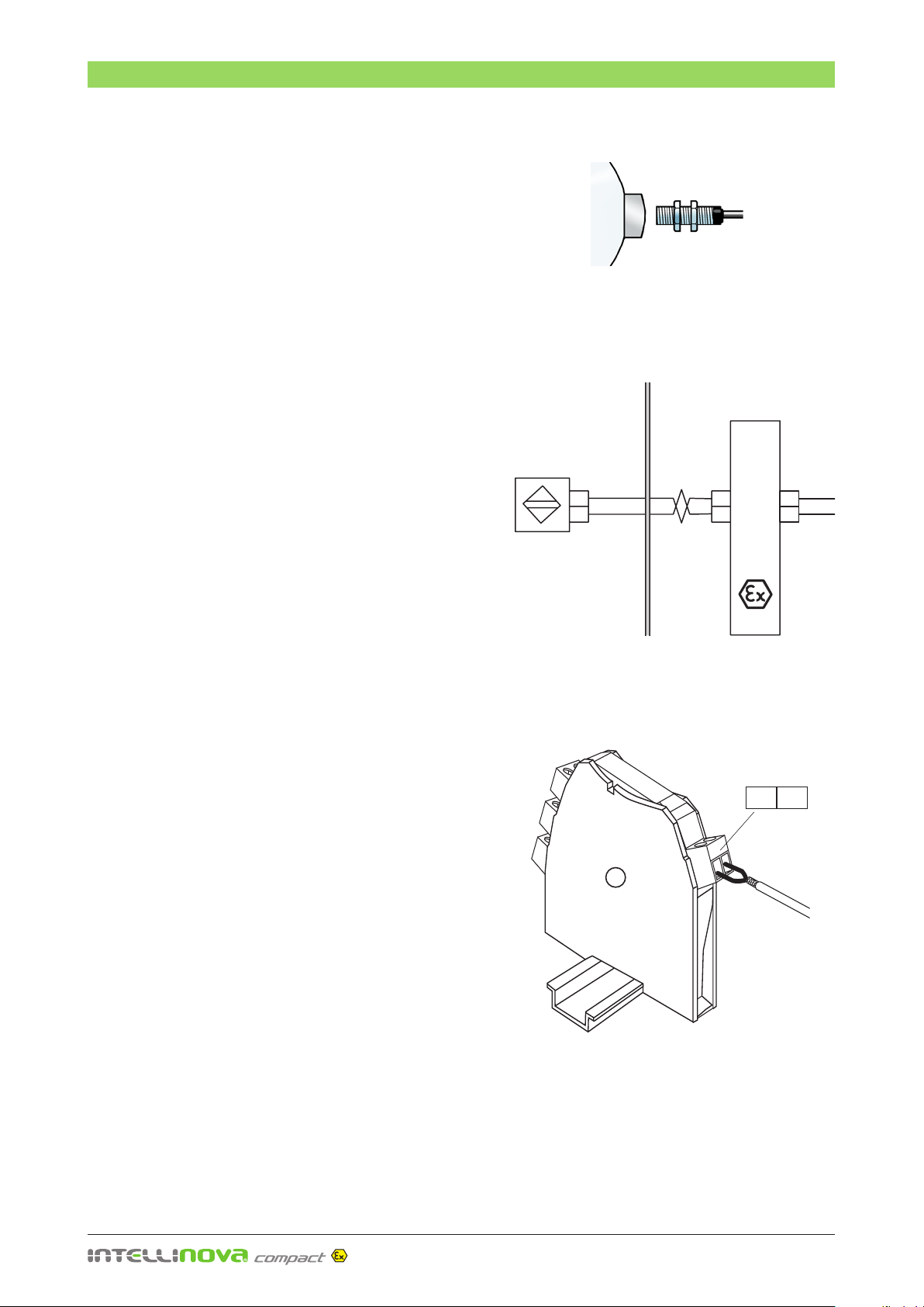
Connection of Shock Pulse Transducers
Shock pulse transducers are connected to the TNC connectors on the
Ex interfaces. See the figures for proper connections.
The cabinet has two cable entries M25x1.5 (1) with rubber insert for
up to 4 measuring cables each, cable diameter 4.5 to 6 mm (IP68).
Unused holes should be sealed with supplied plugs.
Intellinova®Compact Ex INS06Ex units can be delivered fully equipped
with four Ex interfaces for bearing monitoring. If Intellinova®Compact
Ex units are ordered with less than four channels the system can be
updated on site with additional Ex interfaces. Contact SPM Instrument
for update kit including modification instruction.
• Make sure that the System Unit is in power off position.
• Disconnect the power supply by switching off the terminal block
marked L1. Lift the jumper bar (1) as shown in the figure.
• Remove the blanking plug on the M25 cable gland (2) and guide
the cable end through the cable entry.
• Cut the cable and mount TNC connector 93022, see next page.
• Screw the TNC connector firmly into respectively Ex interface (3),
designation SPM1 to SPM4.
• Seal eventually unused inlet holes with supplied plugs and
tighten the gland sealing nuts with an open-ended 33 mm
spanner, see "Cable gland torque moment” on page 7.
• Switch on the terminal block marked L1 by pushing in the jumper
bar (1).
• Perform periodic pressure test according to "Service and Main-
tenance" to check that the enclosure is properly sealed, see
page 19.
Coaxial
cable
2
Shock Pulse
Transducer with
Isolation Foot
Explosive Area Inside nR Enclosure
Ex interface
to circuit
board
Machine
ground
IS-earth
1
3
to circuit
board
TNC input
connector
SPM Transducer Ex interface
17301
rail for
IS-earth
Bearing Monitoring
The System Unit INS06Ex has four channels for con-
tinuous monitoring of bearing condition. It meas-
ures shock pulses according to the SPM®HD method
or the LR/HR HD method. All measuring parameters
such as measuring time, alarm limits, alarm delay,
etc. are set up in the software Condmaster Ruby.
The bearing monitoring channels are connected to
shock pulse transducers of type SPM 44000 Ex via
coaxial cables. The transducers must be fitted with
isolation foot 15862.
Connection to IS-earth
Shock pulse transducers of type 44000 Ex fitted with isolation foot
15862 are isolated from machine ground. The cable shield is con-
nected via the Ex interface to the IS-earth rail inside the system unit.
J1
J2
J3, J4

– 12 –
Mounting TNC Connector 93022
With the cutting tool SPM 81052, a cable is stripped as
follows:
•Cut the cable end with a sharp knife. Push the cutting
tool slide to 5. Put the cable into the tool, with the
end towards the SPM label, level with the centre of
the outer groove.
•Close the tool. Push the slide one step at a time to 1,
rotating the tool several turns for each step. Push the
slide to 5, open the tool, take out the cable.
•Remove the cut-off parts. The two outer bits should
come off easily, exposing 4.5 mm of the inner conduc-
tor and 3.5 mm of the dielectric.
•Slice lengthwise through the remaining bit of insula-
tion, peel it off. Do not damage the braid.
The cut through the insulation should not quite reach the
braid. If two or more strands are cut off the inner conductor,
the pin will not hold when crimped on.
Mount connector 93022 as follows:
•Slide the metal ferrule A onto the cable. With 4 mm
cables, also push the neoprene tube over the cable.
This is best done before stripping the cable.
•Push the contact pin B over the inner conductor and
against the dielectric, with all strands of the inner con-
ductor inside the contact pin. Crimp on the contact
pin.
•Splay out the braid with a conical movement of the
cable end. Push the crimp spigot C under the braid
until the contact pin engages. All strands of the braid
must be on the outside of the spigot.
•Slide the neoprene tube (if used) and ferrule over the
braid and against the connector body. Crimp twice,
first close to the connector body, then again at the
end of the ferrule.
SPM 82166
SPM 81052
Cables with 4 mm diameter
Bearing Monitoring
– 13 –
Vibration Monitoring
2
B
A
J1
1
2
3
J2
1
2
3
–
+
J3, J4
Vibration
Transducer
Explosive Area Inside nR Enclosure
Ex
interface
Shielded TP cable to circuit
board
Machine
ground IS-earth
Connection of Vibration Transducers
Vibration transducers are connected to the input terminals on the Ex inter-
faces. See the figures for proper connections.
Recommended transducers are SPM Instrument SLD200 series transduc-
ers with voltage output.
The optimum cable to use for permanently installed vibration transducers
is a shielded twisted pair. Around the outside of this twisted pair is the
shield. A braided shield is the optimum type of shielding, as it has slightly
better low-frequency shielding capabilities over a foil type of shield. Foil
is often used where RF shielding is necessary.
The cabinet has two cable entries M25x1.5 (1) with rubber insert for up
to 4 measuring cables each, cable diameter 4.5 to 6 mm (IP68). Unused
holes should be sealed with supplied plugs.
Intellinova®Compact Ex INS06Ex units can be delivered fully equipped
with Ex interfaces for two vibration channels. If Intellinova®Compact Ex
units are ordered with less than two channels the system can be updated
on site with additional Ex interfaces. Contact SPM Instrument for update
kit including modification instruction.
• Make sure that the System Unit is in power off position.
• Disconnect the power supply by switching off the terminal block
marked L1. Lift the jumper bar (1) as shown in the figure.
• Remove the blanking plug on the M25 cable gland (2) and guide
the cable end through the cable entry.
• Cut and prepare the conductors.
• Connect the conductors firmly into respectively Ex interface (3),
designation VIB1 and VIB2. Tighten the contact screws.
• Seal eventually unused inlet holes with supplied plugs and tighten
the gland sealing nuts with an open-ended 33 mm spanner, see
"Cable gland torque moment” on page 7.
• Switch on the terminal block marked L1 by pushing in the jumper
bar (1).
• Perform periodic pressure test according to "Service and Mainte-
nance" to check that the enclosure is properly sealed, see page 19.
Vibration Monitoring
The System Unit has 2 channels for continuous
vibration monitoring. It supports broadband vibration
measurement, both ISO 2372 and ISO 10816, plus
FFT with symptoms and EVAM (Evaluated Vibration
Analysis Method). All measuring parameters such
as measuring technique, measuring time, alarm
limits, alarm delay etc. are set up in the software
Condmaster®.
1
to circuit
board
VIB Transducer Ex interface
17310
rail for
IS-earth
Connection to IS-earth
Vibration transducers of type SLD are isolated from machine ground. The cable shield shall be connected in one end
only to the IS-earth rail inside the system unit. The IS-earth terminal on the Ex interface is to be used.
3
input
connector
J1:3
J1:2
J1:1
J4
J3
J2:3
J2:2
J2:1
– 14 –
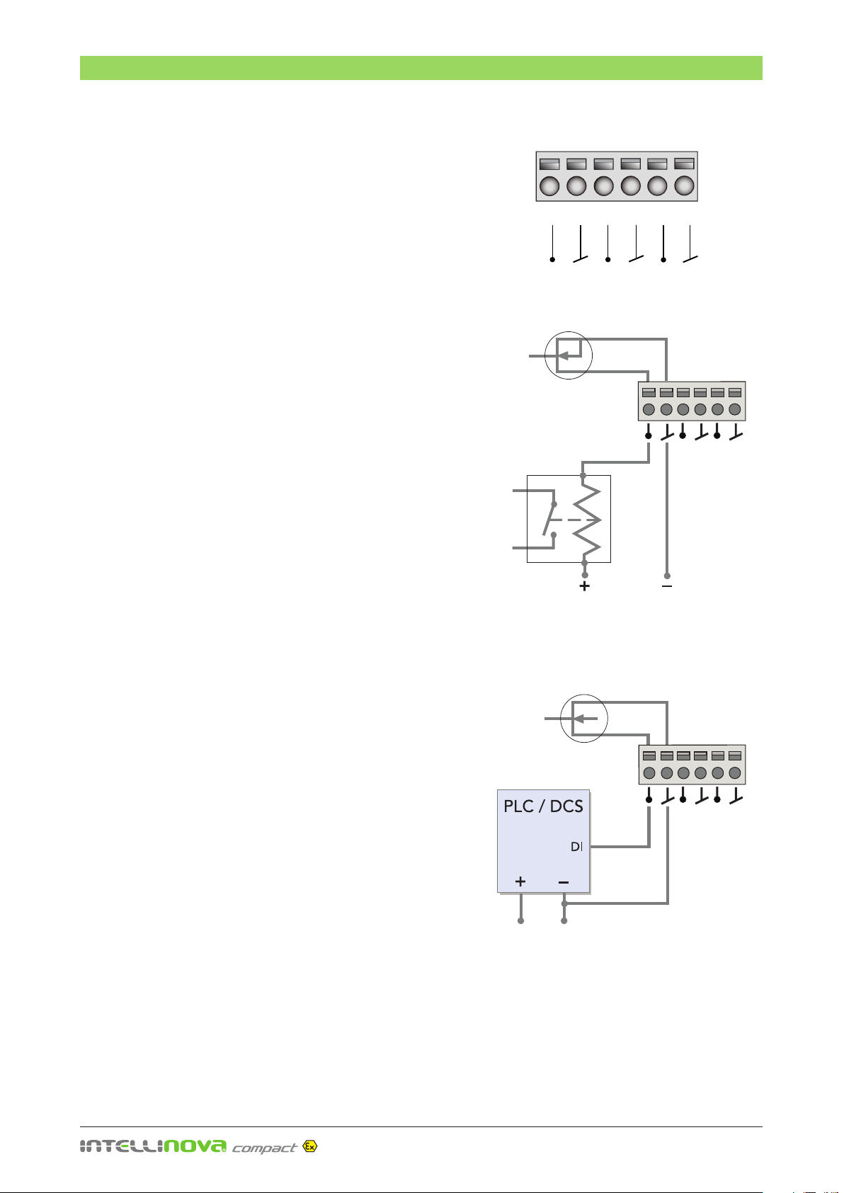
Digital Inputs
Connection of Digital Inputs, DI/RPM
The digital inputs DI/RPM can be used for the connection
of RPM sensors (inductive proximity switches) for speed
measuring. Inductive proximity switches of type NAMUR (DIN
EN 60947-5-6) can be connected to include Ex interfaces.
Recommended inductive proximity switch of type NAMUR
is SPM Instrument part number 90576 or 90577.
A pulse is generated when a metallic object, normally the
shaft key, passes the proximity switch. The number of pulses
per revolution can be specified in Condmaster. One pulse
per revolution is normal.
The proximity switch is mounted close to a rotating machine
part. Adjust the gap between the transducer and the key in
accordance with the manufacturer's instructions. NB. Key
with sharp edges should be rounded as the edges will often
cause two pulses instead of one.
Intellinova®Compact Ex INS06Ex can be delivered fully
equipped with Ex interfaces for two DI channels. Intellinova®
Compact Ex units ordered with less than two channels can be
updated on site with additional Ex interfaces. Contact SPM
Instrument for update kit including modification instructions.
• Make sure that the System Unit is in power off position.
• Open one of the M16x1.5 cable entries (D, see page 7)
and guide the cable end through the cable entry.
• Cut and prepare the conductors.
• Connect the conductors firmly into respectively Ex
interface, designation DI1 to DI2. Tighten the contact
screws.
• Seal unused cable entries with a blanking plug and
tighten the gland nuts with an open-ended 14 mm
spanner, see "Cable gland torque moment” on page 7.
• Perform periodic pressure test according to "Service
and Maintenance" on page 19 to check that the en-
closure is properly sealed.
A red status indicator on the circuit board, next to the termi-
nal block, lights when a DI/RPM channel is active.
Connection of NAMUR sensor to DI/RPM Interface
Inductive proximity switch
DI/RPM
Interface
21
4.24.1
BN
BU
4.24.1
NAMUR
sensor
Explosive Area Inside nR Enclosure
to circuit
board
1
4.1 4.2
– 15 –
Analog Inputs
V- V+
24 VDC/0.75A
LO
ON
Vout ADJ.
100-240 VAC
0.5A
47-63Hz
NL
Connection of Analog Inputs, AI
The System Unit has three channels for continuous moni-
toring of analog signals and measures current from 0 to
20 mA. Measuring units, range, quantities, alarm limits
etc. are set up in Condmaster®.
Connection of analog sensors located in hazardous
areas zone 0 and 1
If Analog sensor is located in Ex hazardous zone 0/20
or 1/21, the Intellinova®System units need to be or-
dered as special. The actual type of sensor intended to
be used must be specified at the time of ordering the
Intellinova®System unit, so that suitable Ex interfaces can
be included.
Connection of analog sensor in safe zone
The cable length may be up to max. 100 m. A 100-ohm
shunt resistor is used for current measurement.
The push-in terminal blocks on the circuit board are
marked with numbers:
AI channel 1 + 20
– 21
AI channel 2 + 22
– 23
AI channel 3 + 24
– 25
Holes for additional cable entries intended for signal ca-
bles to the analog inputs have to be drilled. Drill the holes
in the punch marks on the enclosure with maximum 0.5
mm larger diameter than the cable gland. Cable glands
of type “Ex e” or “Ex t” with suitable size for the cables
must be used. The maximum cable gland size is M20 x1,5.
• Make sure that the system unit is in power off position.
• Disconnect the system unit from the mains power
source. Check with a voltage tester to ensure that the
unit is voltage-free.
• Mount terminal blocks (option SPM Instrument 93380)
on the DIN rail (1).
• Drill holes and mount suitable Ex cable glands on the
enclosure.
• Tighten the inlet sealing nuts. The tightening torques
must be followed by the appropriate manual.
• Open the cable gland and guide the sensor cable
through the inlet.
• Prepare the end of the sensor cable and push the
conductors firmly into respectively terminal.
• When using a shielded cable, connect the shield to
the protective earth terminal block (2) via a short
cable soldered on the shield. The shield should not
be connected to the sensor end.
Analog inputs on circuit board
+ – 4–20mA
Sensor
Protective
earth rail
• Tighten the inlet sealing nut. The tightening torques
must be followed by the appropriate manual.
• Cut and prepare internal single conductor cables as
shown in the figure above (3). Push the cables firmly into
respectively terminal and tighten the contact screws.
• Secure the cables with cable ties mounted on the cable
tie mounting bases.
• Connect the mains power source and switch on the
System Unit with the ON/OFF button.
• Perform periodic pressure test according to "Service
and Maintenance" on page 19 to check that the
enclosure is properly sealed.
1
3
2
20 21 22 23 24 25
+ – + – + –
Ch.1 Ch.2 Ch.3
+ – + – + –
AI
– 16 –
Connection of Digital Outputs, DO
The digital outputs DO can be connected to a PLC/ DCS or
via optional external relays to machine stop, external warning
lamp, etc. The output circuit must not exceed 1 A, 36 V DC.
The circuit is normally open.
Connection of digital output located in hazardous
area zone 0 and 1.
If Digital Output is connected to equipment located in Ex
hazardous zone 0/20 or 1/21, Intellinova®System units need
to be ordered as special. The actual type of equipment
intended to be used must be specified at the time of order
of the Intellinova®System units, so that a suitable IS barrier
can be installed.
Connection of digital output located in safe zone.
The push-in terminal blocks on the circuit board are marked
with numbers:
DO channel 1 38
39
DO channel 2 40
41
DO channel 3 42
43
Holes for additional cable entries intended for signal cables
to the digital outputs have to be drilled. Drill holes in the
punch marks on the enclosure with max. 0.5 mm larger di-
ameter than the cable gland. Cable glands of type “Exe”
or “Ex t” with suitable size for the cable must be used. The
maximum cable gland size is M20x1.5.
• Make sure that the System Unit is in power off position.
• Drill holes and mount suitable Ex cable entries on the
flange.
• Tighten the gland nut. The tightening torque must be
followed by the appropriate manual.
• Open the cable gland and guide the cable end through
the inlet.
• Push the conductors firmly into respectively terminal.
• Tighten the inlet sealing nut. The tightening torque
must be followed by the appropriate manual.
• Perform periodic pressure test according to "Service
and Maintenance" on page 19 to check that the
enclosure is properly sealed.
A red status indicator on the circuit board, next to the termi-
nal block, lights when a DO channel is active.
Digital Outputs
Connection to PLC/DCS (DO 1)
Power Supply
Max.1A,
36 V DC
Relay
Max.1A,
36 V DC
Digital outputs on circuit board
38 39 40 41 42 43
DO1 DO2 DO3
Connection to optional external relay (DO 1)
– 17 –
Configurating Intellinova
SD Memory Card
The System Unit has a built-in SD (Secure Digital) card
reader for 2 GB SD cards (1). The supplied card has been
formatted and can be used immediately.
The SD card is used for the configuration of the System
Unit and establish communication between the unit and
the LinX server, storing measurement task files and buffer-
ing measurement data in case of network malfunctions. It
is also used in situations where Intellinova is used offline,
e.g. onboard ships. A computer with the communication
software LinX and the Field Service Software, FSS, may
be used to load task files from the database onto the SD
card and download measuring results to Condmaster.
This card must not be removed when the System Unit
is in use.
Configuration
Configuration of the System Unit is done in FSS, the
graphical user interface to LinX (also used for field service
and support). LinX is the communication software han-
dling all messages between the Condmaster database
and the Intellinova System Units.
The SD card has to be loaded with necessary setup files
to establish communication between the System Unit
and the LinX server. The SD card is connected to the LinX
computer and the setup is done in FSS. The setup files
are saved to the SD card so that if communication has
been lost, the buffered data will later find its way to the
LinX server.
Before starting the System Unit, all mechanical and elec-
trical installations must be done.
• Place the configured SD card in the SD card reader
(1). Push the card in as far as it will go into the slot
with the contact area facing in and with the chipped
corner on the right side.
• Start up the System Unit with the ON/OFF button
(2). The red LED (3) indicates reading and writing to
the card.
• The COM indicator (4) will blink when the System
Unit communicates with the LinX computer.
• The OP indicator (5) will light when the measuring
circuits are operating.
NB: See the software instruction 'Installing
Condmaster® Ruby" (72094B) with detailed step
by step instructions how to setup the Commander
Unit in the Field Service Software, FSS.
CAUTION
Never remove
the SD card when
power is on
SD card
5
2
4
1
3
– 18 –
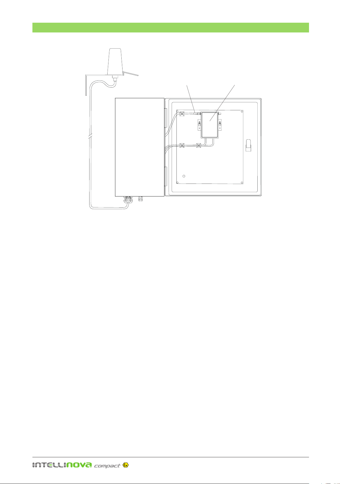
Wi-Fi Ethernet unit
Omni-directional
antenna with
5 m cable Antenna connected
to 'MAIN'
Technical Specifications IND01Ex
Fonctions Ethernet wireless Wi-Fi bridge, bridge router, access Point, repeater (WDS) & virtual cable
Format Universal mounting box (wall and Din Rai)
Dimensions L:103 x W:67 x H:24 mm
Support MODBUS/TCP, PROFINET & Ethernet/IP wireless gateway
Maximum Speed 108 Mbps
Ethernet link 100 Base Tx (RJ45) 10/100 compatible
Radio link Triband wireless Wi-Fi IEEE 802.11a/b/g/h & Super AG
Frequency range 2.4 / 5 / 5.4 GHz
Radio Modem (AD HOC) Bridge mode
Rapid roaming < 50 mS
Antenna connectors RP-SMA
Nominal range 300m, open field (with built-in antennas)
Security WPA-PSK, WPA2-PSK, WEP 64/128 bits, IEEE 802.1X (RADIUS) MAC addresses filtering
SSID broadcast control
Number of Wi-Fi clients 30 (in AP mode)
Administration Web browser SNMP, ACKSYS NDM
Power supply +9VDC to +48VDC, 3-point PHOENIX connector
Power consumption 3.5W typical
The option IND01Ex includes a wireless Ethernet unit
mounted on the cabinet lid and internal wiring. An ex-
ternal omni-directional antenna and a 5 m antenna cable
are included.
The System Unit is connected via a 10/100 Ethernet
switch on the Wi-Fi Ethernet unit. For configuration of
the Wi-Fi unit, see the user guide from the manufacturer
(ACKSYS DTUS061).
WirFi Ethernet Unit (Option)
Inside of the lid
Table of contents
Other SPM Measuring Instrument manuals

SPM
SPM VibChecker User manual

SPM
SPM Machine Guard MG4-REF11A User manual

SPM
SPM A2010 User manual

SPM
SPM intellinova parallel MB INS MB 4V Owner's manual

SPM
SPM Vibrameter VIB-11B User manual

SPM
SPM VibChecker User manual

SPM
SPM Intellinova Compact User manual

SPM
SPM leonova emerald User manual

SPM
SPM VIB-11 User manual
Popular Measuring Instrument manuals by other brands

Steiner
Steiner M830r LRF instruction manual

Black & Decker
Black & Decker ATM100 instruction manual

SATO KEIRYOKI
SATO KEIRYOKI PC-5400TRH instruction manual

Graytechnos
Graytechnos photom MiNi 219 instruction manual

Analog Technologies
Analog Technologies ALDD28V5A401 quick start guide

Abaxis
Abaxis Piccolo Xpress AB-801-110-0000 Quick reference guide


