SPM SUPERCOLD 12 LT User manual

Codice n°/
Code N
°
/ Code n°/
Codenummer
/ N°de código
:SC220110/5060 ALL
Edizione /
Edition
/ Edition /
Ausgabe
/ Edición : 07/2002
SUPERCOLD 12 LT
SUPERCOLD 20 LT
SUPERCOLD 12+12 LT
MANUALE DI ISTRUZIONI
INSTRUCTION MANUAL
MANUEL D'INSTRUCTIONS
BEDIENUNGSANLEITUNG
MANUAL DE INSTRUCCIONES
DRINK SYSTEMS s.r.l.
ATTREZZATURE BAR
DISTRIBUTORE PRE-MIX DI BEVANDE FREDDE
PRE-MIX COLD DRINK DISPENSER
DISTRIBUTEUR PRE-MIX DE BOISSONS FROIDES
PRE MIX-AUSGABEGERÄT FÜR KALTE GETRÄNKE
DISTRIBUIDOR PRE-MIX DE BEBIDAS FRIAS

1
ITALIANO pag. 3
ENGLISH page 13
FRANÇAIS page 23
DEUTSCH Seite 33
ESPAÑOL pág. 43

2

3
Gentile Cliente,
ci congratuliamo con Lei per aver scelto un prodotto di qua-
lità che sicuramente risponderà alle Sue aspettative.
RingraziandoLa per la preferenza accordataci, la invitiamo
cortesemente a prendere attenta visione del presente ma-
nuale istruzioni prima di utilizzare la Sua macchina
Supercold 12 lt / Supercold 20 lt.

4
INDICE
1AVVERTENZE E CONSIGLI
IMPORTANTI pag. 5
2INDICAZIONI UTILI PER IL
TRASPORTO pag. 5
3INSTALLAZIONE pag. 5
4COLLEGAMENTO ALLA RETE
ELETTRICA pag. 6
5FUNZIONAMENTO pag. 7
6OPERAZIONI DI PULIZIA pag. 8
7MANUTENZIONE STRAORDINARIA pag. 10
8SCHEMA ELETTRICO pag. 11

5
1 - AVVERTENZE E CONSIGLI IMPORTANTI
Il presente manuale istruzioni è parte integrante di
Supercold e dovrà esserlo per qualsiasi consultazione.
Leggere attentamente le avvertenze contenute nel pre-
sente manuale di istruzioni prima di installare ed utiliz-
zare Supercold.
Questo manuale, oltre ad informare sulla manutenzione
ordinaria di Supercold ed a supportare i tecnici nella
ricercaenellariparazionedeglieventualiguasti,sipone
come obiettivo il massimo sfruttamento della potenzia-
lità della macchina, al fine di poterla adattare alle esi-
genze dei vari paesi dove si andrà ad utilizzare.
Modificare o tentare di modificare questo apparecchio,
oltre a fare decadere qualsiasi forma di garanzia, è
estremamente pericoloso.
E' necessario che le operazioni di manutenzione venga-
no effettuate da personale professionalmente qualifica-
to; non tentare mai di ripararlo da soli poiché l'interven-
to di persone non competenti, oltre ad essere pericolo-
so, può causare dei gravi danni.
2 - INDICAZIONI UTILI PER IL TRASPORTO
Al fine di evitare che l’olio contenuto nel compressore
defluisca nel circuito refrigerante, è necessario trasportare,
immagazzinare e movimentare in posizione verticale
rispettando le indicazioni poste sull’imballo.
3 - INSTALLAZIONE
a) Liberare l'apparecchio dall'imballo, quindi sfilarlo dall'al-
to.
b) Posizionamento
-fare in modo che la carrozzeria della macchina sia
ben aerata ed evitare di installarla vicino a punti di ca-
lore; si consiglia temperature ambiente tra i 15 ed i 25
°C.

6
Prima di inserire la spina nella presa di alimentazione
è necessario che, per la Vs. sicurezza, prendiate atten-
ta visione delle seguenti precauzioni.
-La sicurezza elettrica di questo apparecchio è raggiunta
soltanto quando lo stesso è correttamente collegato ad
un efficace impianto di messa a terra, eseguito come pre-
visto dalle vigenti normative nazionali di sicurezza. Il
costruttore non può essere quindi considerato responsa-
bile per eventuali danni causati dalla mancanza di messa
a terra dell'impianto.
-E' indispensabile predisporre, per una corretta e sicura
installazione una apposita presa comandata da un inter-
ruttore unipolare con distanza di apertura dei contatti ugua-
le o superiore a 3 mm, conforme alle vigenti normative
nazionali di sicurezza.
- Accertarsi che il cavo di alimentazione, per tutta la sua
lunghezza, non venga in nessun modo schiacciato. Non
usare prolunghe e, per staccare la spina, afferrare la stes-
sa effettuando trazione dolce, dopo azionato (staccato)
l'interruttore.
-Non ostruire le griglie di ventilazione e di dissipazione del
calore in quanto una cattiva aerazione, oltre a determina-
re la diminuizione di rendimento ed un cattivo funziona-
mento, può provocare seri danni all'apparecchio.
4 - COLLEGAMENTO ALLA RETE ELETTRICA

7
5 - FUNZIONAMENTO
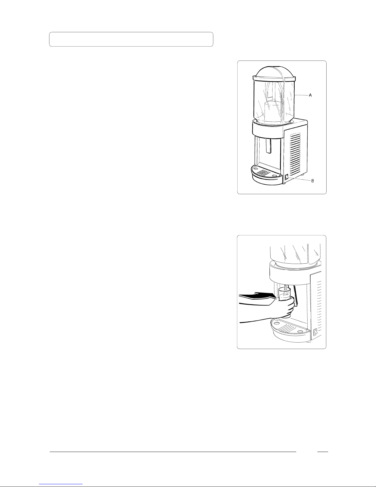
-Introdurre il prodotto nella vasca (A) ed accendere la
macchina tramite l'interruttore (B) - fig. 1.
-Per erogare il prodotto, collocare un bicchiere sotto il
rubinetto e spingere la relativa leva verso l'interno (fig. 2).
Fig. 2
Fig. 1

8
Fig. 5
Fig. 3
Fig. 4
6- OPERAZIONI DI PULIZIA
-Smontare la vasca (A) dalla propria sede spingendola ver-
so l'alto come raffigurato in fig. 3.
-Estrarre la pala mescolatrice (C) tirandola verso l'alto (fig.
4).
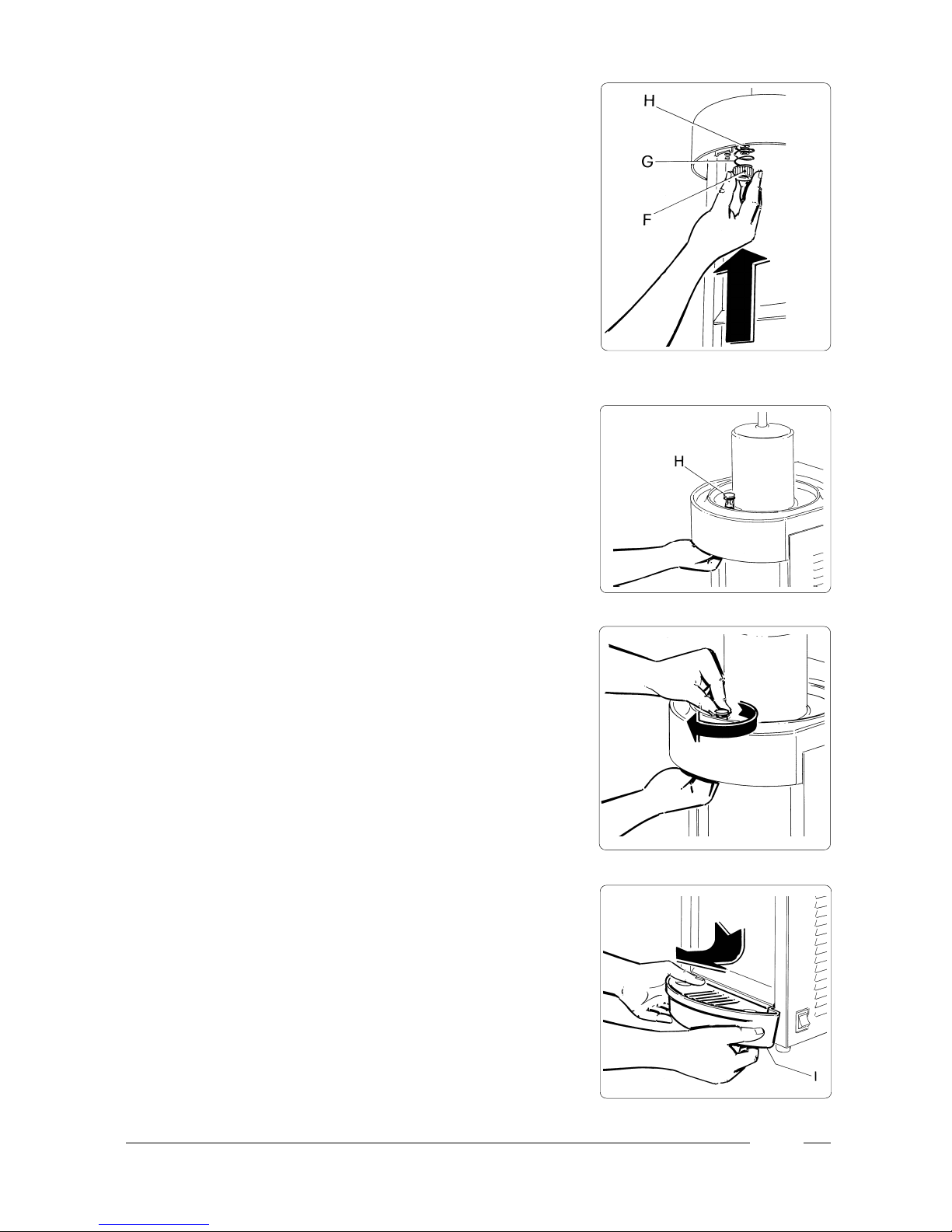
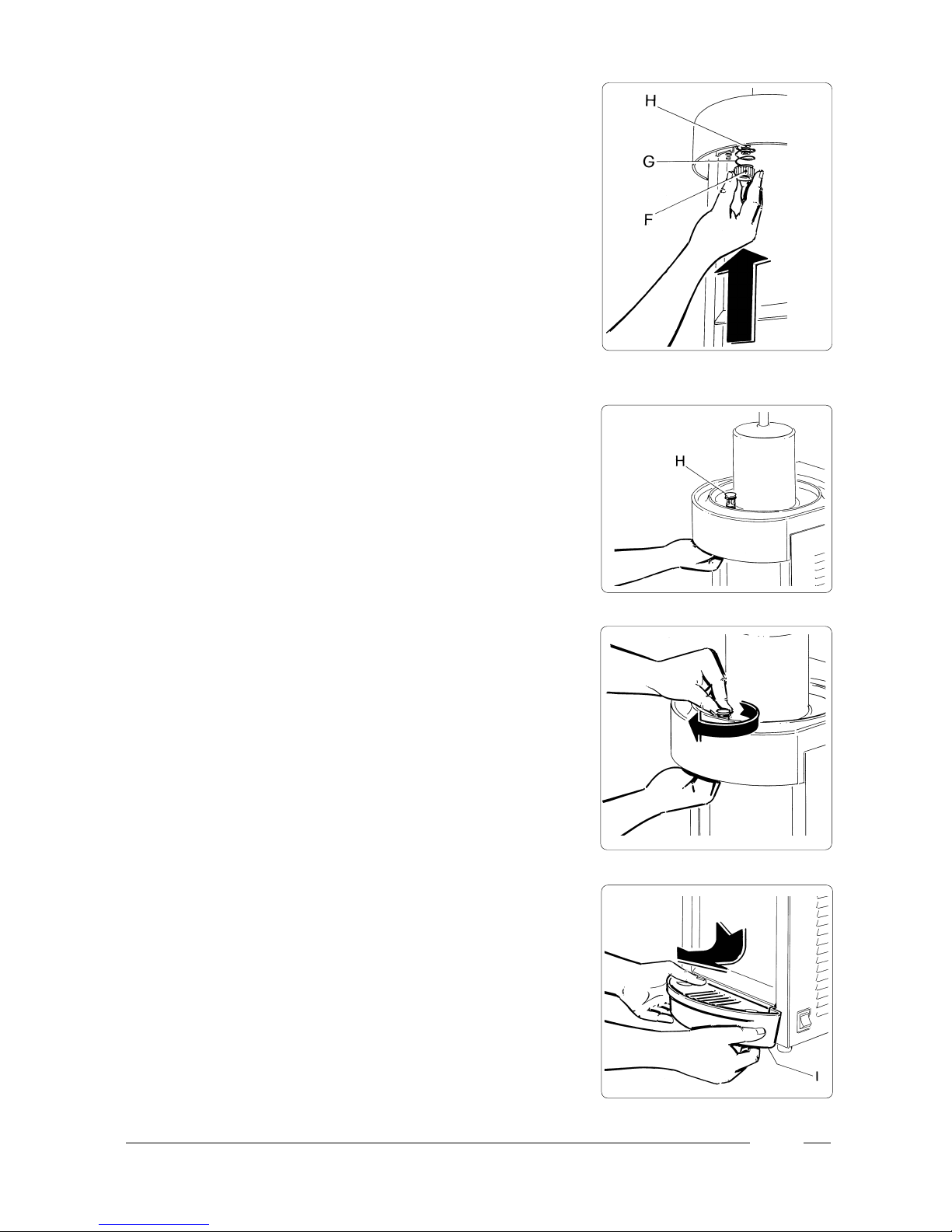
-Smontare il rubinetto in sequenza (fig. 5): svitare il pomel-
lo (D), estrarre la leva (E), svitare la rondella dentata (F) e
la molla (G) dopodichè estrarre dalla parte superiore la
boccola (H).
-Pulire dettagliatamente la vasca (A), la pala mescolatrice
(C) e tutti i componenti che formano il rubinetto, con ac-
qua calda e detersivo per le stoviglie.
➤
HG
9
Fig. 6
Fig. 8
-Per il rimontaggio del rubinetto procedere come segue (fig.
6,7 e 8):
- collocare la boccola (H) dalla parte superiore;
- dalla parte inferiore collocare la molla (G) e la rondella
dentata (F) spingendola verso l'alto e nel medesimo tem-
po avvitandola in senso orario.
-Per il rimontaggio della pala mescolatrice (C) appoggiarla
sopra al proprio albero di rotazione senza esercitare forza
eccessiva.
-Per il rimontaggio della vasca (A) inumidire con acqua la
guarnizione della vasca e spingerla con due mani dalla
parte superiore verso il basso in modo che si allinei com-
pletamente con la sua sede.
-Per estrarre la vaschetta raccogligocce alzare leggermen-
te la parte frontale e sfilarla verso l'esterno (fig. 9).
Fig. 7
Fig. 9

10
Fig. 10
7 - MANUTENZIONE STRAORDINARIA
Al fine di ottenere un buon rendimento del gruppo frigorifero,
si raccomanda una volta al mese di pulire il condensatore
della macchina (fig. 10).

11
Fig. 11
8 - SCHEMA ELETTRICO
- Legenda schema elettrico
INT) Interruttore generale
V) Ventilatore
MR1) Motoriduttore 1
MR2) Motoriduttore 2
T1) Termostato 1
T2) Termostato 2
C) Compressore
R) Relé compressore
CS) Condensatore di spunto completo
PT) Protettore termico compressore
INT
NL
MR1 MR2 T1 T2
PT
C
R
CS
V
Ø
2
1

12

13
Dear Client,
we would like to congratulate you for having chosen a high
quality product which will surely meet all your expectations.
While thanking you for the preference you have given us,
we invite you to carefully read the following instruction
manual before operating your Supercold 12 lt / Supercold
20 lt.

14
INDEX
1IMPORTANT WARNINGS AND
SUGGESTIONS page 15
2USEFUL INSTRUCTIONS FOR
TRANSPORT page 15
3 INSTALLATION page 15
4CONNECTION TO POWER SUPPLY
MAINS page 16
5OPERATING PROCEDURE page 17
6CLEANING PROCEDURE page 18
7SELECT MAINTENANCE page 20
8WIRING DIAGRAM page 21

15
3 - INSTALLATION
a) Remove the packing material from the machine, then slide
it off from the top.
b) Positioning the machine
-the main body of the machine must be well ventilated.
Installation of the machine near a heat source should
be avoided. A room temperature between 15 °C and
25 °C is suggested.
1 - IMPORTANT WARNINGS AND SUGGESTIONS
The present instruction manual is an important part of
the Supercold and must be kept for any future
consultation.
Carefully read the warnings contained in this instruc-
tion manual before installing and operating the
Supercold.
Besides providing information on routine maintenance
of the Supercold and aiding the technical assistants in
the detection and repair of possible malfunctions, the
objective of this manual is to take advantage of the
maximum potentials of the Supercold in order to adapt
the machine to the specific needs of the various coun-
tries where it will be used.
Modification of, or any attempt to modify this machine,
is extremely dangerous and will cancel any form of
warranty.
All maintenance procedures must be performed by
expertly qualified personnel.
The attempt to repair the machine by unqualified per-
sons is dangerous and may cause serious damage to
the machine.
2 - USEFUL INSTRUCTIONS FOR TRANSPORT
In order to prevent the oil contained in the compressor from
flowing into the cooling circuit, it is necessary to always carry,
store and handle the Supercold in a vertical position,
following the instructions found on the packaging.

16
For your personal safety, before inserting the plug into
the electrical outlet carefully read the following pre-
cautions.
-The electrical safety of Supercold can only be achieved if
the machine is properly connected to an efficient ground-
ing system, in compliance with current national safety
standards. Therefore, the manufacturer cannot be held
responsible for damage and/or injury caused by failure to
properly ground the machine.
-For a safe and correct installation, it is necessary to pro-
vide for a special outlet, with contacts having an open dis-
tance equal to or greater than 3 mm, controlled by an uni-
polar circuit breaker, conforming to current national secu-
rity standards.
-The power supply cable must not, in any way, for its entire
length, be compressed, extension cords may not be used,
and finally, the plug must be removed from the outlet with
a slight pulling movement, after having first cut-off the
power supply.
-Do not obstruct the ventilating grill and heat dispersion
grill, since an insufficient ventilation may not only reduce
the efficiency of the machine, causing it to function inad-
equately, but may also cause serious damage to the ma-
chine.
4 - CONNECTION TO POWER SUPPLY MAINS
17
5 - OPERATING PROCEDURE
-Pour the product into the bowl (A) and turn on the machine,
using the switch (B) - fig. 1.
-To dispense the product place a cup under the tap and
press the relevant lever inward (fig. 2).
Fig. 2
Fig. 1

18
Fig. 5
Fig. 3
Fig. 4
6- CLEANING PROCEDURE
-Remove the bowl (A) from its place by pushing it upward,
as shown (fig. 3).
- Remove the mixing blade (C) by pulling it upward (fig. 4).
-Disassembling the tap (fig. 5): unscrew the knob (D), re-
move the lever (E), unscrew the toothed washer (F) and
the spring (G) then remove the ferrule (H) from the upper
part.
-Carefully clean the bowl (A), the mixing blade (C) and all
part of the tap using hot water and dishwashing detergent.
➤
HG
19
Fig. 6
Fig. 8
-To reassemble the tap, proceed as follows (fig. 6,7 and 8):
- place the ferrule (H) in the upper part;
- in the lower part place the spring (G) and the toothed
washer (F) pushing the washer upward while screwing it
clockwise.
-To reassemble he mixing blade (C) place it on its rotating
shaft, without exerting too much pressure.
-To reassemble the bowl (A), moisten the bowl gasket with
water, then press it down on the upper part, using both
hands, so that it is completely aligned in place.
-To remove the liquid drip tray, slightly lift the front part,
then pull it outward (fig. 9).
Fig. 7
Fig. 9
This manual suits for next models
2
Table of contents
Languages:
Other SPM Water Dispenser manuals


Popular Water Dispenser manuals by other brands

AAFIRST
AAFIRST EZYTAP75 Installation and operating instructions

Morphy Richards
Morphy Richards BRITA WATER FILTER KETTLE instructions

Avalon
Avalon A6BLWTRCLRWHT user manual

Whirlpool
Whirlpool WHES48 Installation and operation manual

Kenmore
Kenmore 625.384600 owner's manual

Halsey Taylor
Halsey Taylor HAC-Q Series quick start guide


