manuals.online logo
Brands
  1. Home
  2. •
  3. Brands
  4. •
  5. Crystal Mountain
  6. •
  7. Water Dispenser
  8. •
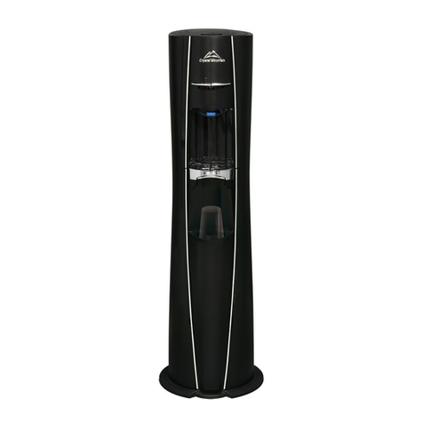
  9. Crystal Mountain Mogul User manual

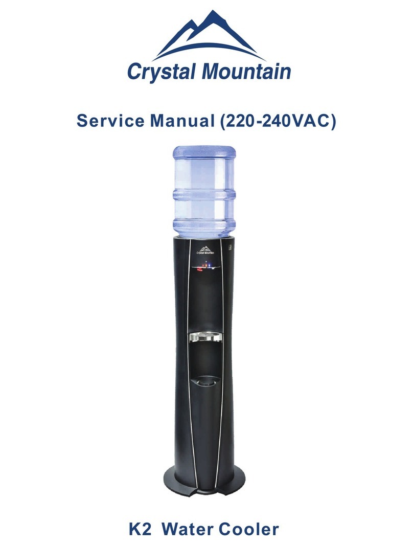
Crystal Mountain Mogul User manual

5- 1
Removal and Installation
Notice:
The information and/or procedures presented in the following demonstration(s) should be performed by a trained Water Cooler Service Technician only.
Never attempt to service or repair a water cooler while it is plugged into any power supply.
Prior to any service or repair of the water cooler, ensure that the water has been completely drained from the system.
. Crystal Guard Removal & Installation Procedure
REMOVAL
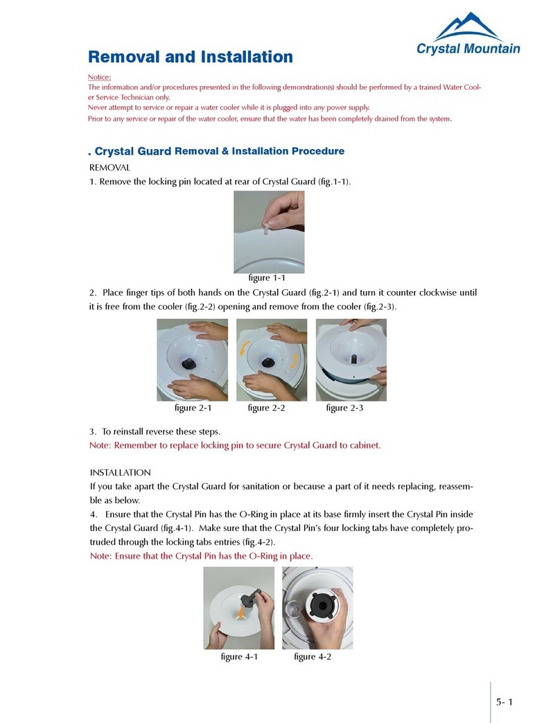
1. Remove the locking pin located at rear of Crystal Guard (figure 1-1).
2. Place finger tips of both hands on the Crystal Guard (figure 2-1) and turn it counter clockwise until it is free from the
cooler (figure 2-2) opening and remove from the cooler (figure 2-3).
3. To reinstall reverse these steps.
Note: Remember to replace locking pin to secure Crystal Guard to cabinet.
INSTALLATION
If you take apart the Crystal Guard for sanitation or because a part of it needs replacing, reassemble as below.
4. Ensure that the Crystal Pin has the O-Ring in place at its base firmly insert the Crystal Pin inside the Crystal Guard (figure 4-1). Make
sure that the Crystal Pin’s four locking tabs have completely protruded through the locking tabs entries (figure 4-2).
Note: Ensure that the Crystal Pin has the O-Ring in place.
5. Using the Crystal Guard removal tool (SMT-C000110) to insert clean pin in guard (figure 5-1). Twist the Crystal Pin
clockwise until the four locking tabs are approximately half way between the four holes (figure 5-2).
figure 1-1
figure 2-1 figure 2-2 figure 2-3
figure 4-1 figure 4-2
figure 5-1 figure 5-2
5- 2
9. Re-install the Crystal Guard onto cooler. The Crystal Guard system was designed to seal air and therefore
the guard will fit very tightly when installed with the blue gasket (figure 9-1).
10. Poke the arrow pin used to lock the Crystal Guard down through its drilled hole to secure the lid on the
cooler (figure 10-1).
6. Insert the floater into the cylindrical toothed part on the backside of the Crystal Guard (figure 6-1).
Note: Make sure that once installed, the floater can move freely up and down inside the cylinder.
7. Insert the air filter cap over the floater and on the cylindrical toothed area of the Crystal Guard until it bot-
toms out (figure 7-1)(figure 7-2).
8. Insert the blue gasket into the gasket groove area of the Crystal Guard until it bottoms out (usually this gasket
is applied to the guard by the factory as a sub assembly) (figure 8-1). Make sure that the gasket is depressed so
that it is below the level of the gasket groove to allow ease of assembly (figure 8-2).
Note: The reservoir also can be used as a tool to press the gasket into the groove (figure 8-3).
figure 9-1
figure 10-1
figure 6-1
figure 8-1 figure 8-2 figure 8-3
figure 7-1 figure 7-2
5- 3
1. Remove the water bottle (figure 1-1) and drain water from the reservoir (figure 1-2) and hot tank, remember-
ing to cool and drain hot tank. Allow 2 hours for hot water to cool down inside the hot tank before removing the
drain plug at the rear of the cooler to drain into a bucket.
2. Use the fingertips of both hands to press on the Crystal Guard and turn counter clockwise till it is free from
the cooler opening (figure 2-1).
3. Use fingers of both hands to lift up and remove the insulation jacket covering the reservoir, from the cooler
opening (figure 3-1).
4. Remove baffle cup (figure 4-1) and unscrew baffle stem and wingnut (figure 4-2) (figure 4-3). During reinstal-
lation, tighten to 30 kgf.cm.
5. Approach the cooler from the rear. Open the latch provided on the evaporator band (figure 5-1).
. E & S Series Reservoir Removal Procedure
figure 1-1 figure 1-2
figure 2-1
figure 3-1
figure 4-1 figure 4-2 figure 4-3
figure 5-1
5- 4
figure 6-1
6. Use both hands to loosen the reservoir from the evaporator band and lift it straight through the cooler opening (figure 6-1).
. DryGuardTM Removal & lnstallation Procedure
REMOVAL
1. Remove the bottle (figure 1-1) and Outer DryGuardTM Cover (figure 1-2) from the cooler.
2. Approaching the cooler from the side, place one palm onto the top of the cooler on the side furthest from you, and us-
ing your thumb, press downwards on the reservoir Insulation (figure 2-1).
3. Using your other hand, grip the edge of the Inner DryGuardTM Cone and pull it up slowly to remove (figure 3-1).
Note: DryGuardTM is designed to fit very tightly into reservoir.
INSTALLATION
4. Place the Inner DryGuardTM assembly onto the center of the cold water reservoir; make sure the filter cap is pointed
towards the rear of the cooler (figure 4-1).
figure 1-1 figure 1-2
figure 2-1
figure 3-1
figure 4-1
5- 5
5. Using the palms of both hands, push the DryGuardTM straight down into the reservoir (figure 5-1) (figure 5-2).
6. Install the Outer DryGuardTM Cover onto the cooler (figure 6-1) and lock into place by turning clockwise (figure 6-2).
figure 6-1 figure 6-2
figure 5-1 figure5-2
1. Unplug cooler from power source (figure 1-1).
2. Empty and remove water bottle (figure 2-1) and drain cooler reservoir through the faucets until empty (figure 2-2).If
cooler is a hot and cold, the hot tank must be drained from the drain plug located on the back of unit on the lower right
side (figure 2-3). Also, shut hot tank switch off.
CAUTION
The water in the hot tank is very hot; after unplugging cooler, allow 2 hours for water to cool down before removing the
drain cap to drain the system!
3. Remove top lid of cooler by turning counter clockwise or to the left (figure 3-1). For Crystal Guard , remove the
Crystal Guard pin stopper at rear of outer edge of guard or ring (figure 3-2).
figure 1-1 figure 2-1 figure 2-2 figure 2-3
. Refrigeration Repair System(RRS) Removal Procedure
figure 3-1 figure 3-2
5- 6
4. Turn cooler around so you are facing the back of the unit, and remove the top of the two piece blue, or white, in-
sulation by lifting it straight up through the cooler top opening (figure 4-1). Bottom insulation piece remains on cooler.
5. If cooler is equipped with a white aluminum evaporator (cooling band), loosen (figure 5-1) and unhook (figure
5-2) the latch and catch from the band and pull the band back away from reservoir towards the back of cooler cabinet.
If cooler is equipped with a copper tubing evaporator, there is no latch system to unhook.
6. Remove faucets by turning counter clockwise (figure 6-1), remove baffle cup (figure 6-2) and unscrew baffle stem
(figure 6-3) and wing nut (figure 6-4) inside reservoir. Mark a vertical line on the outside of the reservoir across evapo-
rator (figure 6-5), so when re-installing the reservoir will be lined up as it is presently.
7. Hold the evaporator down and press the reservoir up and out of the evaporator cooling coil (figure 7-1).
At this point it is advisable to put the cooler on a bench or table to make it easier to access components.
figure 4-1
figure 5-1 figure 5-2
figure 6-1 figure 6-2 figure 6-3 figure 6-4 figure 6-5
figure 7-1
5- 7
8. Remove the 4 screws that secure the metal top and bottom plate, 2 on top (figure 8-1) and 2 on the bottom (the
outside screws)(figure 8-2). Leave the 4 screws that hold the black grill to the top & bottom plate secure.
9. The RRS system is now ready to be slid out of the plastic cabinet.
10. Hold the condenser on the right hand side and slowly lift and pull to free the RRS system from the cooler body. Slowly
work the unit from top to bottom until it starts to slide out. Once it starts to come out, be careful of the small capillary tube
(copper coil) located on the left side of the compressor as it is very fragile (figure 10-1), guide it by the cooler body with
your hand. Then slide the unit as far as possible to the left and the support stick on the right side will come by the body (figure
10-2). Continue until the RRS is outside the cooler body and free standing on its own (figure 10-3).
figure 8-1 figure 8-2
figure 10-1 figure 10-2 figure 10-3
. Replacing Hot Tank Auto Cutout & Manual Reset Procedure
Note: Begin with the unit unplugged, water drained and the refrigeration system removed from the cabinet.
Tip: Use a small flathead screwdriver to pry wire connectors off.
1. Remove the wire connectors from the top and bottom of the thermostat to be changed and identify (figure 1-1).
Remove the two screws and remove the thermostat from the bracket (figure 1-2).
2. There is enough heat transfer paste on the tank and old thermostat to simply wipe the face of new thermostat
against the old one (figure 2-1). Place into position and evenly tighten the two screws (torque to 3.4-6.9 lbf.in) (figure
2-2 to 2-4).
figure 1-1 figure 1-2
figure 2-1 figure 2-2 figure 2-3 figure 2-4
5- 8
figure 3-1
. Hot Tank & Heater Assembly Replacement Procedure
Removal
1. Remove Refrigeration System (Refer to RRS Removal Procedure)
2. Stand the RRS system on a bench or table for easier access to components.
3. Remove drain assembly from condenser (black grill) at back of unit (figure 3-1).
4. Unplug wire connector from manual reset on hot tank (figure 4-1)
5. Unplug wire connector from heater that goes down to compressor (figure 5-1).
6. Remove screw and ground wire from hot tank bracket (figure 6-1).
figure 3-1
figure 4-1
figure 5-1
figure 6-1
3. Reconnect the wires onto the thermostat as identified (figure 3-1).
5- 9
7. Hold the hot tank assembly with one hand while removing the 2 screws that hold the hot tank support bracket on the
back of the condenser (figure 7-1). Lift the bottom reservoir insulation slightly and slide tank down and out..
Installation
8. Install the new tank assembly in the reverse order as the above instructions. The tank height is determined by the gas-
ket on the hot tank inlet, it should be even with the insulation indent where the reservoir will rest (figure 8-1). The sup-
port bracket screws should be fastened in the same location on the condenser, as before disassembly. Do not over tighten
these screws to the condenser, as you could break the condenser cooling fins.
figure 8-1
figure 7-1
. Replacing Compressor Relay & Overload Procedure
Note: Begin with the unit unplugged, water drained and the refrigeration system removed from the cabinet.
Tip: Use a small flathead screwdriver to pry wire connectors and relay from compressor.
1. Remove the relay/overload cover by prying the metal clip to unhook it from the compressor on both sides (figure 1-1
and 1-2).
2. Carefully remove and identify the wire connectors from the relay (white wires) and/or overload (black wire) (figure 2-1
and 2-2). Remove relay and overload from compressor (figure 2-3 and 2-4).
figure 1-1 figure 1-2
figure 2-1 figure 2-2 figure 2-3 figure 2-4
5- 10
3. Install the new overload onto the top pin of the compressor (figure 3-1) and push the new relay onto the two bot-
tom pins below the overload (figure 3-2). Reconnect the white wires onto the relay (figure 3-3) and the black wire
onto the overload (figure 3-4).
4. Reinstall the cover and secure with the metal clip (figure 4-1 and 4-2). Note: use caution not to damage wires.
figure 3-1 figure 3-2 figure 3-3 figure 3-4
figure 4-1 figure 4-2
. Hot Tank Heater Replacement Procedure
1. Remove Refrigeration System (Refer to RRS Removal Procedure).
2. Stand RRS system on bench or table for easier access to components (figure 2-1).
3. Unplug wire connector from heater band that goes to the manual reset, which is mounted along with the auto
cutout, in the bracket directly above the heater tightening screw (figure 3-1).
4. Unplug wire connector from heater band that goes down to the compressor (figure 4-1).
5. Loosen and remove tightening screw that secures heater band to the hot tank (figure 5-1) and slide heater down
(figure 5-2) and over support bracket and drain tube.** Save the heater band film that is between the heater and
tank and re-use with the new heater.
6. Install new heater in the reverse order
Note: Push the manual reset button in before re-assembling unit.
figure 2-1 figure 3-1
figure 4-1 figure 5-1 figure 5-2

Other manuals for Mogul

3

Other Crystal Mountain Water Dispenser manuals

Crystal Mountain CMFIWD001 User manual

Crystal Mountain

Crystal Mountain CMFIWD001 User manual

Crystal Mountain K2 User manual

Crystal Mountain

Crystal Mountain K2 User manual

Crystal Mountain Avalanche User manual

Crystal Mountain

Crystal Mountain Avalanche User manual

Crystal Mountain GLACIER User manual

Crystal Mountain

Crystal Mountain GLACIER User manual

Crystal Mountain ASPEN User manual

Crystal Mountain

Crystal Mountain ASPEN User manual

Crystal Mountain Storm Cafe Configuration guide

Crystal Mountain

Crystal Mountain Storm Cafe Configuration guide

Crystal Mountain Storm User manual

Crystal Mountain

Crystal Mountain Storm User manual

Crystal Mountain Blizzard User manual

Crystal Mountain

Crystal Mountain Blizzard User manual

Crystal Mountain Everest Elite User manual

Crystal Mountain

Crystal Mountain Everest Elite User manual

Crystal Mountain STORM Bottom-Load User manual

Crystal Mountain

Crystal Mountain STORM Bottom-Load User manual

Crystal Mountain Mogul User manual

Crystal Mountain

Crystal Mountain Mogul User manual

Crystal Mountain Summit User manual

Crystal Mountain

Crystal Mountain Summit User manual

Crystal Mountain Crystal Pro Owner's manual

Crystal Mountain

Crystal Mountain Crystal Pro Owner's manual

Crystal Mountain Mogul User manual

Crystal Mountain

Crystal Mountain Mogul User manual

Crystal Mountain EVEREST User manual

Crystal Mountain

Crystal Mountain EVEREST User manual

Crystal Mountain Standup Series User manual

Crystal Mountain

Crystal Mountain Standup Series User manual

Crystal Mountain Everest POU Series User manual

Crystal Mountain

Crystal Mountain Everest POU Series User manual

Crystal Mountain K2 User manual

Crystal Mountain

Crystal Mountain K2 User manual

Crystal Mountain ASPEN User manual

Crystal Mountain

Crystal Mountain ASPEN User manual

Crystal Mountain Crystal Pro Instruction manual

Crystal Mountain

Crystal Mountain Crystal Pro Instruction manual

Crystal Mountain Mogul User manual

Crystal Mountain

Crystal Mountain Mogul User manual

Crystal Mountain Everest POU Series User manual

Crystal Mountain

Crystal Mountain Everest POU Series User manual

Crystal Mountain Storm User manual

Crystal Mountain

Crystal Mountain Storm User manual

Crystal Mountain EVEREST ELITE Series User manual

Crystal Mountain

Crystal Mountain EVEREST ELITE Series User manual

Popular Water Dispenser manuals by other brands

Joneca Ready H2 ot RH-300-SSD Installation & operating guide

Joneca

Joneca Ready H2 ot RH-300-SSD Installation & operating guide

Omnifilter OMNI OM40KCS installation instructions

Omnifilter

Omnifilter OMNI OM40KCS installation instructions

DVA GIX VOLUMETRIC instruction manual

DVA

DVA GIX VOLUMETRIC instruction manual

JCLASS SUPER HOT Installation, use and maintenance handbook

JCLASS

JCLASS SUPER HOT Installation, use and maintenance handbook

Watts W110 LXT Installation, operation and maintenance manual

Watts

Watts W110 LXT Installation, operation and maintenance manual

Follett Symphony Plus 12 Series installation guide

Follett

Follett Symphony Plus 12 Series installation guide

Whirlpool WHES40 Installation and operation manual

Whirlpool

Whirlpool WHES40 Installation and operation manual

Inta IR180CP.1 Installation and maintenance instructions

Inta

Inta IR180CP.1 Installation and maintenance instructions

clage Zip HydroTap G4 BC 160/175 Operating and installation instructions

clage

clage Zip HydroTap G4 BC 160/175 Operating and installation instructions

Elkay OBFAVR8*1C Installation, care & use manual

Elkay

Elkay OBFAVR8*1C Installation, care & use manual

Oasis KALIX CONTACTLESS P1CPVCDKY user manual

Oasis

Oasis KALIX CONTACTLESS P1CPVCDKY user manual

Aqua Cooler ODYSSEY Series Usage and Care Manual

Aqua Cooler

Aqua Cooler ODYSSEY Series Usage and Care Manual

BWT Penguin 2 instruction manual

BWT

BWT Penguin 2 instruction manual

Aquanex 36000 owner's manual

Aquanex

Aquanex 36000 owner's manual

Kärcher WPD 100 Basic manual

Kärcher

Kärcher WPD 100 Basic manual

California Faucets 9628SS installation instructions

California Faucets

California Faucets 9628SS installation instructions

IBC Water SAST0922 Installation & operating instructions

IBC Water

IBC Water SAST0922 Installation & operating instructions

Autotrol 268/760 installation guide

Autotrol

Autotrol 268/760 installation guide

manuals.online logo
manuals.online logoBrands
  • About & Mission
  • Contact us
  • Privacy Policy
  • Terms and Conditions

Copyright 2025 Manuals.Online. All Rights Reserved.