Sportable Scoreboards ST-15 User manual

OPERATING INSTRUCTIONS
FOR
MODEL ST-15
5-DIGIT SPORTS TIMER

PARTS LIST
The ST-15 sports timer package includes the following:
Model ST-15 5-digit sports timer
Handheld controller with “SPORTS TIMER” keypad insert
10-ft. controller cable
25-ft. controller cable extension
AC wall transformer
Removable colon/decimal dots
OPTIONS
Wireless Remote Control System
Dual-Power System
Rolling leg assembly
100-ft controller cable extension
IMPORTANT! BEFORE CONTINUING, CHECK TO ENSURE THAT YOU HAVE ALL OF THE
COMPONENTS LISTED ABOVE. NOTIFY THE MANUFACTURER IMMEDIATELY IF ANY
COMPONENT IS MISSING FROM THE FACTORY PACKAGING.
OVERVIEW
The ST-15 is a 5-digit sports timer designed to count up or down. The timer is completely user-
programmable and allows the user to set the number of clock digits, the “weight” of the digits
(explained in detail later in this section), whether the timer counts up or down, the length of the horn
sounding, and several other features.
The ST-15 is shipped from the factory configured as a five-digit count up timer with the digits
displaying H:MM:SS (hours (1 digit), minutes (two digits), and seconds (two digits)). In configuration
mode the user may specify the number of clock digits and the “weight” of each digit. Specifying the

“weight” of each digit allows the user to program the timer to display H:MM:SS, M:SS:1/10:1/100, etc.
Once the display is configured the user can program the timer to count up from zero to a user-preset
stopping time or down from a user-preset starting time down to zero. With the desired start or stop
time programmed, the user can start or stop the clock counting with a single key press.
The ST-15 5-digit sports timer also has a built-in TIME OF DAY function and can display the current
time of day in either a 12-hour or 24-hour clock format.
OPTIONAL
ROLLING LEG ASSEMBLY INSTRUCTIONS
Leg Assembly Parts List:
1—Front leg
1 -- Wheel leg
8 --1/4 Flat washers
8 – Screw ¼-20 X ¾” PPH MS
2 – Bolts ½-13” X 2-1/2” NC
2 – Snap button dia. .375 double snap
2 – Brackets 4” portables
2—Tube caps
2– Inserts 1.5” tubing with ½” thrds.
Tools required:
1) Phillips head Screw driver #2 or #3

1) ¾” socket or wrench
1. Begin by inserting the snap buttons in each leg by squeezing them together until the buttons
will slide down inside the legs. Continue to push the snap button down until the buttons
protrude though the holes in the legs.
2. Place a leg bracket over either leg and at the side of the ST-15 cabinet, secure the leg bracket
to the side of the cabinet with (4) four each ¼-20 screws using a Phillips head screw driver.
Repeat this process for the other leg.
3. Insert the (2) two each end caps into the ends of the leg without threads.
4. Install the (2) two wheels by placing the (2) ½-12 x 2 ½” bolts through the hole in the center of
the wheels and securing them to the leg with threads at the ends using a ¾” socket or wrench.
5. Raise the ST-15 scoreboard high enough to align a hole in the bracket with the snap buttons in
the leg the snap button will snap though the hole in the bracket holding it in place.
GETTING STARTED
CABLE SYSTEMS
To connect the handheld controller to the timer, plug the 5-pin male end of the control cable into
the jack on the top of the controller and connect the other end of the control cable to the 9-pin
connector on the timer’s front switch plate labeled FROM CONTROLLER. If extra length is
needed, use the supplied 25-ft. extension cables between the controller and the 10-ft. control
cable. Since the handheld controller is powered from the display through the controller cable,
there is no POWER switch on the handheld cable controller.
WIRELESS SYSTEMS
If your unit is equipped with wireless remote control (optional) no cable connections between the
handheld controller and the timer are necessary. To turn the handheld controller on, flip the
controller’s POWER switch to the ON position.
POWERING THE TIMER USING THE AC WALL ADAPTER
The timer is equipped to operate on 110-volt external AC power. To power the scoreboard using
the AC wall adapter plug the appropriate end of the supplied 10-volt wall transformer into the
receptacle on the timer’s front switch plate labeled AC POWER.Plug the wall transformer into a
120-volt, 60 Hz, grounded AC outlet. To turn the timer on, move the timer’s power switch to the
AC/INT BATT position.
POWERING THE TIMER USING INTERNAL BATTERY (OPTIONAL)
If your timer is equipped with an optional internal battery the timer can be operated without the 10-
volt AC wall transformer. To turn the timer on, move the unit’s power switch to the AC/INT
BATT position.
POWERING THE TIMER USING EXTERNAL BATTERY (OPTIONAL)
If your timer is equipped with an external battery pack (optional), the timer can be operated
without the 10-volt AC wall transformer. Connect the external battery pack to the EXT BATT

connector on the timer’s front switch plate. To turn the timer on, move the unit’s power switch to
the EXT BATT position.
CHARGING THE INTERNAL BATTERY (OPTIONAL)
The timer’s internal battery is charged whenever the AC wall adapter is connected to the timer and
plugged into a live AC outlet. The built-in charger is completely automatic and will not overcharge
your battery, making it safe to leave the timer plugged in when not in use.
CHARGING THE EXTERNAL BATTERY (OPTIONAL)
The charger included with an external battery pack IS NOT automatic and must be monitored to
avoid overcharging the battery. To charge the external battery using the standard charger,
connect the battery to the charger and plug the charger into a live 110-volt outlet. IMPORTANT!
WHEN USING THE STANDARD CHARGER, CHARGE THE BATTERY TWO HOURS FOR
EVERY ONE HOUR OF USE - NEVER EXCEED 16 HOURS TO AVOID OVERCHARGING AND
DAMAGING THE BATTERY. The optional automatic battery charger is completely automatic and
will not overcharge the battery.
CONFIGURING THE DISPLAY
The ST-15 is shipped from the factory configured as follows:
1. 5-digit timer configured to display H: MM:SS (hours, minutes, and seconds)
2. count up (the timer will count up from zero to a user-preset stopping time or indefinitely if no
user-preset stopping time is entered)
3. 3-second horn when a user-preset stopping time is reached in count up mode or zero is
reached in count down mode
This is the most commonly used configuration for this model.
If this factory configuration suits your needs, there is no need to further configure the display.
If not, the information below will guide you in configuring the display to meet your needs.
Configuring the Display
There are seven parameters that may be set while configuring the display. Each parameter, 0-6, is
assigned a value by the user during configuration. The parameter numbers, descriptions, and
available settings are shown below:
Parameters Set During Configuration
Parameter ID Description Settings
0 Timer Function 1 = Timer / 3 = Time of Day
1 Number of Timer Digits 1-10
2 Number of Clock Digits 1-10
3 First Clock Digit Value see table on page 6
4 Length of Horn 0-9 seconds
5 Count Up / Count Down 0 = Count Down / 1 = Count Up

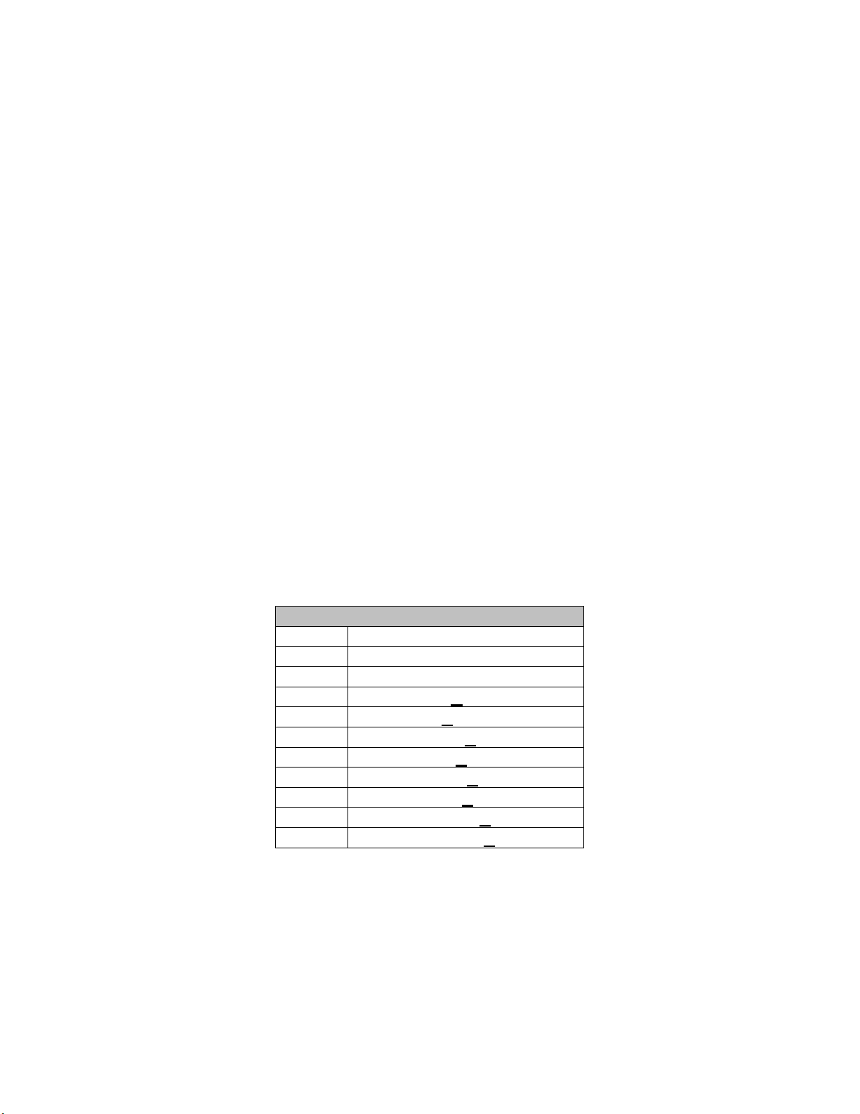
6 12/24 Hour Clock Format 0 = 12-hour / 1 = 24-hour
To configure the items above the display must be placed in configuration mode. To do this, start with
the timer’s POWER switch in the OFF position. Ensure that the handheld controller is properly
connected to the timer. To place the timer in configuration mode:
Turn the timer’s POWER switch to the appropriate ON position.
Press the “9” key within one second of turning the timer’s power on.
Press the “7” key press within one second of pressing the “9” key.
If the timer accepts the key sequence, the next-to-last digit will display a flashing “0” and the last digit
will display either a “1” (if the unit was last configured as a sports timer, as is the factory default) or a
“3” (if the unit was last configured as a time of day display).
If the timer displays anything other than a flashing “0” in the next-to-last digit, configuration mode
wasn’t properly initiated. Turn the timer off, wait ten seconds, and then try again.
Once in configuration mode, the flashing number shown in the next-to-last digit indicates the
parameter to be set (0-6) and the number shown in the last digit indicates the current value for that
parameter.
To change the value for the current parameter, use the number keys on the handheld
controller.
To scroll forward to the next parameter to be set, press the NEXT key.
To scroll backward to the previous parameter, press the PREV key.
NOTE: Once all parameters have been set, press and hold the NEXT key until the unit returns to
display mode.
Parameter 0: Timer Function
Press “1” to configure the unit as a period timer. A “1” will be displayed in the last digit. Set
parameters 1-5 then skip to “Timer Operation”.
- or-
Press “3” to configure the unit as a time of day display. A “3” will be displayed in the last digit. Set
parameter 1 to “5”, set parameter 2 to “4”, set parameter 3 to “5”, and set parameter 6 then skip to
“TIME OF DAY”
You can scroll forward and backward through the parameters to be set for the function you specified
by using the NEXT and PREVIOUS keys. If you configured the unit as a period timer, only
parameters 0-5 (those that must be set to use the unit as a period timer) will be available as you scroll
forward and backward through the parameters to be set. If you configured the unit as a time of day
display, only parameters 0 and 6 (the parameters that must be set to use the unit as a time of day
display) will be available as you scroll forward and backward through the parameters to be set.
Parameter 0 will always be available when in configuration mode so that the unit’s function can be
changed at any time.

Parameter 1: Number of Timer Digits
(Available when parameter 0 is set to “1” or “3”)
Use the number keys on the handheld controller to enter the desired number of timer digits. This
value may be from “1” to “10” but “5” is recommended since the timer has 5 digits. If this
parameter’s value is greater than “5” the timer will function properly, but not all of the clock digits will
be displayed. However, the timer will continue to count the underplayed time internally and the
displayed digits will still change accordingly.
Parameter 2: Number of Clock Digits
(Available when parameter 0 is set to “1” or “3”)
Use the number keys on the handheld controller to enter the desired number of clock digits. This
value may be from “1” to “10” but the timer will not accept a value greater than the number of timer
digits set in parameter 1 above.
For example, if you wish to use the unit as a sports timer (set in Parameter 0 above) and you want
the timer to display HH:MM (with no seconds, etc.) then you would set the number of clock digits to
four. The fifth display digit will no be used. Setting Parameter 2 allows the user to specify how many
of the timer digits (set in Parameter 1 above) will be used as clock digits.
Parameter 3: First Clock Digit Value
(Available when parameter 0 is set to “1” or “3”)
Possible values for this parameter are shown in the table below:
All other clock digits are sequential from the First Clock Digit Value. Therefore, if you set the number
of clock digits to “3” (set in parameter 2) and the First Clock Digit Value to “4” (set in parameter 3) the
clock will display H:MM, such as 9:30 (9 hours, 30 minutes).
Examples:
If you set the number of clock digits to “4” and want the timer to display HH:MM, set the First
Clock Digit Value to “3.”
First Clock Digit Value Settings
Setting Description
1 Days 10’s (XX:XX:XX:XX.XX)
2 Day’s 1’s (X:XX:XX:XX.XX)
3 Hours 10’s ( XX:XX:XX.XX )
4 Hours 1’s ( X:XX:XX.XX )
5 Minutes 10’s ( XX:XX.XX )
6 Minutes 1’s ( X:XX.XX )
7 Seconds 10’s (XX.XX )
8 Seconds 1’s ( X.XX )
9 1/10th Second ( .XX )
10 1/100th Second ( X)

If you set the number of clock digits to “3” and want the timer to display M:SS, set the First
Clock Digit Value to “6.”
If you set the number of clock digits to “2” and want the timer to display SS, set the First Clock
Digit Value to “7.”
Parameter 4: Horn Length
(Available only when parameter 0 is set to “1”)
Use the number keys on the handheld controller to specify how long the horn will sound, in seconds.
Parameter 5: Count Up / Count Down
(Available only when parameter 0 is set to “1”)
Press the “1” key to make the timer count up from zero to the user-programmed stopping time, if
programmed. If no user-preset stopping time is entered when the timer is in count up mode, the timer
will count up indefinitely. Press the “0” key to make the timer count down from the user-programmed
starting time to zero.
Parameter 6: 12-hour/24-hour Clock Format
(Available only when parameter 0 is set to “3”)
Press “0” to configure the display to show the time of day in a 12-hour clock format. Press “1” to
configure the display to show the time of day in a 24-hour clock format.
NOTE: Once all parameters have been set, press and hold the NEXT key until the unit returns to
display mode. TIMER OPERATION
When the unit is configured to count up a user-preset stopping time may be entered, but is optional.
If a user-preset stopping time is entered and the timer is started the timer will begin counting up from
zero and stop at the user-preset stopping time. If a user-preset stopping time isn’t entered and the
timer is started the timer will begin counting up from zero and will count up indefinitely until it is stopped.
When the unit is configured to count down a user-preset starting time must be entered. Once a user-
preset starting time is entered and the timer is started, the timer will begin counting down from the
user-preset time to zero.
User-preset stopping times (for count up mode) and user-preset starting time (for count down mode)
are entered using the same procedure.
To enter user-preset starting/stopping times:
1. Press and hold the SET CLOCK key until the display clears.
2. Using the numeric keypad, enter the desired starting/stopping time.
3. Press the NEXT key followed by the NEW GAME key to set the new time.

NOTE: Failing to perform step 3 will cause the board not to display the correct time.
Examples:
If Parameter 2 was set to 5 (5 clock digits) and Parameter 5 was set to 1 (count down)
and the desired starting time is 1:30:00 (one hour, 30 minutes), the starting time would be
entered by pressing 1 – 3 – 0 – 0 – 0. If the desired starting time is 45:00 (45 minutes), the
starting time would be entered by pressing 0 – 4 – 5 – 0 – 0.
If Parameter 2 was set to 4 (4 clock digits) and Parameter 5 was set to 0 (count up) and
the desired stopping time is 15:00 (15 minutes), the stopping time would be entered by
pressing 1 – 5 – 0 – 0. If the desired stopping time is 8:30 (8 minutes, 30 seconds), the
stopping time would be entered by pressing 0 – 8 – 3 – 0.
NOTE: As shown in the examples above, when entering starting/stopping times, all digits
specified in Parameter 2 must be used, sometimes making it necessary to use leading
zeros in order to take up the “unused” digits.
To start/stop the timer:
Press the START/STOP CLOCK key.
NOTE: Restarting a stopped timing sequence continues counting from the point at which it was
stopped. It does not reset the timer and begin counting over.
To reset the time:
stop the clock by pressing the START/STOP CLOCK key
Press and hold the NEW GAME key until the display clears and resets.
TIME OF DAY OPERATION
If the unit was configured as a time of day display the following parameters must also be set to the
specified value before the timer can be used as a time of day display:
Parameter 1 must be set to “5”
Parameter 2 must be set to “4”
Parameter 3 must be set to “5”
Parameter 6 can be set to either “0” or “1”
To set the time of day:
1. Press and hold the SET CLOCK key until the display clears.

2. Use the number keys on the handheld controller to enter the time of day in either a 12-hour
or 24-hour clock format, depending on the value you set for parameter 6 in configuration
mode.
3. Press the NEXT key to save the entered time and start the clock.
Table of contents