Sportig E30 User manual

1
Owner’s Manual
Retain this owner’s manual for future reference
Read and follow all instructions in this owner’s manual
Version A
1

Thank you
Thanks for purchasing this product.The product will help you exercise your muscles in
the correct way and to improve your fitness – and all this in a familiar environment.
Precautions
WARNING: This elliptical trainer has been designed and constructed to provide maximum
safety. Nevertheless, certain precautions should be taken when using exercise equipment.
Read the whole manual before assembling and using the elliptical trainer. The following
safety precautions should also be observed:
◆It is the responsibility of the owner to ensure that all users of the elliptical trainer are
adequately informed of all precautions. Use the elliptical trainers only as described
in this manual.
◆Keep children and pets away from this equipment at all times. DO NOT leave them
unsupervised in the room where this elliptical trainer is kept.
◆Please make sure that the elliptical trainer has been assembled properly and all the
screws are locked .
◆Place the elliptical trainer on a level surface, with at least 1.0 m of clearance on each
side of elliptical trainer. To protect the floor or carpet from damage, please place a
mat under the elliptical trainer.
◆Keep the elliptical trainer indoors,without moisture and dust.Maintain the using
place ventilation. Do not use it in the airless place.
◆Don’t put any sharp things around the elliptical trainer.
◆Wear proper clothes while exercising; do not wear loose clothes that could be
tripped on the elliptical trainer.Always wear athletic shoes for foot protection while
exercising.
◆Do not use this product if you are over 150kg.Please choose our other series of
elliptical trainers.
◆Do not put your hands on the moving parts to prevent injures.
◆Keep your pedaling speed in control.
◆If you find your elliptical trainer works not normal, do not use it immediately.
◆No more than one person should use the elliptical trainer at the same time.
◆If you feel pain or dizziness while exercising, stop exercising and askfor adoctor.
2

Safety notice
When you are remedial or have below symptoms, after discussing with your doctor, then
could use this elliptical trainer.
1. Waist paining now and leg, waist, neck hurt before, legs, waist, neck and hand numbly
please do not use.
2. Have anamorphic arthritis, rheumatic and gout.
3. Have osteoporosis and other abnormality.
4. Have perfunctory system obstacle (heart disease, blood obstacle, hypertension).
5. Have breathobstacle.
6. Using the manpower pulse adjust machine or insert into the bodymachine.
7. Havesarcomata.
8. Have thrombus or othersymptoms.
9. Have diabetes or be caused by diabetes feelingobstacle.
10. Have skintrauma.
11. Hyperpyrexia caused by sick(38 ℃or over 38 ℃).
12. Abnormal back bone or back bonebending.
13. Pregnant orcatamenia.
14. Feel physical abnormality, need convalesce.
15. Body condition is not verywell.
16. The aim is tohealing.
17. Except the upper symptoms, feel other physical abnormality.
----Maybe cause the accident or the poor body condition.
Before beginning any exercise program, please consult your physician. This is especially
important for person who are over thirty five years old ,pregnant or with no experience of
excersice or have any health problem.To reduce the risk of serious injury, read all above
important precautions and instructions in this manual and all warnings on your elliptical
trainer before using.
3

Technical information:
PRODUCT NO. E30
DIMENSION Unfold:1660×720×1580mm
MAX LOAD 150KG
SPEED RATIO 10.3
FLYWHEEL Double magnetic way,Φ280/9kg
RESISTANCE 1-32
STRIDE LENGTH 420×200
*WE RESERVE THE RIGHT TO AMEND THE PRODUCT WITHOUT PRIOR NOTICE.
3URGXFWLQVWUXFWLRQ
+DQGOHEDU
&RQVROH
+DQGOHSXOVH
%RWWOHKROGHU
0DLQIUDPH
8SSHUXSULJKWSRVW
:KHHO
)URQWVWDELOL]HU
3HGDO
5HDUVWDELOL]HU
4

Screw bag list
NO. NAME SPECIFICATION QTY
26 Allen C.K.S. half thread screw M10×70×20 4
28 Flat washer Φ10 4
31 Flat washer Φ8.5×Φ20×t1.5 4
34 Philips pan head full thread screw M4×10 16
36 Flat washer Φ62
38 Philips C.K.S. self-tapping screw ST4×16 2
101 Philips C.K.S. self-tapping screw ST4×12 4
L shape wrench 5×40×100 1
33 M4×16-2
34 M4×10-16
38 ST4×16-2
37 M6× 15-2
35 Φ 10×45× M6×20-2
26 M10×70×20-4
27 Φ10-4 28 Φ10-4
36 Φ6-2 31 Φ8.5*F20*t1.5-4
L5S-A
L5-B
L6
29 M8*20-4
101 ST4×12-4
E30
103 Φ17-2
5

L shape wrench 6×66×140 1
NO. NAME SPECIFICATION QTY
27 Spring washer Φ10 4
29 Allen pan head full thread screw M8×20 4
33 Philips pan head full thread screw M4×16 2
35 Allen C.K.S. hollow screw Φ10×45×M6×20 2
37 Allen C.K.S. full thread screw M6×15 2
103 Curve elastic washer Φ17 2
L shape wrench 5×80×80S(with philips)
6

ASSEMBLY INSTRUCTIONS
Step 1:
1. Attach the front stabilizer (2) to the main frame (1) with curved washer(28), spring
washer(27) and Allen C.K.S. half thread screw(26).
Step 2:
1. Attach the rear stabilizer (3) to the main frame (1) with curved washer(28), spring
washer(27) and Allen C.K.S. half thread screw(26)
7

Step 3:
1. Connect motor communication wire(11) and upright post communication wire(12).
2. Attach upper upright post(4) to the main frame(1). Lock Allen flat head set-bolt (39)
preinstalled on the main frame, to fixed upright post. after that,cover back the Hole
Plug(102).
Attention: the two screws of the upright post should be locked in turn until the riser is firmly
locked. When finished tightening one screw, then start on the other screw in turn until
tightened the upright post.
8

Step 4:
1. Assemble of Body arm L/R, First, lubricate both ends of the axis,set the curve washer
(103) to the both side of the Axle (25). Then assemble Bodyarm-L(5) to the left of
Axle(25). Bodyarm-R(6) to the right of Axle(25). Lock with flat washer(31) and Allen
C.K.S. full thread screw(29).
2. Assemble Body arm cover (17) and Body arm cover (16) to the Body arm-left(5) with
Phillips pan head full thread screw(34).
3. Same as above way to assemble Body arm cover (17) and Body arm cover (16) to
the Body arm-right(6)
Coated lubricate
oil
Coated lubricate
oil
9
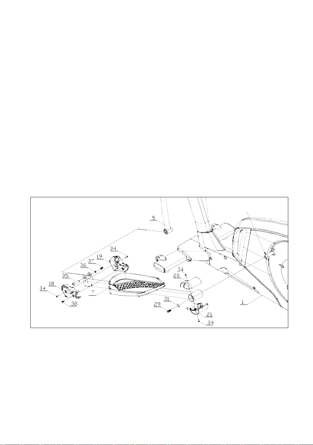
Step 5:
1.First, lubricate both ends of the axis, then Attach the axle sleeve of left rear pedal
supporter (7) to the axle of main frame(1) with Flat washer (31) and Allen C.K.S. half
thread screw (29).
2.Attach the axle sleeve of left front pedal supporter(7)to left body arm(5)with Allen
C.K.S. hollow screw(35), flat washer(36) and Allen C.K.S. full thread screw(37).
3.Attach the rear cover of pedal supporter(20/21) to left pedal supporter(7) with Philips
pan head full thread screw(34). Attach the front cover of pedal supporter(18/19) to left
pedal supporter(7) with Philips pan head full thread screw(3 and Philips C.K.S. self-
tappingscrew(38).
4. Install the Pedal supporter(R) (8)with same way.
Coated lubricate oil
10
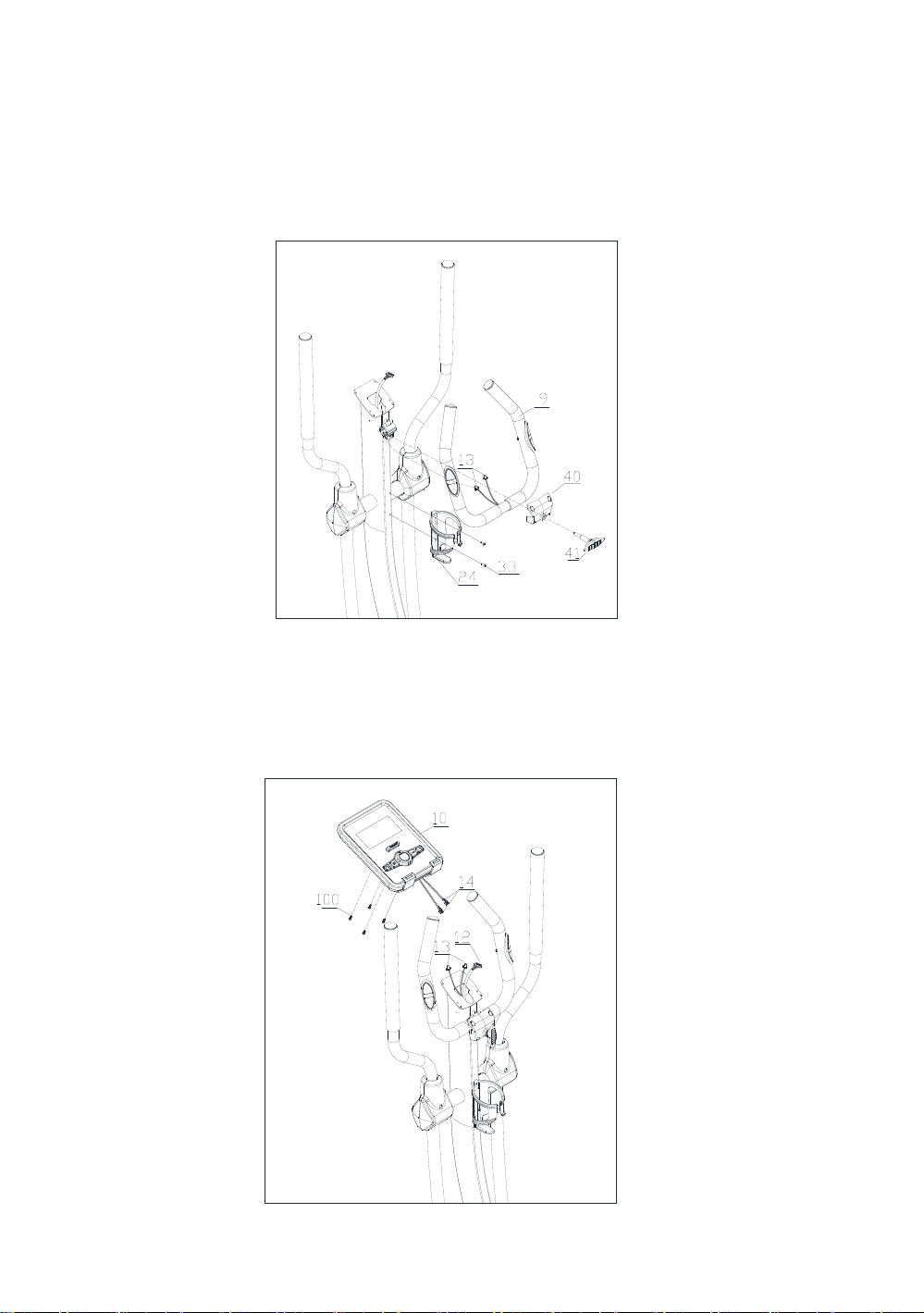
Step 6:
1. Fixed the handlebar (9). Through handle pulse connection wire(13) out of the upper
upright post(4). Then through T shape knob (41) out of the handlebar front cover (40).
Rotate inside. Notice: T shape don’t rotate tightly firstly.
2. Attach bottle holder(24) to upper upright post(4) with Philips pan head full thread
screw(33).
Step 7:
1.Connect console communication wire(12) with the interface of back console. Connect
handle pulse communication wire (13) with console outset(14).
2.Attach console(10) to upper upright post(4) with Philips C.K.S. full thread screw(100).
11

Step 8:
1. Attach handlebar cover –left (22) and right (23) to upper upright post (4) with Phillips
pan head full thread screw(34).
2. Lock the handlebar front cover (40) with Phillips C.K.S. self-tapping screw(101).
3. Adjust the Pulse tube to the suitable position. Rotate T shape knob.
Step 9:
1. Insert the power pugs into power hole as shown below. Assembling finished
12
Half-drawing for assembly
4
12
25
31
29
17 34
16
34
29
31
16
34
34
9
13
100
10
14
35
36
37
18
34
19
38
34
20
31
21
29
34
37
36
35
19
18
34
34
38
34
21
34
20
31
29
8
21
3
5
6
12
11
17
34
7
33
24
34
22
34
23
28
27
26
28
27
26
28
27
26
28
27
26
101
40
41
39
103
103
102
13

Part List
NO. NAME SPECIFICATION QTY
1
Main frame 0.74 ㎡
1
2
Front stabilizer PT50×100×t1.5×600
1
3
Rear stabilizer PT50×100×t1.5×700
1
4
Upper Upright post 0.27 ㎡
1
5
Body arm(L) 0.161
1
6
Body arm(R) 0.161
1
7
Pedal supporter(L) 0.2 ㎡
1
8
Pedal supporter(R) 0.2 ㎡
1
9
Handlebars 0.085 ㎡
1
10 Console 5.5 " LCD/English
1
11 Motor communication wire L-550mm
1
12 Console communication wire L-1100mm
1
13 Handle pulse connection wire L-650mm
2
14 Console outset
2
16 Body arm cover 160.8×103×56
2
17 Body arm cover 160.8×103×45
2
18 Front pedal supporter cover 1 125.1×36.7×89.4
2
19 Front pedal supporter cover 2 125.1×39.7×89.4
2
20 Rear pedal supporter cover 1 107.7×103×34.5
2
21 Rear pedal supporter cover 2 107.7×103×37.5
2
22 Handlebar cover(L) 176.5×53.2×117.5
1
23 Handlebar cover(R) 176.5×53.2×117.5
1
24 Bottle holder Φ93×150
1
25 Axle Φ17×339.5
1
26 Allen C.K.S. half thread screw M10×70×20
4
27 Spring washer Φ10
4
28 Flat washer Φ10
4
29 Allen C.K.S. Full thread screw M8×20 4
31 Flat washer Φ8.5×Φ20×t1.5
4
33 Philips pan head full thread screw M4×16 2
34 Philips pan head full thread screw M4×10
16
35 Allen C.K.S. hollow screw Φ10×45×M6×20
2
14

36 Flat washer Φ6
2
37 Allen C.K.S. full thread screw M6×15
2
38 Philips C.K.S. self-tapping screw ST4×16 2
39 Allen flat head set-bolt M12×60
2
40 Handlebar front cover 89×73.5×35
1
41 T shape knob M8×30
1
100 Phillips C.K.S. full thread screw M5×10
4
101 Philips C.K.S. Self-tapping screw ST4×12
4
102 Hole Plug Φ15
2
103 Curve washer Φ17
2
15

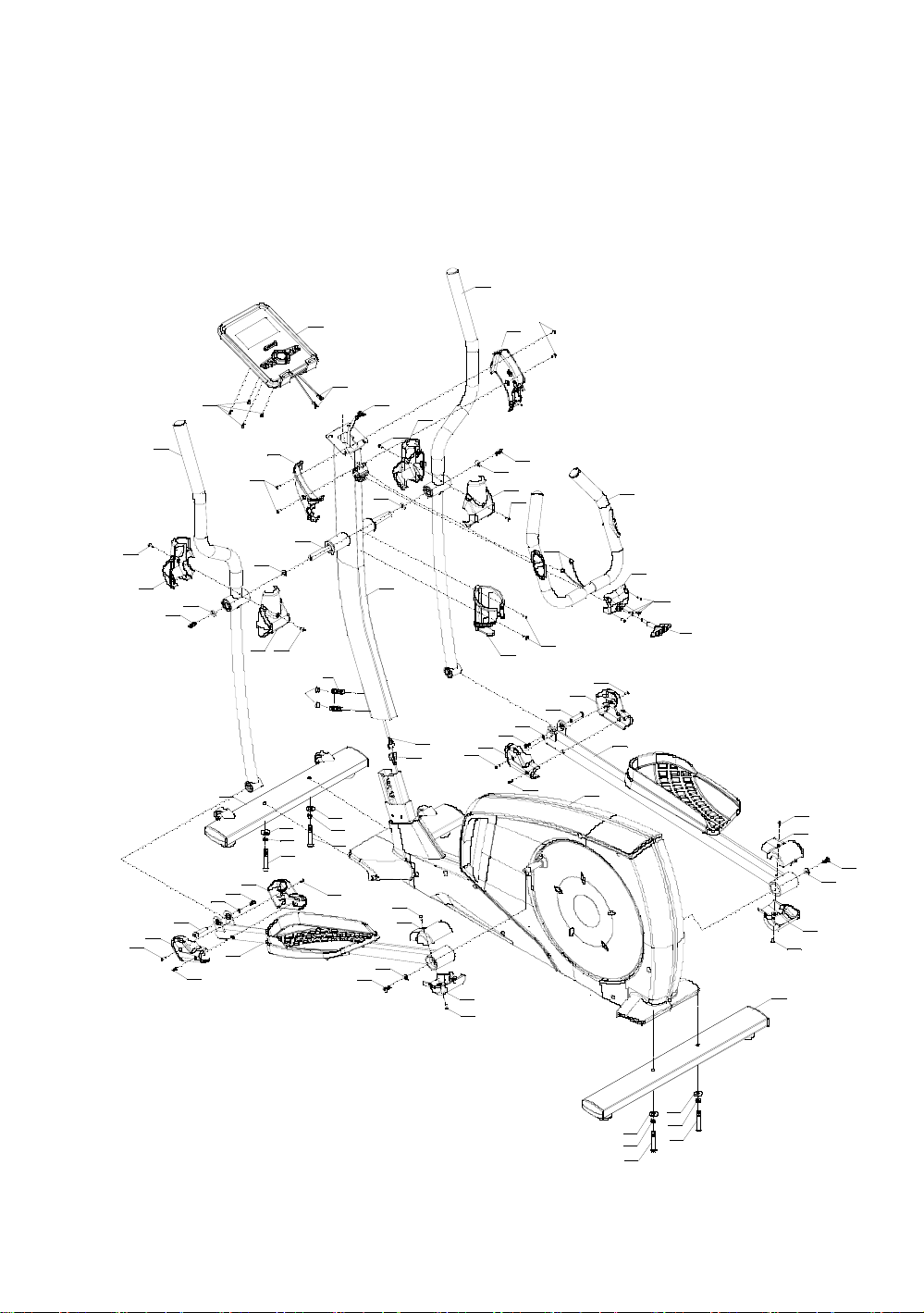
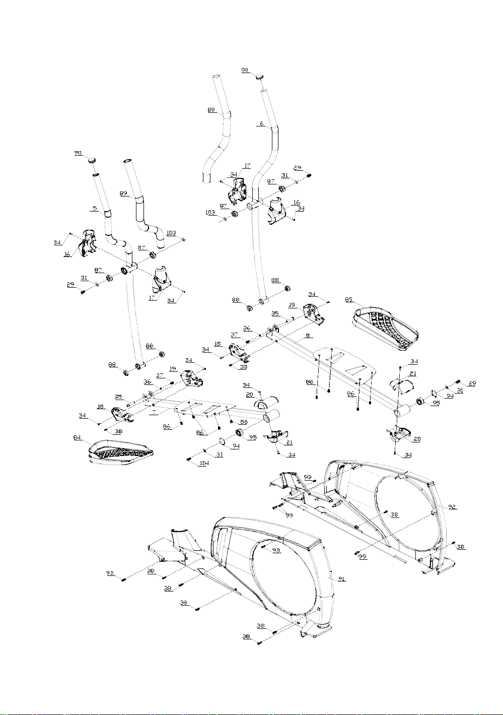
Drawing for assembly
16
17

Part list
NO. NAME SPECIFICATION QTY
1
Main frame 0.74m2
1
2
Front stabilizer PT50×100×t1.5×600
1
3
Rear stabilizer PT50×100×t1.5×700
1
4
Upper Upright post 0.27m2
1
5
Body arm(L) 0.161m2
1
6
Body arm(R) 0.161m2
1
7
Pedal supporter(L) 0.2m2
1
8
Pedal supporter(R) 0.2m2
1
9
Handlebars 0.085m2
1
10 Console 5.5 " LCD/English
1
11 Motor communication wire L-550mm
1
12 Console communication wire L-1100mm
1
13 Handle pulse connection wire L-650mm
2
14 Console outset
2
15 Power adapter 240V
1
16 Body arm cover 160.8×103×56
2
17 Body arm cover 160.8×103×45
2
18 Front pedal supporter cover 1 125.1×36.7×89.4
2
19 Front pedal supporter cover 2 125.1×39.7×89.4
2
20 Rear pedal supporter cover 1 107.7×103×34.5
2
21 Rear pedal supporter cover 2 107.7×103×37.5
2
22 Handlebar cover(L) 176.5×53.2×117.5
1
23 Handlebar cover(R) 176.5×53.2×117.5
1
24 Bottle holder Φ93×150
1
25 Axis Φ17×339.5
1
26 Allen C.K.S. half thread screw M10×70×20
4
27 Spring washer Φ10
4
28 Flat washer Φ10
4
29 Allen C.K.S. Full thread screw M8×20 9
30 Spring washer Φ8
4
18

31 Flat washer Φ8.5×Φ20×t1.5
6
32 Hex self-locking nut M10
3
33 Philips pan head full thread screw M4×16 2
34 Philips pan head full thread screw M4×10
16
35 Allen C.K.S. hollow screw Φ10×45×M6×20
2
36 Flat washer Φ6
2
37 Allen C.K.S. full thread screw M6×15
6
38 Philips C.K.S. self-tapping screw ST4×16 17
39 Allen flat head set-bolt M12×60
2
40 Handlebar front cover 89×73.5×35
1
41 T shape knob M8×30
1
42 Turntable Φ466.6×24.1
2
43 Turntable rubber buckle Φ12.4×13 12
44 Phillips C.K.S. Tail cutting self-tapping screw ST4×10 12
45 Crank square iron
2
46 Hex half thread screw M10×55×20
2
47 Hex full thread screw M4×20
2
48 Flat key 5×5×15
2
49 Allen countersunk head full thread screw M6×15
2
50 Flat washer Φ8×Φ30×t3.0
2
51 Fixed idler wheel
1
52 Idler adjustment connecting shaft Φ15×30
1
53 Hex nut M8
2
54 Hex locking nut M8
7
55 Idler wheel Φ38×22
1
56 Circlip for shaft Φ10
1
57 End cap 45×90×t1.5
4
58 Feet pad Φ49×22×M10×26
4
59 Wheel Φ54.5×23.5
2
60 Allen C.K.S. hollow screw Φ8×33×M6×15
2
61 Hex full thread screw M5×60
1
62 Hex nut M5
2
63 Deep groove ball bearing 6004-2RS
2
19

64 Fixed magnetic induction
1
65 Philips washer head end-cutting self-tapping screw ST4×12
1
66 Crank axle sleeve 1 Φ25×Φ20.1×4.6
1
67 Crank axle sleeve 3 Φ40×Φ20.1×7.7
1
68 Crank axle Φ20×115
1
69 Belt pulley Φ308×22
1
70 Crank axle sleeve 2 Φ25×Φ20.1×10.2
1
71 Fixed magnet set
1
72 Magnetic control fixed axle Φ12×50
1
73 Brake tension spring Φ11.5×Φ1.2×13
1
74 Magnet motor
1
75 Double flywheel Φ280/9KG
1
76 Motor belt 540PJ6
1
77 Brake line
1
78 Rail plastic cap Φ42.5×30
2
79 Handle pulse
2
80 Philips C.K.S. self-tapping screw ST4×20
2
81 Pipe plug Φ28×t1.5
2
82 Foam grip Φ32×t3.0×480
2
83 Circlip for shaft Φ12
2
84 Pedal(L) 406×187×74
1
85 Pedal(R) 406×187×74
1
86 Allen C.K.S. full thread screw M6×12
8
87 Deep groove ball bearing 6003-2RS
4
88 Deep groove ball bearing 6200-2RS
4
89 Foam grip Φ36×t3.0×720
2
90 Pipe plug Φ32×t1.5
2
91 Motor cover(L) 1291.1×72×616.2
1
92 Motor cover(R) 1291.1×75.9×616.2
1
93 Philips C.K.S. Self-tapping screw ST4×25
2
94 Circlip for holes Φ40
2
95 Self-aligning ball bearing 2203-2RS
2
96 Hex full thread screw M8×120
1
97 Power communication wire
1
20
Table of contents
Other Sportig Exercise Bike manuals


Popular Exercise Bike manuals by other brands


Sunny Health & Fitness
Sunny Health & Fitness SF-B121021 user manual

Monark
Monark 827E instruction manual

Stamina
Stamina 1310 owner's manual

American Fitness
American Fitness SPR-BK1072A owner's manual
 Service manual")
Cateye
Cateye CS-1000 (CYCLO SIMULATOR) Service manual

BH FITNESS
BH FITNESS H9158H Instructions for assembly and use