Spread-a-Bale M Series Manual

M Series July 2020
Mini Mini RB1.8 Midi Maxi
From Serial Number: SAB200
SAFETY FIRST!
Most accidents that involve product operation, maintenance and repair are caused by failure
to observe basic safety rules or precautions. An accident can often be avoided by
recognising potentially hazardous situations before an accident occurs. A person must be
alert to potential hazards. This person should also have the necessary training, skills and
tools to perform these functions properly.

Improper operation, lubrication, maintenance or repair of this product can be
dangerous and could result in injury or death.
Do not operate or perform any lubrication, maintenance or repair on this product, until
you have read and understood the operation, lubrication and maintenance or repair
information.
Safety precautions and warnings are provided in this manual and on the product. If these
hazard warnings are not heeded, bodily injury or death could occur to you or to other
persons.
The hazards are identified by the “Safety Alert Symbol” and followed by a “Signal Word”
such as “Danger”, “Warning “or “Caution”. The safety Alert “Warning” label is shown below.
Warning
The meaning of this safety alert symbol is as follows:
Attention! Become Alert! Your safety is involved.
The message that appears under the warning explains the hazard and can be either written
or pictorially presented.
Operations that may cause product damage are identified by “NOTICE” labels on the
product and in this publication.
Spread-a-Bale cannot anticipate every possible circumstance that might involve a
potential hazard. The warnings in this publication and on the product are, therefore,
not all inclusive. If a tool, procedure, work method or operating technique that is not
specifically recommended by Spread-a-Bale is used, you must satisfy yourself that it
is safe for you and others. You should also ensure that the product will not be
damaged or made unsafe by the operations, lubrication, and maintenance or repair
procedure that you choose.
The information, specifications and illustrations in this publication are on the basis of
information that was available at the time that the publication was written. The specification,
torques, pressures, measurements, adjustments, illustrations and other items can change at
any time. These changes can affect the service that is given to the product. Obtain the
complete and most current information before you start any job. Spread-a-Bale dealers have
the most current information available.
EC Declaration of Conformity
In accordance with ED Directive 2006/42/EC
1. We, Spread-a-Bale Ltd declare under our responsibility that the product
2. Machine Name: SPREAD-A-BALE
3. Machine Type: M Series, Mini, Mini RB1.8, Midi & Maxi

4. Which this certificate conforms to the essential Health and safety requirements of
EEC Directive 2006/42/EC & 2004/108/EC
5. To effect correct application of the essential Health and Safety requirements
stated in the EEC Directives, the following standards were consulted:
BS EN ISO 12100-1
BS EN ISO 12100-2
BS EN ISO 13857:2008
BS EN 703:2004 + A1:2009
6. Name: Michael Hughes
7. Position: Managing Director
8. Address:
Spread-a-Bale Limited
Rosscliffe Road
Rossmore Industrial Estate
Ellesmere Port
CH65 3AS

______Machine Identification
Machine Identification
Enter the relevant data in the following list upon
acceptance of the machine:
Serial Number
Machine Model
Year of Construction
Delivery Date
First Operation
Accessories
Operating Instructions: July 2020
Dealer Address: Name: ...................................................................
Street: ...................................................................
Place: ...................................................................
Tel.: ................................................................. ....
Spread-a-Bale Address: Spread-a-Bale Limited
Rosscliffe Road
Rossmore Industrial Estate
Ellesmere Port
CH65 3AS
Tel.: +44 (0) 1244 394258
E-Mail: [email protected]

_______Table of Contents
Contents
Machine Identification .............................................................................. 5
Contents …............................................................................................... 6
Introduction .............................................................................................. 8
Foreword................................................................................................... 8
Warranty Guidelines................................................................................ 8
1.0 Safety Data......................................................................................... 9
1.1 Safety Symbols................................................................................... 9
1.2 Use for the Intended Purpose............................................................. 10
1.3 Operational Safety.............................................................................. 10
1.4 No Liability for Consequential Damage ............................................. 11
1.5 Accident Prevention............................................................................ 11
1.6 Changing Equipment.......................................................................... 11
1.7 Servicing & Maintenance.................................................................... 11
1.8 Operating Areas................................................................................ 12
1.9 Authorised Operators......................................................................... 12
1.10 Protective Equipment ...................................................................... 12
1.11 Preparing for Work........................................................................... 12
1.12 Starting Work................................................................................... 12
1.13 Working Safely................................................................................. 13
2.0 Installation........................................................................................ 14
2.1 Attachment ........................................................................................ 14
3.0 Technical Data Spread-A-Bale........................................................ 15
4.0 Adjustment/Operation .................................................................... 16
4.1 Description......................................................................................... 16
4.2 Control............................................................................................... 17
4.3 First Operation.................................................................................... 17
4.4 Loading Bale Mode............................................................................. 17
4.5 Spreading................................................................................... 17
4.6 Loading a Bale................................................................................... 17
4.7 Removing the Bale Twine or String ................................................... 18
4.8 Spreading .......................................................................................... 18
4.9 Moving and Handling the Spread-A-Bale .......................................... 19
4.10 Detachment...................................................................................... 19
4.11 Control Adjustments.......................................................................... 19
4.12 Checks ............................................................................................. 20

_______Table of Contents
5.0 Servicing and Maintenance ............................................................. 21
5.1 Servicing ............................................................................................. 21
5.2 Cleaning ............................................................................................. 21
5.3 Lifting Attachment .............................................................................. 21
5.4 Preparing for Storage ........................................................................ 22
5.5 Greasing the Bearings........................................................................ 22
5.6 Hydraulic Hose Inspection………………………………………………. 22
5.7 Changing a Hydraulic Hose................................................................ 22
5.8 Changing a Control Unit ..................................................................... 22
5.9 Changing a Belt................................................................................... 22
5.10 Changing a Belt Bearing.................................................................... 23
5.11 Changing a Belt Motor ..................................................................... 23
5.12 Changing a Rotor Motor ................................................................... 24
5.13 Changing a Rotor Bearing ................................................................ 24
5.14 Operator Support .............................................................................. 24
5.15 Maintenance Intervals....................................................................... 24
5.16 Overview of Lubricating Points ......................................................... 25
5.17 Lubricating the Machine ................................................................... 25
5.18 Handling of Lubricants ..................................................................... 25
5.19 Hydraulic Oil Specification…………………………………………… 26
5.20 Grease Specification…………………………………………………… 26
6.0 Faults and Remedies......................................................................... 27
7.0 Parts and assembly.......................................................................... 29

___________________1. Safety Data
Introduction
Foreword
This manual has been written to provide the
owner and user with clear instructions on
the operation and maintenance of the
Spread-A-Bale unit.
By following the instructions in the manual
you will not only get many years of service
from your Spread-A-Bale, but you will
make your work much easier.
If any part of this manual is not clear, then
please contact your dealer or the
manufacturer for explanations. It is very
important that you understand and comply
with these instructions.
Use only genuine authorised parts when
replacements are required, you are
strongly advised to purchase any spare
parts from an exclusive dealer, no
purchases from the manufacturer.
The variety of conditions and vehicles that
this unit can be operated with means that
Spread-a-Bale cannot provide up to date
information on the performance and
efficiency of the units it manufactures. The
company therefore accepts no
responsibility for loss or damage caused
by its publications or any error or omission
therein. Should the unit be used in
particularly adverse conditions contact
your local dealer for specific instructions.
Together with the Operating Instructions,
you receive a Spare Parts List and a
Machine Registration form. Field service
technicians will instruct you in the
operation and servicing of your machine.
Following this, the Machine Registration
form is to be returned to Spread-a-Bale.
This confirms your formal acceptance of
the machine. The warranty period begins
on the date of installation.
We reserve the right to alter
illustrations as well as technical
data and weights contained in
these Operating Instructions for
the purpose of improving the
Spread-A-Bale.
Warranty Guidelines
1. The period of liability for material
defects (warranty) relating to our
products is 12 months. In the case of
written deviations from the statutory
provisions, these agreements shall
apply.
They shall become effective upon
installation of the machine with the end
customer. All wear parts are excluded
from the warranty.
See additional information in Sections
1.2 and 1.13
2. Warranty claims must be submitted to
Spread-a-Bale via your dealer. It is only
possible to process claims which have
been correctly completed and submitted
via an authorised Spread-a-Bale dealer
repair.
3. Claims for fitting non original parts will
not be considered unless prior
agreement has been obtained.
4. The repairer must be advised that the
work it to be the subject of a warranty
claim beforehand
5. The damaged parts must be retained
for inspection and returned carriage paid
if required.
The right to withdraw warranty is
reserved if:
a) Non-original parts fitted
b) The machine has been abused,
badly maintained or used for
purposes other that for which is was
designed.
___________________1. Safety Data
1. Safety Data
The following warnings and safety
Instructions apply to all sections of these
Operating Instructions.
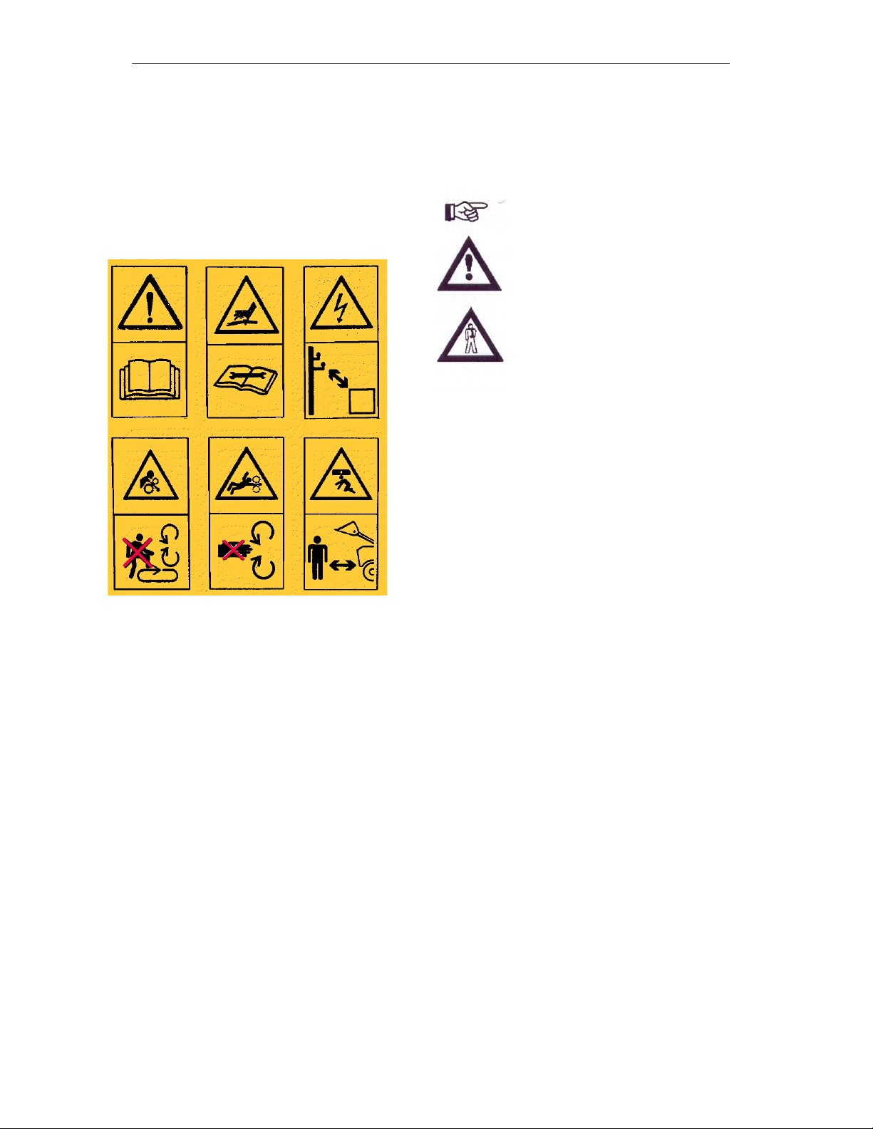
1.1 Safety Symbols
On the machine
On all hydraulic hose for operating
conditions, check outer hose cover for: no
cracks; bubbles; deformation; wear or
kinking, no distress on intersection
between hose and end fitting and no fluid
weeping and leaking.
Operating Instructions:
The Operating Instructions distinguish
between three different types of warning
and safety instructions. The following
graphic symbols are used:
Important!
Risk of injury!
Risk of fatal and serious
injuries!
It is important that all the safety
instructions contained in these Operating
Instructions and all the warning signs on
the machine are read carefully.
Ensure that the warning signs are legible.
Replace any signs that are missing or
damaged.
These instructions must be followed in
order to prevent accidents. Inform other
users of the warnings and safety
instructions.
Do not carry out any operations which
may affect safe use of the machine.
Leave all panels and guards in place, if
any are removed to make repairs they
must be replaced prior to operating the
unit. Carry out any repair or maintenance
activities with the unit isolated from any
hydraulic power and the unit securely
supported to prevent any inadvertent
movement or damage.

___________________1. Safety Data
1.2 Use for the Intended
Purpose
The Spread-A-Bale is built using the latest
technology and in accordance with the
relevant recognised safety regulations.
However, risks of injury for the operator or
third parties and impairment of the
machine or other tangible assets can arise
during use.
The machine is only to be operated when
in a technically perfect condition and for
the intended purpose, taking into
consideration safety and risks and
following the Operating Instructions. In
particular, faults that can impair safety
should render the machine out of
serviceable action until the faults are
remedied.
Original parts and accessories have been
specially designed for this machine. Spare
parts and accessories not supplied by us
have not been tested or authorised.
Installation or use of non-original products
may have a detrimental effect on specific
design features of the machine and affect
the safety of machine operators and the
machine itself. Spread-a-Bale will accept
no liability for damage resulting from the
use of non-original parts or accessories.
Spread-a-Bale will accept no liability for
damage resulting from improper use such
as blade/rotor debris damage or
contamination to the hydraulic system due
to poor connection hygiene and dirt
ingress. The risk will be borne solely by
the operator.
1.3 Operational Safety
For safe operation only fully qualified and
authorised operators are to use this
equipment. To qualify as an operator, you
must understand the instructions in this
manual, be able to assess the suitability of
the loader you are going to use with the
unit, be licensed to drive the loader and
understand the relevant safety and work
regulations. The actual requirements may
vary depending on where you are and it is
important that you ensure that you meet
the local requirements regarding the use
of such equipment before using a Spread-
A-Bale unit.
Observe the following precautions:
DO NOT use Spread-A-Bale as an
access platform
DO NOT carry passengers whilst
operating Spread-A-Bale
DO NOT operate the equipment with
anyone in the danger zone
DO NOT modify any of the equipment
Operate the unit smoothly with no
sudden movements.
Hitch only to the designated points
Never alter or remove any part of the
equipment
Watch for overhead obstructions
Ensure that the rated load capacity of
the lifter used with the unit is not
exceeded
Keep others well clear of your work
area
Be careful of the welfare of the animals
in any areas where you are operating
Spread-A-Bale

___________________1. Safety Data
1.4 No Liability for
Consequential Damage
The Spread-A-Bale has been
manufactured with great care. However,
problems may still occur when it is used
for the intended purpose.
These may include:
• Worn wearing parts.
• Damage caused by external factors.
• Incorrect driving speeds.
• Incorrect setting of the unit (incorrect
attachment, non-adherence to the Setting
Instructions).
Therefore, it is crucial to always check
your machine before and during operation
for correct operation.
Compensation claims for damage which
has not occurred to the machine is
excluded. This includes any consequential
damage resulting from incorrect operation.
1.5 Accident Prevention
In addition to the Operating Instructions, it
is important to observe the accident
prevention regulations specified by
agricultural trade associations.
1.6 Changing Equipment
• Use suitable supports to secure any
raised frame sections suspended above
you!
• Caution! Risk of injury due to projecting
parts!
Never climb on to rotating parts
such as the rotor blades. These
parts may rotate causing you to
slip and suffer serious injury!
1.7 Servicing &
Maintenance
Ensure that regular checks and
inspections are always carried out within
the periods required by law or specified in
these Operating Instructions.
When maintaining the Spread-A-Bale unit
please observe the following.
1. Ensure that the unit is isolated from
any hydraulic power source.
2. The unit is securely supported on a
firm stable surface.
3. The rotor head is in the down position.
Prior to performing maintenance and
servicing work, ensure that the machine is
positioned on solid, level ground.
Before cleaning the machine with water,
steam jets (high-pressure cleaning
apparatus) or other cleaning agents, cover
all openings into which, for reasons of
safety or operation, no water, steam or
cleaning agents are to penetrate
(bearings, for instance).
Next, check all hydraulic lines for leaks,
loose connections, chafe marks and
damage. Remedy any deficiencies
immediately!
When carrying out servicing and
maintenance work, retighten any loose
bolts and hydraulic connections.

___________________1. Safety Data
1.8 Operating Areas
The operating areas include the belt,
hydraulic connections and rotors as well
as all other operating points requiring
maintenance.
All operating areas will be specified and
described in detail in the following
chapters on servicing and maintenance.
Observe all safety regulations included in
the Section dealing with Safety, and in the
subsequent sections.
1.9 Authorised Operators
Only those persons who have been
authorised and instructed by the operator
may operate the machine.
1.10 Protective Equipment
For operation and maintenance, it is
recommended that you wear:
Tight fitting clothing.
•Strong protective gloves (to
provide protection against sharp-
edged machine components).
Protective goggles (to stop dirt
getting into your eyes).and safety
boots
Ear Protection
1.11 Preparing for Work
Before starting the day’s work complete
the following with the Spread-A-Bale unit
isolated from any hydraulic power source
and securely supported. The head should
be in the lowered position:
1. Check for mechanical and hydraulic
pipe damage.
2. Check for any conveyor belt damage
and that the bed has sufficient tension to
operate.
3. The edge strip to the conveyors is in
position with no damage.
4. Blade bolt tightness to specific torque
setting of 85Nm
5. Lifting devices securely attached to
specific torque setting of 210Nm
6. Bearings are clear of debris and well-
greased.
7. Both sets of hydraulic connections to
drive vehicle are clean and dirt free prior
to connection.
If any problems are identified they should
be corrected before the unit is used.
Hydraulic fluids under pressure
can harm the skin and eyes and
cause serious injury or death.
1.12 Starting Work
Ensure that the area is clear and warn any
bystanders before powering up the unit.
Anybody in the vicinity should be warned
Before the unit is started, particular care
must be made to keep children well away
from the unit.
Connection and disconnection of the
hydraulics must be done with the unit on
the floor and the power unit of the tractor
or telescopic handler turned off and the
key removed.
If testing the unit, then ensure that all
items have been checked for tightness
and that no one is in the vicinity of the unit
when any of the equipment is being
tested.
Do not get out of the driver’s seat when
the unit is attached and the tractor or
telescopic handler is powered up.

___________________1. Safety Data
1.13 Working Safely
An unbalanced tractor or
telescopic handler could tip or
overturn causing serious injury.
Make sure that the safe lifting
limits are closely followed at all
times. Operating conditions e.g.
rough or sloping surfaces may
affect the load carrying capacity
considerably.
Ensure that the tractor or telescopic
handler is ready for the task to be done
with the Spread-A-Bale unit.
Follow safe practices:
Operate the controls such that the
tractor or telescopic handler is
manoeuvred smoothly.
Never get off when the unit is
operational.
When moving ensure that there is
sufficient room all round and that
visibility is good.
Ensure the Spread-a-Bale front
hood is down when moving.
Ensure that the ground is
sufficiently level to maintain
stability.
Before getting off the tractor or
telescopic handler lower the unit to
the ground, engages the parking
brake, switch off the engine and
remove the key.
Be careful of other people
and never let any untrained
or unskilled operator use the
equipment.
When working never let anyone
pass or stand under a raised
Spread-A-Bale unit.
Never lift the unit unless it is
securely fixed using the lifting
attachments.
When using the unit avoid sudden
starts, stops and changes of
direction. Let all moving parts stop
before reversing oil flow.
Keep the unit as close as possible
to the ground when transporting.
Ensure that there are no overhead
obstructions when operating the
unit.
Never attempt to unplug
the hydraulic connections
or adjust anything with the
engine running. To do so
could result in serious
injury or death.

___________________1. Safety Data
2.0 Installation
When carrying out installation and
maintenance work there is a higher risk of
injury. It is important that you familiarise
yourself with the machine and read the
Operating Instructions beforehand.
Operator instruction and initial installation
of the machine are carried out by our
service technicians or authorised
distributors.
The machine must not be used in any way
beforehand! The machine can only be
released for operation after instructions
have been provided by our service
technicians or authorised distributors.
• If any modules or parts have been
removed for transportation, these shall be
mounted by our service technicians/
authorised dealers before the instruction
takes place.
• Check all important screw connections!
• Lubricate all nipples and joints!
• Check all hydraulic connections and lines
for damage.
2.1 Attachment
The unit is attached to the loader by the
lifting eyes at the end nearest the
hydraulic controller.
Position the Loader facing the rear of the
Spread-A-Bale and by a combination of
driving forward and using the boom
controls attach the Spread-A-Bale in
accordance with the Loader instructions,
ensuring that the locking mechanism is
correctly in place before moving off.
Once the unit has been attached and
before any lifting takes place the
hydraulics need to be connected with the
engine switched off and the key removed.
Ensure that the couplings are clean prior
to connection.
c
Fig. 2.01: Attachment

_________________3. Technical Data
3. Technical Data Spread-A-Bale
Dimensions (Approx.)
Please note that the weights of bales can be up to 700kg or more if wet.
Hydraulics
Maximum Hydraulic Flow Rates and Pressures for the unit are as follows:
Main Manifold 4738
Main Rotors 50 Litres per Minute
Belt Motor 10 litres per Minute
Pressure 180 Bar
Turbo Manifold
Main Rotors 70 Litres per Minute
Belt Motor 10 litres per Minute
Pressure 180 Bar
It is important that these values are not exceeded as damage and unsafe running will
result.
Rotor speed is factory set to a maximum of 640 RPM.
Standard
1 x Sideframe
Overall Length
(Mini) 2700mm 2700mm
Overall Length
(Midi & Maxi) 3700mm 3700mm
Overall Width
(All models) 1600mm 1800mm
Over Height Bale Guard 1800mm 1800mm
Height of Spreader Head
(Mini & Midi) 1250mm 1250mm
Height of Spreader Head
(Maxi) 1450mm 1450mm
Weight (Mini) 878kg 1132kg
Weight (Midi) 972kg 1235kg
Weight (Maxi)
1049kg 1312kg

_________________3. Technical Data
Bale Sizes
Spread-A-Bale handles bales size up to:
Noise Level
At 1 metre from the head the noise level for a new machine is 86 dB at maximum rotor
speed.
Model
MINI
MIDI
RB1.8
MAXI
XL
Length 1650mm
2700mm 1750mm
2700mm 3000mm
Width 1200mm
1200mm 1800mm
1200mm 1200mm
Height
Square
1000mm
1000mm 1200mm
1300mm 1300mm
Height Round
1500mm
1500mm 1800mm
1800mm 1800mm

________4. Adjustment and Operation
4.0 Adjustment/Operation
Fig. 4.01: Spread-A-Bale
4.1 Description
Spread-A-Bale is designed specifically for
use with a Loader, for both rectangular
and round bales and spread them evenly
in a welfare friendly manner. It is truly self-
loading and is capable from the bale
stack. Spreading straw evenly up to an 8
metre arc from the unit, without chopping
and blowing the straw hence producing
minimal dust and waste.
1. Spreading Rotors
2. Spreader Head Assembly
3. Main Body Assembly
4. Conveyor Belt
5. Belt Gearbox & Motor assembly
6. Main Hydraulic Control Manifold
7. Rotor Motors
8. Head Manifold
9. Bale Guard with Pipe Holders
1
2
6
8
7
3
4
5
9

________4. Adjustment and Operation
4.2 Control
The Spread-A-Bale is powered and
controlled via the external double acting
auxiliary hydraulic service on the loader.
With the Loader auxiliary hydraulic control
in neutral the Spread-A-Bale unit is
inactive.
4.3 First Operation
When using for the first time check the
action of the auxiliary hydraulic control to
establish the direction for Load Mode and
Spread Mode.
Always engage and
disengage the hydraulic
controls at engine tick over
to prevent damage.
Always ensure all moving
parts have stopped before
changing direction.
4.4 Loading Bale Mode
With the Loader hydraulic control in
Loading mode and the throttle just above
idle, three actions happen simultaneously.
1. Rotor Head Assembly of the
Spread-A-Bale lifts up for loading.
2. The belt reverses to load a bale.
3. The spreading rotors will rotate in
reverse under power, which can be
used to unblock rotors in the event
of a blockage.
Do not increase the engine
revolutions unduly as this
may damage the unit.
4.4 Spreading Mode
With the loader hydraulic control in
spreading mode and the throttle at idle the
Rotor Head Assembly of the Spread-A-
Bale lowers from the loading position to
the down position.
As engine revs are increased the
Spreading rotors contra rotate forward to
spreading speed.
See control adjustments @ 4.11
The unit is designed for a
maximum hydraulic flow rate
of 50 litres per minute to the
rotors and 5 litres per minute
to the conveyor.
Maximum 55 litres/ minute
4.5 Loading a Bale
Prior provision should be made for the
Loader and Spread-A-Bale to approach
the bales in the bale stack end on.
Subsequent bale/twine removal is aided if
the bales are stacked with the twine
knotted on the top face of the bale
Always load the bale with the strings top
and bottom, never side to side. Load the
bales into the unit from the top of the stack
down, having due regard for the stability of
the remaining bales in the stack.
Put the auxiliary hydraulic control into
Load Mode and increase engine
revolutions to just above idle. The rams
controlling the Rotor Head Assembly will
extend raising the Rotor Assembly into its
loading position.
When in position reduce engine revs and
move the auxiliary hydraulic control to
neutral.
Using the boom controls position the
Spread-A-Bale so that the three tapered
dividers located at the front edge surround
the chosen bale.
Slowly drive forward, pushing the Spread-
A-Bale into the bale stack around the
chosen bale. When the bale is surrounded
move the auxiliary hydraulic control into
Load Mode to start the belt reversing.

________4. Adjustment and Operation
It may be necessary to drive the Loader
forward until the reversing belt takes
control of the bale.
When the bale reaches the rear face of
the unit reduce engine revs and cut the
auxiliary hydraulic control into neutral.
Lift the Spread-A-Bale clear of the
remaining bales in the stack and reverse
out.
Lower the Spread-A-Bale complete with
bale flat to the ground, put the auxiliary
hydraulic control into Spread Mode. The
Rotor Head Assembly will descend gently
into its spreading position. Finally turn off
the engine and remove the key from the
Loader.
The Rotor Head Assembly
must NOT be approached
whilst the Loader engine is
running.
The stability of the unit has
to be carefully monitored as
bales can vary in weight
particularly when wet and
stacks can vary in height.
Fig. 4.02: Loading
4.7 Removing the Bale
Twine or String
Ensure that the loader is stopped, the
head is down and the key removed before
reaching over, cutting and removing the
twine or string from the bale to be spread.
Ensure that all of the twine or string is
removed before spreading takes place.
Dispose of the twine or string carefully.
4.8 Spreading
Position the Spread-A-Bale in front of the
area to be covered, elevating, and/or
extending the Loader Boom as required.
Put the auxiliary hydraulic control into
Spread Mode and increase engine revs
until spreading occurs.
Tilting the unit slightly upwards when
spreading is important as it aids the free
flow of the straw to the rotors.
Increasing or decreasing the throttle
setting around the set engine speed
controls the speed of the bale feed.
Always lower engine revs to tick over after
spreading before disengaging auxiliary
Hydraulic control.
Fig. 4.03: Spreading
4.9 Moving and Handling the
Spread-A-Bale
Always handle the Spread-A-Bale by
correct attachment to the loader.
As with all vehicles being driven around
the farm, the route to be taken must be
planned with account being taken of the
length/weight of the combined Loader, the

________4. Adjustment and Operation
Spread-A-Bale, the terrain, overhead
obstructions and the safety of other
workers and animals.
It is important that the Spread-A-Bale is
moved about the farm best positioned for
the maximum all round vision and stability
with the auxiliary hydraulic control in
neutral.
Fig. 4.04: Moving and Handling
4.10 Detachment
It is important to clear the floor of the
storage area of debris or projections that
could damage the belt of the Spread-A-
Bale.
Always park with the head lowered.
Position the Spread-A-Bale flat on the
floor of the storage areas.
Depressurise the hydraulic system and
disconnect the two hydraulic lines to the
boom.
Disconnect the head locking mechanism
before detaching and driving away.
4.11 Control Adjustments
Varying the rotational speed of the rotors
and the attack angle of the blades can
influence the factory set approximate 8-
metre arc spread range. Decreasing the
speed of the rotors reduces the range of
throw.
The control valves are nominally set at the
factory and can be adjusted to suit the
characteristics of the individual Loader by
the commissioning engineer.
Before any adjustments are made the unit
should be placed on the ground in a stable
position and the power unit switched off
with the key removed.
Fig. 4.05: Hydraulic Control Block
Only two valves may need to be adjusted
for different bale characteristics:
Valve 1 – Main Flow Proportioner Valve
Turning this valve
clockwise will reduce the
flow of oil towards the
rotors and simultaneously
increase the flow of oil to
the belt. Turning this fully
clockwise will stop the
rotors and increase the
belt speed.
Turning this valve
anticlockwise will
increase the flow of oil to
the rotors and decrease
the flow to the belt.
Turning this valve fully
anticlockwise will give
you maximum of 640rpm
on the rotors and
minimum belt speed.

________4. Adjustment and Operation
Factory setting for the above is midway.
A good speed for the belt to travel is
approx. 45 seconds for the joiner to travel
the length of the floor.
Valve 2 - Belt Flow Diverter Valve
This valve governs the amount of oil that
goes to the belt motor.
Turning this valve fully
clockwise will increase
the flow of oil to the belt
motor, increasing the belt
speed rotation.
Turning this valve fully
anticlockwise will
decrease the flow of oil
away from the belt motor,
decreasing the belt
speed rotation.
Start setting for this valve is fully
anticlockwise then one turn clockwise.
Following adjustment, the valves MUST
be locked using the lock screws.
Reductions in speed only are necessary to
suit the characteristics of the straw and
spread required. There is no need to
exceed the maximum settings, see the
warning at the end of this section.
Angling the blades in the direction of
rotation increase the width of spread and
conversely angling the blades opposite to
the direction of rotation reduces the width
of spread.
Usually if the straw is short then the arc of
spread is reduced and angling the blades
in the direction of rotation can increase
this. For long straw, the arc of spread is
increased and in this situation the blades
should be angled opposite to the direction
of rotation to reduce the spread.
All fasteners must be checked tight before
hydraulic reconnection is made, see the
table at the back for the correct bolt
torques.
The speed of the rotors must
not be increased above the
commissioning setting without
consulting the manufacturer.
Such actions may invalidate
rights to warranty claims and
create a dangerous situation.
4.12 Checks
The working quality depends on the
adjustments and checks made prior to and
during work, as well as on regular
servicing and maintenance of the
machine.
Before beginning work it is therefore
important to carry out any necessary
servicing and to lubricate the machine as
required.
This manual suits for next models
4
Table of contents


