cascade corporation 10H User manual

Cascade is a Registered Trademark of Cascade Corporation
cascade
corporation
ERVICE MANUAL
S
10H
Fixed Frame
Pivot Arm
Paper Roll Clamps
Manual Number 6862661-R1

BLANK

6862661-R1
ONTENTS
C
i
Page
INTRODUCTION, Section 1
Introduction 1
Special Definitions 1
PERIODIC MAINTENANCE, Section 2
100-Hour Maintenance 2
500-Hour Maintenance 2
1000-Hour Maintenance 3
2000-Hour Maintenance 3
4000-Hour Maintenance 3
TROUBLESHOOTING, Section 3
General Procedures 4
Truck System Requirements 4
Tools Required 4
Troubleshooting Chart 5
Plumbing 6
Hosing Diagram 6
Hydraulic Schematic 7
Clamp Function 8
Supply Circuit Test 8
Clamp Circuit Test 8
Rotation Function 9
Supply Circuit Test 9
Rotation without Load 9
Rotation with Load 10
Electrical Circuit 11
SERVICE, Section 4
Attachment Removal 12
Arms 13
Arm Assembly Removal and Installation 13
Contact Pad Removal and Installation 14
Wear Tile Replacement 14
Arm Tip Repair 15
Drive Group 17
Drive Group Removal and Installation 17
Drive Group Disassembly and Service 17
Drive Group Reassembly 19
Drive Motor 21
Drive Motor Removal and Installation 21
Drive Motor Disassembly 22
Drive Motor Inspection 23
Drive Motor Reassembly 23
Page
SERVICE, Section 4, Continued
Valve 25
Valve Removal 25
Valve Service 25
Revolving Connection 26
Revolving Connection Removal
and Installation 26
Revolving Connection Service 27
Cylinders 29
Servicing Cylinders on the Attachment 29
Cylinder Removal 29
Cylinder Check Valve Service 30
Cylinder Bushing Service 31
Cylinder Service –
1.77 in. (45 mm) Bore Diameter 32
Cylinder Disassembly 32
Cylinder Inspection 32
Cylinder Reassembly 33
Cylinder Service –
2.95 in. (75 mm) Bore Diameter 34
Cylinder Disassembly 34
Cylinder Inspection 34
Cylinder Reassembly 35
Base Unit 36
Frame Bushing Service 36
Rotation Bearing Assembly –
Removal and Installation 37
Solenoid Valve 39
Coil Service 39
Valve Service 39
SPECIFICATIONS, Section 5
Specifications 40
Hydraulics 40
Auxiliary Valve Functions 40
Truck Carriage 41
Torque Values 42

16862661-R1
NTRODUCTION
I
10H-RCP-A001
PTL01234567
RC5187.eps
CATALOG NO.
10H-RCP
-A001
SERIAL NO
.
PTL01234567
1. 1 Introduction
This manual provides the Periodic Maintenance,
Troubleshooting, Service and Specifications for Cascade
10H Fixed Frame Paper Roll Clamps.
In any communication about the attachment, refer to
the product catalog and serial numbers stamped on the
nameplate as shown. If the nameplate is missing, the
numbers can be found stamped on the lower front of the
faceplate.
IMPORTANT: Supply input fittings are SAE (JIC) No. 6
O-ring fittings with 9/16 in. (7 mm) minimum ID.
NOTE: Specifications are shown in both US and (Metric)
units. All fasteners have a torque value range of ±10% of
stated value.
1. 2 Special Definitions
The statements shown appear throughout this manual
where special emphasis is required. Read all WARNINGS
and CAUTIONS before proceeding with any work.
Statements labeled IMPORTANT and NOTE are provided
as additional information of special significance or to make
your job easier.
WARNING - A statement preceded by
WARNING is information that should be
acted upon to prevent bodily injury. A
WARNING is always inside a ruled box.
CAUTION - A statement preceded by CAUTION is
information that should be acted upon to prevent
machine damage.
IMPORTANT - A statement preceded by IMPORTANT is
information that possesses special significance.
NOTE - A statement preceded by NOTE is information that
is handy to know and may make your job easier.
Nameplate

6862661-R1
ERIODIC MAINTENANCE
P
2
WARNING: After completing any service
procedure, always test the attachment
through five complete cycles. First test
the attachment empty, then test with a load
to make sure the attachment operates
correctly before returning it to the job.
2.1 100-Hour Maintenance
Every time the lift truck is serviced or every 100 hours
of truck operation, whichever comes first, complete the
following maintenance procedures:
• Check for loose or missing bolts, worn or damaged
hoses and hydraulic leaks.
• Check edges of contact pads for wear or sharp nicks
that could damage or tear paper rolls. Grind edges
smooth.
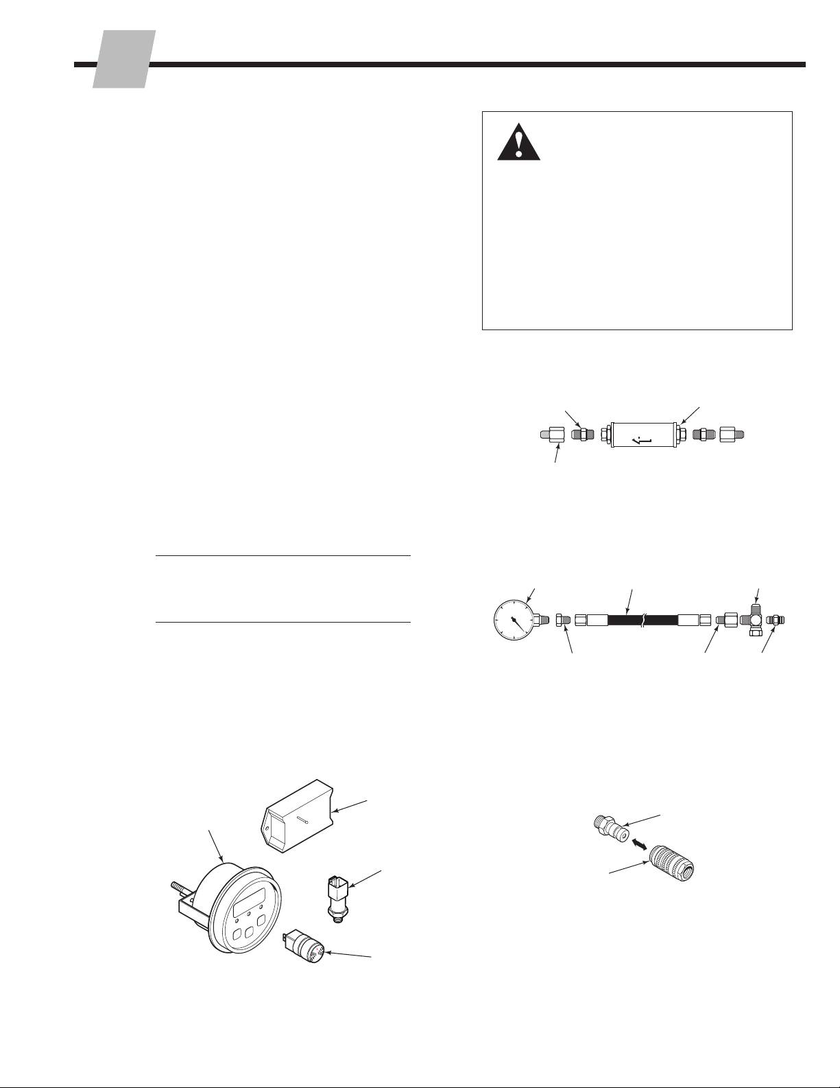
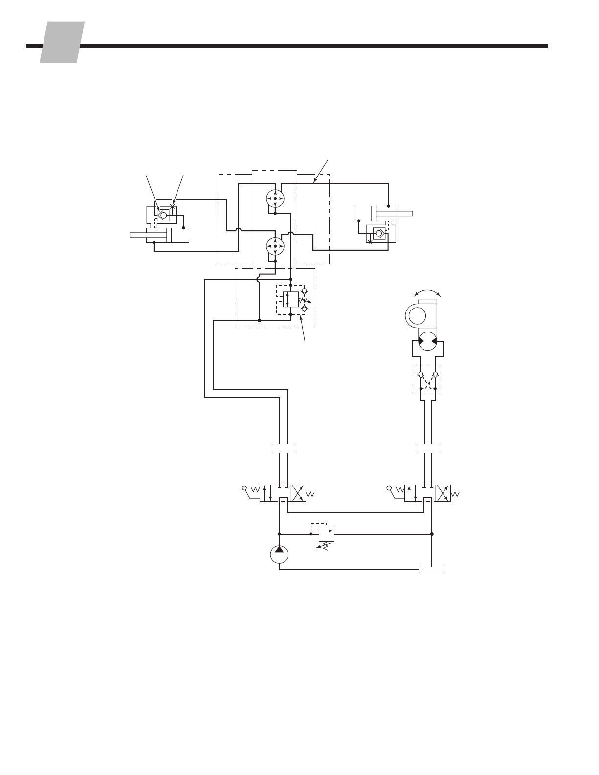
• Check that load-holding hydraulic system is functioning
properly. For this test, Cascade Clamp Force Indicators
300G-DFI-812C and 300G-CFI-812C are available.
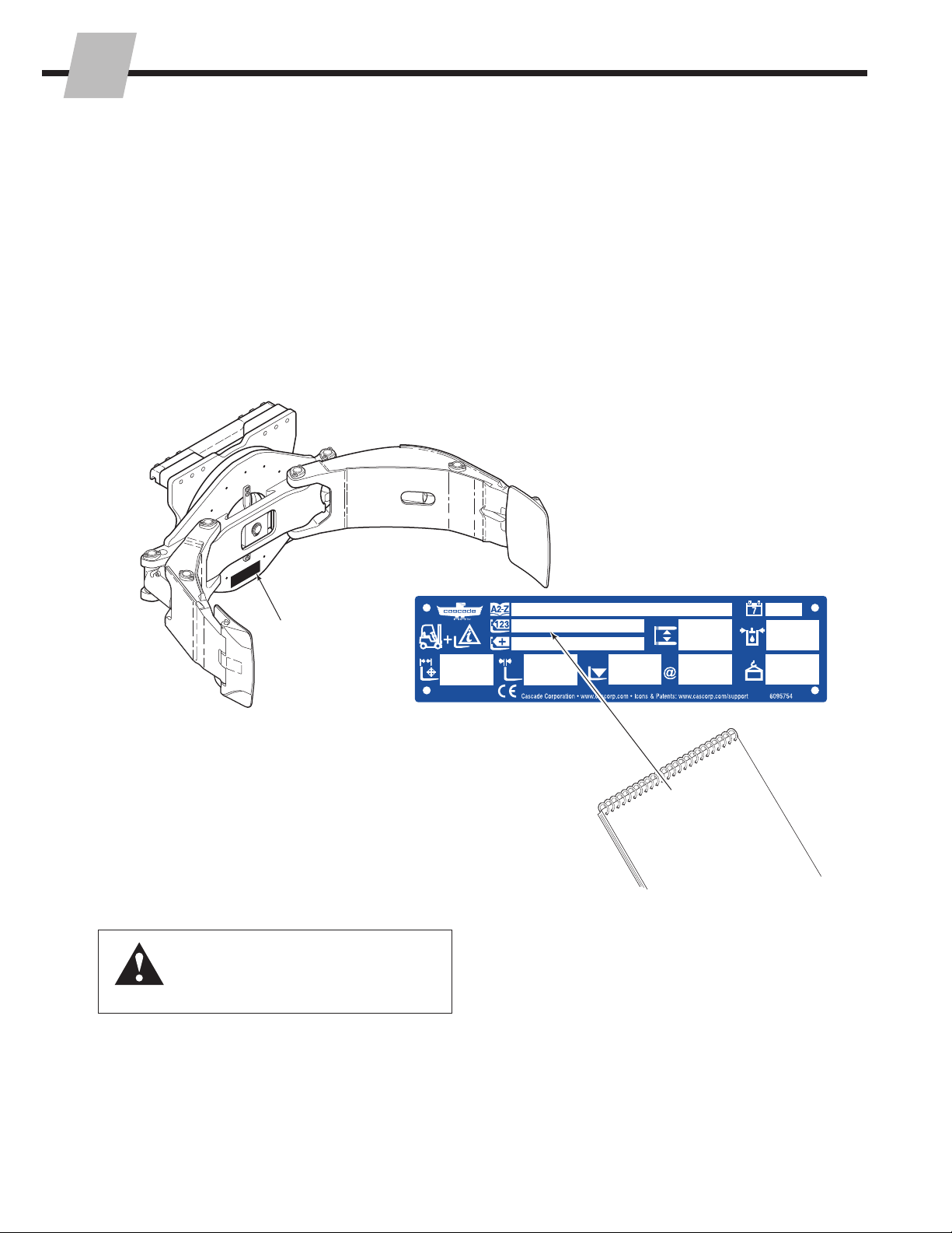
• Check decals and nameplate for legibility.
2.2 500-Hour Maintenance
After each 500 hours of truck operation, in addition to the
100-hour maintenance, perform the following procedures:
• Tighten lower mounting hook capscrews to 122 ft.-lbs.
(165 Nm).
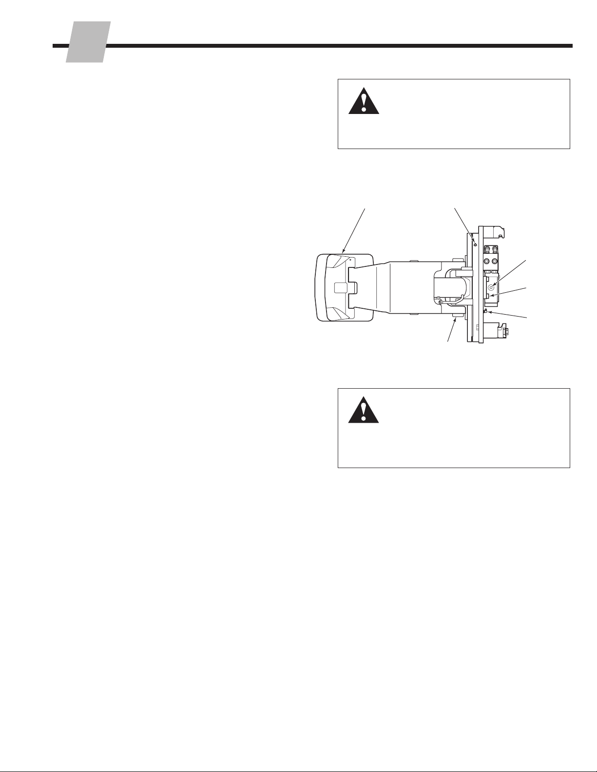
• Tighten rotator drive capscrews to 24 ft.-lbs. (32 Nm).
• Lubricate rotator bearing assembly ball race (A) and
gear (B) with EP-2 grease. (Whitmore 'Omnitask' or
equivalent). Rotate attachment in 90° increments and
grease in each position.
• Initial 500 Hours – Check rotator drive gearcase
lubricant level (remove vent cap). Oil should be filled
up to the bottom of the fill plug hole. Add oil through
the fill plug hole. If necessary, fill with Cascade Rotator
Drive Lubricant, Part No. 656300 or SAE 90 wt. gear
lube (AGMA 'mild' 6 EP Gear Oil). Replace the plug.
• Inspect all arm, frame and cylinder pivot bushings for
wear. Replace if necessary.
• Inspect all load-bearing structural welds on arms,
arm pivots and cylinder pivot areas for visual cracks.
Replace components as required.
• Inspect wear tile, arm tips and contact pads for wear
and damage. Replace or repair, as needed. Refer to
Section 4.2.
Contact Pad
Edges
Fill and
Level Hole
Rotator
Drive
Capscrews
Gear
Grease
Filling (B)
Ball Race Grease
Fitting (A)
Arm, Cylinder
Pivot Joints
WARNING: A sampling of rotation
capscrews must be checked for proper
torque at 500 hours (see TB183). A
complete inspection is required every
2000 hours. Failure to keep the capscrews
tightened can result in attachment damage
and serious injury.
10H
Left Side
RC5141.eps

6862661-R1
ERIODIC MAINTENANCE
P
3
2.4 2000-Hour Maintenance
After each 2000 hours of truck operation, in addition to
the 100, 500 and 1000-hour maintenance, perform the
following procedures:
• Check all rotation bearing capscrews for proper torque
value. Refer to Service section 4.9-2 for replacement
procedures.
• Inspect all arm and cylinder pivot pins for wear and
replace if necessary.
• Check the gearcase oil level (remove the cap). Oil must
be up to the bottom of the fill plug hole. Add oil through
top fill hole. If necessary, fill with Cascade Gear Lube
Part No. 656300, or SAE 90 wt. gear lube (AGMA 'mild'
6 EP Dear Oil). Replace plug.
2.5 4000-Hour Maintenance
After each 4000 hours of truck operation, in addition to
the 100, 500 and 2000-hour maintenance, perform the
following procedures:
• Due to normal mechanical wear and component service
life, cylinder seals should be replaced to maintain
performance and safe operation.
Upper Hook
Capscrews
Access Hole
for Faceplate
Rotation Bearing
Capscrews
Fill and
Level Hole
Rotator Drive
Capscrews
Lower Bolt-On
Hook Capscrews
Baseplate
Rotation
Bearing
Capscrews
Lower Quick-Disconnect
Hook Capscrews
10H
Back (Driver's) Side
Drain
Plug
2.3 1000-Hour Maintenance
After the initial 1000 hours of truck operation, in addition to
the 100 and 500-hour maintenance, perform the following
procedure:
• Initial 1000 Hours – Check rotator drive gearcase
lubricant level (remove vent cap). Oil should be filled
up to the bottom of the fill plug hole. Add oil through
the fill plug hole. If necessary, fill with Cascade Rotator
Drive Lubricant, Part No. 656300 or SAE 90 wt. gear
lube (AGMA 'mild' 6 EP Gear Oil). Replace the plug.
RC5331.eps

6862661-R1
ROUBLESHOOTING
T
4
3.1 General Procedures
3.1-1 Truck System Requirements
• Truck hydraulic pressure should be within the range
shown in Specifications, Section 5.1. Pressure to the
attachment must not exceed 2300 psi (160 bar).
• Hydraulic flow should be within the volume range as
shown in Specifications, Section 5.1.
• Hydraulic fluid supplied to the attachment must meet the
requirements as shown in Specifications, Section 5.1.
3.1-2 Tools Required
In addition to a normal selection of hand tools, the following
will be required:
• Inline Flow Meter Kit:
20 GPM (75 L/min.) - Cascade Part No. 671477.
• Pressure Gauge Kit:
5000 psi (345 bar) - Cascade Part No. 671212. Two kits
are required.
OR
Wireless Pressure Monitor:
Pressure transducers monitor the hydraulic pressure,
data is transmitted wirelessly to the receiver/display.
• Assorted fittings and hoses to adapt the gauges and
flowmeter to the components being tested.
WARNING: Before servicing any
hydraulic component, relieve pressure
in the system. Turn the truck off and
move the truck auxiliary control valves
several times in both directions.
After completing any service procedure, test the
attachment through several cycles. First test the
attachment empty to bleed any air trapped in the
system to the truck tank. Then test the attachment
with a load to be sure it operates correctly before
returning to the job.
Stay clear of the load while testing. Do not raise
the load more than 4 in. (10 cm) off the floor while
testing.
Pressure Gauge Kit 671212
Wireless Pressure Monitor Kits
Pressure
Gauge ▲
No. 6 and No. 8
JIC Swivel Tee
No. 4-6 Pipe/JIC ▲
No. 6-6 Hose ▲
Flow Meter Kit 671477
(2) No. 6-8 JIC Reducer
Flow Meter
No. 4, No. 6 ▲
and No. 8
JIC/O-Ring
No. 6-8 JIC
Reducer
(2) No. 8-12 JIC/
O-Ring
Diagnostic Quick-Disconnects
Male Straight Thread
O-Ring Coupler:
No. 4 (Part No. 212282)▲
No. 5 (Part No. 210378)
No. 6 (Part No. 678592)
Female JIC Thread Coupler:
No. 4 (Part No. 210385) ▲
No. 6 (Part No. 678591)
▲Included in Diagnostics Kit 394382.
GA0013.eps
GA0014.eps
AC0127.eps
AC1983.eps
Receiver/Display
Pressure
Transducer
Alarm
(if equipped)
Transmitter
One Pressure Transducer
Voltage Kit Part No.
12V 6803614, 6815672 ★
24-48V 6803617, 6815675 ★
Two Pressure Transducers
Voltage Kit Part No.
12V 6803615, 6815673 ★
24-48V 6803618, 6815676 ★
★ Includes alarm

ROUBLESHOOTING
6862661-R1
T
5
3.1-3 Troubleshooting Chart
Determine All The Facts – It is important that all the
facts regarding the problem are gathered before
beginning service procedures. The first step is to
talk to the equipment operator. Ask for a complete
description of the malfunction. The following
guidelines can then be used as a starting point to
begin troubleshooting procedures:
Clamp Circuit
• Attachment drops roll after it has been picked up.
• Attachment will not carry rolls to its rated capacity.
• Attachment arms will not function properly.
To correct one of these problems, see Section 3.3.
Rotate Circuit
• Attachment will not rotate.
• Attachment will not rotate rolls up to its rated
capacity.
• Attachment rotates in one direction only.
To correct one of these problems, see Section 3.4.

6862661-R1
ROUBLESHOOTING
T
6
RC5814.eps
3.2 Plumbing
3.2-1 Hosing Diagram
Rotator
Drive
Rotator
Drive
CCW
CW
Long Arm
Cylinder
Short Arm
Cylinder
(if equipped)
CLAMP
OPEN
Internal
Hose Reeving
Internal
Hose Reeving
Revolving
Connection
ROTATE
Truck
Auxiliary
Valve
ROTATE
Truck
Auxiliary
Valve
CLAMP
Truck
Auxiliary
Valve
CLAMP
Truck
Auxiliary
Valve
CLOSE ARMS
PRESSURE
RETURN
NOTE: For OPEN ARMS, reverse
the colors shown.
ROTATE CLOCKWISE
PRESSURE
RETURN
NOTE: For ROTATE COUNTER-
CLOCKWISE, reverse the colors
shown.
NOTE: Short arm cylinders
operate only when the
attachment is rotated to the
45-degree position.

ROUBLESHOOTING
6862661-R1
T
7
RC5815.eps
3.2-2 Hydraulic Schematic
Test PortCheck Valve
Revolving
Connection
Internal
Hose
Reeving
Internal
Hose
Reeving
Check
Valve
CLAMP Truck
Auxiliary Valve
ROTATE Truck
Auxiliary Valve
Truck Pump
Rotator Drive Motor
Relief
Cartridge
Valve
Long Arm
Cylinder
Truck Tank
Truck Relief
Valve
Short Arm
Cylinder
(if equipped)
CL
CL
CL
OP
OP
OP

6862661-R1
ROUBLESHOOTING
T
8
RC0349.eps
Clamp Circuit Test Continued, Step 2 Continued
• If the gauge pressure drops more than 150 psi
(10 bar) initially and an additional drop exceeds
25 psi (2 bar) per minute, the cylinder check valve
cartridge or piston seals may be faulty. Continue
troubleshooting, Step 3.
• If the gauge pressure does not drop more than
150 psi (10 bar) initially, and additional drop does
not exceed 25 psi (2 bar) per minute, the problem is
not hydraulic. Refer to Section 3.3.
3 Position both arms to midstroke to relieve cylinder
pressure. Remove, swap or reinstall the cylinder check
valve cartridge.
4 Long Arm Cylinder – Close the long arm fully and hold
the handle in the CLAMP position a few seconds to
develop full truck system pressure. Watch the gauge
pressure readings.
Short Arm Cylinder – Rotate the attachment to the 45°
position. Close the short arm fully and hold the handle
in the CLAMP position a few seconds to develop full
truck system pressure. Watch the gauge pressure
readings.
• If the gauge pressure on the cylinder continues
to drop more than 150 psi (10 bar) initially, and
additional drop exceeds 25 psi (2 bar) per minute, the
cylinder piston seals are faulty. Refer to Section 4.7
for cylinder service.
• If the gauge pressure on the cylinder does not drop
more than 150 psi (10 bar) initially, and additional
drop does not exceed 25 psi (2 bar) per minute,
the check valve (now in the other cylinder) is faulty
and requires replacement. Refer to Section 4.7-3 for
check valve service.
3.3 Clamp Function
There are four potential problem areas that can affect the
clamp function:
• Operator may be handling roll incorrectly. Loads may
be too heavy, exceeding capacity of the attachment.
Refer to the attachment's Operator’s Guide (Cascade
part no. 210135) for suggested procedures.
• Low hydraulic pressure or flow from lift truck.
• External leaks.
• Worn/defective revolving connection shaft seals,
cartridge valves, cylinder seals or check valves.
3.3-1 Supply Circuit Test
WARNING: Before removing hydraulic
lines, relieve pressure in the hydraulic
system. Turn the truck off and open the
truck auxiliary control valves several times
in both directions.
1 Check for external leaks at the cylinders and revolving
connection.
2 Long Arm Cylinder –Install a pressure gauge to the
long arm cylinder's test port. Close the long arm and
hold the handle in the CLAMP position a few seconds
to develop full truck system pressure. Watch the gauge
pressure reading.
Short Arm Cylinder – Install a pressure gauge to the
short arm cylinder's test port. Rotate the attachment to
the 45° position. Close the short arm fully and hold the
handle in the CLAMP position a few seconds to develop
full truck system pressure. Watch the gauge pressure
reading.
• If the initial gauge pressure is not within 100 psi
(7 bar) of system pressure measured at the hose
terminal, the revolving connection may be faulty and
require service. Refer to Section 4.6.
WARNING: Before removing hydraulic
lines, position both arms at midstroke to
relieve cylinder pressure. Turn the truck off
and open the truck auxiliary control valves
several times in both directions.
Pressure
gauge
Test
port
plug
Arm Cylinder
1 Check the pressure delivered by the truck. Refer to
the truck service manual. The pressure must be within
100 psi (7 bar) of specified truck pressure. Pressure to
the attachment must not exceed 2300 psi (160 bar),
measured at the carriage hose terminal.
2 Check the flow volume at the carriage hose terminal.
See Section 5.1-1 for recommended flow volumes. If
the truck pressure and flow are correct, proceed with
the CLAMP/OPEN circuit pressure test.
3.3-2 Clamp Circuit Test

ROUBLESHOOTING
6862661-R1
T
9
3.4 Rotation Function
There are four potential problem areas that can affect the
rotation function:
• Operator may be handling roll incorrectly. Loads may
be too heavy or rotated off-center, exceeding capacity of
attachment. Refer to the attachment's Operator’s Guide
(Cascade part no. 210135) for suggested procedures.
• Low hydraulic pressure or flow from lift truck.
• Worn or defective hydraulic rotator motor.
• Worn or defective drive assembly or rotator frame
bearing assembly.
3.4-1 Supply Circuit Test
WARNING: Before removing hydraulic
lines, relieve pressure in the hydraulic
system. Turn the truck off and open the
truck auxiliary control valves several times
in both directions.
Install
pressure
gauges
Install
flowmeter
1 Check for external leaks.
2 Check the pressure delivered by the truck. Refer to
the truck service manual. The pressure must be within
100 psi (7 bar) of specified truck pressure. Pressure to
the attachment must not exceed 2300 psi (160 bar),
measured at the carriage hose terminal.
3 Check the flow volume at the carriage hose terminal.
See Section 5.1-1 for recommended flow volumes.
If the truck pressure and flow are correct, proceed with
the ROTATE circuit pressure test.
3.4-2 Rotation without Load
1 Install pressure gauges on the rotator motor fittings.
2 Rotate the attachment without a load and note pressure
readings of both gauges.
• If the attachment rotates in one direction faster than
the other, or rotates in one direction only, the drive
box may need service. Refer to Section 4.3.
• If the lower gauge reading exceeds 500 psi (35 bar),
there is excessive back pressure in the supply
circuit. Check for restrictions such as numerous
fittings, 90° fittings, or hose sizes less than No. 6.
RC5174.eps
RC5175.eps

6862661-R1
ROUBLESHOOTING
T
10
3.4-3 Rotation with Load
1 Select a load that is approximately 3/4 of the
attachment's maximum torque capacity:
10H – 20,860 in.-lbs. @ 2300 psi
(2355 Nm @ 160 bar)
10H (low flow) – 13,689 in.-lbs. @ 2300 psi
(1545 Nm @ 160 bar)
Use the chart as a guideline to determine the
approximate roll diameter and roll weight to achieve the
3/4 torque capacity.
2 Rotate the load. Note gauge readings during rotation.
• If the higher gauge reading is substantially less than
the truck pressure as measured at the carriage hose
terminal, the drive motor geroler set may need repair.
Refer to Section 4.4.
• If the higher gauge reading is close to truck pressure
as measured at the carriage hose terminal and no
rotation occurs, the drive motor output shaft or drive
box may need repair. Continue troubleshooting.
2 Remove the motor from the drive box assembly as
described in Section 4.4-1.
3 Reinstall the hoses to the drive motor fittings. Actuate
the rotate circuit.
• If the drive motor shows rotational output, the drive
box may require service. Refer to Section 4.3.
• If the drive motor shows little or no rotational output,
the drive motor requires service. Refer to Section 4.4.
3.4 Rotation Function (continued)
10H – 3/4 of maximum torque capacity:
15645 in.-lbs. @ 2300 psi (1326 Nm @ 160 bar)
US Metric
Roll
Diameter Roll weight
Roll
Diameter Roll weight
20 in. 782 lbs. 510 mm 3463 N
30 in. 522 lbs. 762 mm 2318 N
40 in. 391 lbs. 1016 mm 1738 N
50 in. 313 lbs. 1270 mm 1391 N
60 in. 261 lbs. 1525 mm 1158 N
10H (low flow) – 3/4 of maximum torque capacity:
10267 in.-lbs. @ 2300 psi (1159 Nm @ 160 bar)
US Metric
Roll
Diameter Roll Weight
Roll
Diameter Roll Weight
20 in. 513 lbs. 510 mm 2272 N
30 in. 342 lbs. 762 mm 1521 N
40 in. 257 lbs. 1016 mm 1141 N
50 in. 205 lbs. 1270 mm 912 N
60 in. 171 lbs. 1525 mm 760 N

ROUBLESHOOTING
6862661-R1
T
11
RC0736.eps
3.5 Electrical Circuit
(Solenoid-equipped attachments)
Use the schematic shown and follow the steps below.
1 Check the control knob circuit fuse. Replace if
necessary.
2 Check for loose electrical connections at the truck
ignition switch, control knob button, solenoid coil
terminals and diode.
3 Remove the diode from the solenoid coil terminal. Test
with an ohmmeter for high resistance in one direction
and no resistance in the other direction. If there is no
resistance in both directions, replace the diode.
NOTE: When replacing the diode, the banded (+) end
must connect to the positive (+) side of the coil and
wiring as shown.
4 Use a voltmeter to determine if correct voltage is
present at the electrical leads when the button is
pressed.
• If there is no voltage at the solenoid, troubleshoot the
electrical circuit for shorts or open circuits.
• If there is insufficient voltage to the solenoid, check
the circuit for excessive voltage drop.
• If there is sufficient voltage to the solenoid, test for
coil continuity. Continue to Step 5.
5 Test the coil continuity by placing an ohmmeter test lead
on each solenoid coil terminal (ohmmeter on Rx1 scale).
• If there is an ohmmeter reading, the coil is good.
• If the coil is good, but the solenoid does not 'click'
when the control knob button is pressed, the
solenoid cartridge may be jammed.
• If there is no ohmmeter reading, the coil is defective.
Replace coil.
7.5 Amp
Fuse
Push Button
Black
Coil
Diode
Diode
IMPORTANT: Banded
end must connect to
positive (+) side of
circuit.
Control Knob
with Push Button
12V: 2.4–2.8 Ohm
24V: 9.5–11 Ohm
36V: 24–28 Ohm
48V: 40–46 Ohm
Push button attached
to control lever with
heat shrink tubing Solenoid Coil Solenoid Valve
Cable
White

6862661-R1
ERVICE
S
12
RC5177.eps
ADJUST
RC0368.eps
Open
Rotate CCW
Rotate CW
Clamp
Guide
Hook
QUICK-CHANGE HOOKS
Carriage Bar
LH lower
Hook
1
3
3BOLT-ON HOOKS
2
4.1 Attachment Removal
1 Rotate the attachment to the vertical roll handling
position. Extend the arm outside the frame width.
WARNING: Before removing hydraulic
lines, relieve pressure in the hydraulic
system. Turn the truck off and open the
truck auxiliary control valves several times
in both directions. 4
2 Disconnect and plug the hydraulic supply hoses to the
attachment. Tag hoses for reassembly.
3 Disconnect/remove the lower hooks:
Bolt-On Hooks – Remove the lower mounting hooks.
For reassembly, apply Loctite 242 (blue) on the
capscrew threads. Tighten the capscrews to 122 ft.-lbs.
(165 Nm).
Quick-Change Hooks – Pull out pin and rotate hook
down. Release pin. For reassembly, pull pin and rotate
hook up. Release pin.
4 Set the attachment on a pallet. Tilt the mast forward
and lower the carriage to remove the attachment from
the truck.
5 For installation, reverse the above procedures with the
following exceptions:
• Refer to Installation Instructions manual 6077316 for
complete installation procedures.
RC5132.eps
RC5334.eps

6862661-R1
ERVICE
S
13
RC5213.eps
4.2 Arm
4.2-1 Arm Assembly –
Removal and Installation
1 Rotate the attachment to the vertical roll handling
position.
2 Remove the retainer and cylinder rod anchor pin
from the arm being removed. Retract the cylinder
rod. For reassembly, tighten the retainer capscrews
to 28 ft.-lbs. (38 Nm).
3 Swing the arm inward to contact the other arm.
Rotate the attachment 90° to position the arm being
removed on top.
4 Attach an overhead hoist to the arm and take up
slack in the chain or strap.
5 Remove arm/faceplate retainers and arm pivot pins.
Note location of shims. Lift away arm assembly. For
reassembly, tighten the pivot pin retainer capscrews
to 28 ft.-lbs. (38 Nm).
6 For reassembly, reverse the above procedures.
2
1
4
5
3
WARNING: Verify that the overhead
hoist and chains or straps are rated for
the weight of the attachment. Refer to
nameplate for attachment weight.
RC3672.eps

6862661-R1
ERVICE
S
14
RC3664.eps
Pivot Pin
Drive Pin
Capscrew
Spring
Clevis Pin
Link
Cotter Pin
4.2-2 Contact Pad –
Removal and Installation
1 Rotate the attachment to the vertical roll handling
position. Lower the unit until the contact pads are
approximately 1 in. (25 mm) off the ground.
2 Remove cotter pins from the clevis pins that fasten
the links to the contact pad. Remove the clevis pins
from the links while detaching the springs. Springs will
remain fixed to the arms.
3 Remove the drive pins from the contact pad pivot points
and remove the pivot pins.
4 Remove the contact pad. Pad links can be removed
from the arm by rotating 90° and pulling out.
5 For reassembly, reverse the above procedures with the
following exceptions:
• Inspect the arm tips and pivot pins for wear and
repair/replace as necessary.
• Install pivot pin and top drive pin. Make sure drive
pin is an interference fit. Pin is 0.33 in. (8.4 mm)
diameter x 1.50 in. (38.1 mm) long.
• Check the condition of the springs. Replace as
required.
2
2
3
3
RC5264.eps
4.2-3 Wear Tile Replacement
1 Position the wear tiles on the back of the short arm
using the dimensions shown. Tack, then weld the wear
tiles using the weld procedures described on Section
4.2-4, Step 8.
2 Remove slag after each weld and inspect for defects.
NOTE: Arc craters, undercut, overlap and porosity are
not permitted. Repair any defect as required.
3 Grind all welds to smooth transitions between parts.
4 Install contact pads by reversing Steps 1 through 4 of
Removing Contact Pads.
0.15 in. (4.0 mm)
No sharp
edges
Wear Tile
6810046
0.50 in.
(13 mm)
0.50 in.
(13 mm)
1

6862661-R1
ERVICE
S
15
RC3960.eps
RC3956.eps
RC3957.eps
RC5266.eps
4.2-4 Arm Tip Repair
1 Place the tool against the tip with raised ribs on the
inner arm surface and the spacers in between each tip.
Tack weld two blocks (user equipped) to the inside of
the arm as a marker at the edge of the tool. Remove the
tool.
IMPORTANT: Avoid damage to machined features and
threaded holes.
Marker Block
Kit Tool
Kit Tool
Tool
Arm
Arm
Remove tips of
arm casting
Tack Weld
Cut Line
Arm Inside
Marker
Block
Marker
Block
0.20 ±0.03 in.
(5.0 ±0.7 mm)
0.20 ±0.03 in.
(5.0 ±0.7 mm)
4 Clamp the kit tool against the marker blocks.
1
3
2
2 Scribe a cut line 0.20 ±0.03 in. (5 ±0.7 mm) back from
the inner surface of the existing tip holes on both sides
of the arm tips.
3 Remove defective tip area entirely at the cut line by
grinding, sawing, torch or arc gouging. Remove any
paint contamination from around the repair area. If arc
gouging is used, make sure all carbon particles are
completely removed.

6862661-R1
ERVICE
S
16
4.2-4 Arm Tip Repair (Continued)
8 Finish-weld the tubes to the arm tips and wear tiles
using the following weld procedures:
• Protect inside of tubes from weld spatter.
• Preheat arm tip base metal to 150°F (66°C). Monitor
and maintain arm tip heat at locations shown using
suitable temperature-indicating devices.
• Weld Sequence – Start weld on side indicated.
Terminate each weld at center of tube.
• WELD METHOD A – FCAW (Flux-Cored Arc Weld).
Attach ground wire to arm. Weld using AWS E70T-1
1/16 in. (1.6 mm) or 5/64 in. (2 mm) diameter wire
with 100% CO2 shielding gas at 35-50 CFH. Set
welding amp per manufacturers recommendations.
Apply weld holding a close arc. Do not oscillate or
use a wash bead pattern.
WELD METHOD B – SMAW (Stick Welding). Attach
ground wire to arm. Weld using E-7015 low hydrogen
1/8 in. (3.2 mm) or 5/32 in. (4.0 mm) diameter
electrodes. Set welding amps per manufacturer’s
recommendations. Do not use electrode exposed to
moisture without first re-drying them at 200°F (75°C)
for 2 hours. Apply weld holding a close arc. Do not
oscillate or use a wash bead pattern.
• Cool arm tip base metal at normal air cool.
• Remove marker blocks. Smooth out tack weld spots.
6 Preheat arm tip base metal to 70°F (21°C) minimum.
Tack weld new tubes to the tips. Use the recommended
weld procedures listed in step 8. Remove kit tool.
7 Install the contact pad and pivot pin on the arm. Check
the tube alignment, realign as required. Remove the
contact pad and pin.
5 Position the new tubes on the arm tips using the kit tool.
Place existing pivot pin through all tubes and kit tool for
alignment. All repairs should be done in the flat position.
RC3961.eps
RC4574.eps
RC5236.eps
Pivot Pin
Tubes and
Kit Tool
Start weld this side
Temperature
Measurement
Areas
0.40 in. (10.0 mm)
Align new tubes
flush with outer
edge of casting
2.0 in.
(50.0 mm)
5
START
STOP
START 8
8
Weld Sequence
7.77 in.
(182.3 mm)

6862661-R1
ERVICE
S
17
RC5189.eps
4.3 Drive Group
4.3-1 Drive Group Removal
and Installation
1 Remove the attachment from the truck as described in
Section 4.1.
2 Remove the valve from the motor and baseplate as
described in Section 4.5.
3 Remove the four capscrews fastening the drive group
to the baseplate. For reassembly, clean and dry
capscrews. Apply Loctite 242 (blue) to threads and
tighten the capscrews to 25 ft.-lbs. (32 Nm).
4 For reassembly, reverse the above procedures with the
following exceptions:
• After the drive group has been reinstalled, check
the gearcase oil level. Oil must be up to the bottom
of the oil level hole. Add oil through the cover vent
hole. If necessary, fill with Cascade Gear Lube Part
No. 656300, or SAE 90 wt. gear lube (AGMA 'mild' 6
EP Gear Lube).
4.3-2 Drive Group Disassembly
and Service
1 Drain oil from the housing drain hole.
2 Remove the drive group from the baseplate as
described in Section 4.3-1.
3 Lay the drive group, pinion down, on two 4 x 4 in.
(10 x 10 cm) wood blocks placed on both sides of
the pinion.
4 Remove the four capscrews fastening the cover plate to
the housing.
5 Remove the center capscrew plug from the cover plate
and install an 3/8 NF capscrew with a minimum thread
length of 2 in. (50 mm). Remove the cover plate by
turning the capscrew clockwise while lightly tapping
around the sides of the cover plate.
6 Remove the four capscrews fastening the end cover to
the housing.
7 Remove the drive motor as described in Section 4.4-1.
Cover
Plate 4
5
3
7
1
6
Housing
End Cover
Housing
RC5178.eps
23
Oil Level
Hole with
Vent Cover
Drain Plug
4
Table of contents
Other cascade corporation Industrial Equipment manuals