Spring Well SPRW-UV4-2 User manual

Operaon & Installaon Instrucons
UV4
Series
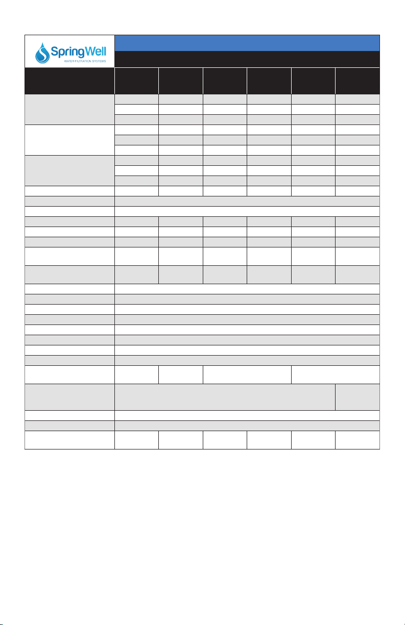
SpringWell - Standard Systems
System Rated Flow System Rated Flow
SPRW-UV4-2
SPRW-UV5-2
SPRW-UV6-2
2 gpm
SPRW-UV4-5C
SPRW-UV5-5C
SPRW-UV6-5C
5 gpm
SPRW-UV4-3
SPRW-UV5-3
SPRW-UV6-3
3 gpm
SPRW-UV4-10C
SPRW-UV5-10C
SPRW-UV6-10C
10 gpm
SPRW-UV4-6
SPRW-UV5-6
SPRW-UV6-6
6 gpm
SPRW-UV4-15C
SPRW-UV5-15C
SPRW-UV6-15C
15 gpm
SPRW-UV4-11
SPRW-UV5-11
SPRW-UV6-11
11 gpm
SPRW-UV4-25C
SPRW-UV5-25C
SPRW-UV6-25C
25 gpm
SPRW-UV4-15
SPRW-UV5-15
SPRW-UV6-15
15 gpm
SPRW-UV4-40C
SPRW-UV5-40C
SPRW-UV6-40C
40 gpm
SPRW-UV4-21
SPRW-UV5-21
SPRW-UV6-21
21 gpm
UV5/6
Series
UV4-C
Series
UV5/6-C
Series

2|Page
Congratulaons on purchasing this
ultraviolet disinfecon system.
By purchasing a SpringWell UV Disinfecon system, you are
receiving not only a high quality product but also peace of
mind. Protecng your water supply with a UV system gives you
reassurance that your family will have access to safe drinking
water throughout your enre home with no chance of
microbiological contaminaon. This is a chemical free process
which is simple in its concept and eecve in its abilies to
inacvate microorganisms present in the water supply. Simple
maintenance, connuous disinfecon and ulmately safe
water, SpringWell Water Filtraon Systems makes it that easy.

3|Page
TABLE OF CONTENTS
Safety Consideraons ......................................................................................................... 4
Before You Begin ................................................................................................................ 4
Water Quality Parameters .................................................................................................. 5
Assembly ............................................................................................................................ 6
System Sizing ...................................................................................................................... 8
Locaon .............................................................................................................................. 8
Installaon ......................................................................................................................... 9
System Disinfecon .......................................................................................................... 11
Cleaning the Quartz Sleeve .............................................................................................. 11
Cleaning the UV Sensor .................................................................................................... 12
Operaon ......................................................................................................................... 13
UV4 Controllers ...................................................................................................... 13
UV5 & UV6 Controllers .......................................................................................... 13
UV5 & UV6 Power-up Sequence ............................................................................ 13
UV5 Operaonal Screens ....................................................................................... 14
UV6 Operaonal Screens ....................................................................................... 14
Lamp Countdown Sequence .................................................................................. 15
System Service Suggested ...................................................................................... 16
Lamp Replacement (UV4 systems) ........................................................................ 16
Lamp Replacement (UV5 & UV6 systems) ............................................................. 16
QR Codes ............................................................................................................... 16
System Troubleshoong......................................................................................... 17
Temperature Management Devices ................................................................................. 18
Expansion Modules .......................................................................................................... 19
Standard Output System Specicaons ........................................................................... 20
High Output System Specicaons ................................................................................... 21
Limited Warranty Statement ............................................................................................ 22
Warranty Registraon ...................................................................................................... 23

4|Page
Safety Consideraons
Although your UV system has been manufactured to the highest safety standards, care must be
followed when operang and/or maintaining your system.
1. Before servicing this equipment, disconnect the power cord from the electrical outlet.
2. Energy given o by the UV lamp is harmful to your eyes and skin. NEVER look directly
at an illuminated UV lamp without adequate eye protecon and always protect your skin
from direct exposure to the UV light.
3. For complete disinfecon, use ONLY genuine replacement parts.
4. Do not operate the unit if it has any damaged or missing components.
5. To avoid possible electrical shock, use only with a properly grounded electrical outlet.
6. Never perform any maintenance to the system unless you are comfortable in doing so.
Contact the manufacturer for service instrucons if required.
7. Do not use this system for any purpose other than what it was intended for. Misuse of this
system could potenally cause harm to the user or others.
8. Your system is intended to be installed indoors and away from leaking plumbing. DO NOT
plug the unit in if the system or any of the components are wet.
9. The disinfecon system should be directly installed into a ground fault circuit interrupter
(GFCI). If the use of an extension cord is required, the cord must be manufactured with a
minimum of 16 gauge wire and care should be taken to avoid potenal tripping hazards.
10. We recommend that a licensed plumber or cered technician install the system.
Before You Begin
The following will be needed for installing the UV system:
Tools
• Pipe cuer, hacksaw or other specialized tools required to cut into your exisng
plumbing (e.g. if you have PEX piping)
• Soldering tools (torch, ux, emery cloth and solder)
• Wrench (for ghtening ngs)
Other Materials
• Inlet/outlet connecons
• Teon™ tape

5|Page
Water Quality Parameters
UV disinfecon is extremely eecve against microorganisms but only if the UV light can pass
through the water it needs to treat. This means that the quality of your water is very important
in order to ensure complete disinfecon.
Treated water should be tested for at the least the parameters listed below. If the water
exceeds the listed parameters SpringWell strongly recommends that appropriate pretreatment
equipment be installed (equipment required will depend on parameters being treated):
Hardness: <7 gpg (120 mg/L) – if hardness level is 7 gpg or slightly below the
quartz sleeve must be cleaned periodically in order to ensure e-
cient UV penetraon; if above the water must be soened.
Iron (Fe): <0.3 ppm (0.3 mg/L)
Manganese (Mn): <0.05 ppm (0.05 mg/L)
Turbidity: < 1 NTU
Tannins (organics): <0.1 ppm (0.1 mg/L)
UVT (transmiance): >85% (Please contact SpringWell if water has a UVT that is less than
80% for pre-treatment recommendaons)
You can have your water tested at a private analycal laboratory or by your local dealer. It is
always recommended to install pre-ltraon of at least 5 microns prior to a UV disinfecon
system.

6|Page
Assembly
Unpack the system and ensure all the components are included with the system. Your system is
shipped with the following components:
STANDARD OUTPUT
LAMP SYSTEMS
LAMP
KEY
CLAMPS
CONTROLLER
UV4 Systems
SPRW-UV-NE1
UV5 & UV6 Systems
SPRW-UV-N1
GLOW PLUG
300016 Complete Assembly
310026 Teon Plug
310040 O-Ring
390007 Brass Nut
UV SENSOR
SPRW-UV-NS1
UV5/6 series
“-02”, “-03”, “-06”, “-11”, “-15” series
SPRW-UV-NS2
“-21” series
GLAND NUT
320006
O-RING
300038
UV LAMP
SPRW-UV-210
SPRW-UV-290
SPRW-UV-470
SPRW-UV-820
SPRW-UV-850
SPRW-UV-999
SLEEVE SPRING
310039
QUARTZ SLEEVE
SPRW-UV-Q210
SPRW-UV-Q290
SPRW-UV-Q470
SPRW-UV-Q820
SPRW-UV-Q850
SPRW-UV-Q999
REACTOR
300083 “-02” series
300050 “-03” series
300052 “-06” series
300054 “-11” series
300061 “-15” series
300068 “-21” series

7|Page
HIGH OUTPUT
LAMP SYSTEMS
CONTROLLER
UV4-C Systems
SPRW-UV-HO-NE
UV5-C & UV6-C Systems
SPRW-UV-HO-N
GLOW PLUG
300016 Complete Assembly
310026 Teon Plug
310040 O-Ring
390007 Brass Nut
UV SENSOR
SPRW-UV-NS3
POWER CORD
260004 North American
260005 Euro
260006 Australian/New Zealand
260008 Brish
GLAND NUT
320006
O-RING
300038
UV LAMP
SPRW-UV-210HO “-05” series
SPRW-UV-330HO “-10” series
SPRW-UV-420HO “-15” series
SPRW-UV-600HO “-25” series
SPRW-UV-950HO “-40” series
SLEEVE SPRING
310039
QUARTZ SLEEVE
SPRW-UV-Q210 “-05” series
SPRW-UV-Q330 “-10” series
SPRW-UV-Q420 “-15” series
SPRW-UV-Q600 “-25” series
SPRW-UV-Q950 “-40” series
REACTOR
300062 “-05” series
300063 “-10” series
300064 “-15” series
300007 “-25” series
300009 “-40” series
LAMP
KEY
CLAMPS
8|Page
System Sizing
All UV systems are rated for a specic ow rate in water that meets the quality parameters on
page 5. PLEASE NOTE that increasing the ow above this rang or disinfecng water that does
not meet the quality parameters will decrease the dose and therefore compromise the micro-
organism inacvaon.
To determine ow rate follow these simple steps:
Be sure no water is being used in the home. Open a faucet or tap nearest the pressure system
and run unl the well pump starts. Close the faucet and using a second hand watch, record the
length of me in seconds unl the pump stops. This is known as the cycle me.
Then using a container of known volume, preferably in US Gallons, open the faucet or tap near-
est the pressure system and measure the amount of water drawn o unl the pump starts again.
Depending on the size of the container used, it is acceptable to turn the faucet on and o to
empty the container. This measurement is known as the draw down.
To calculate the pressure system ow rate divide the draw down by the cycle me and mulply
that by 60.
Draw Down__________÷ Cycle Time____________ x 60=__________Pumping Rate in USGPM
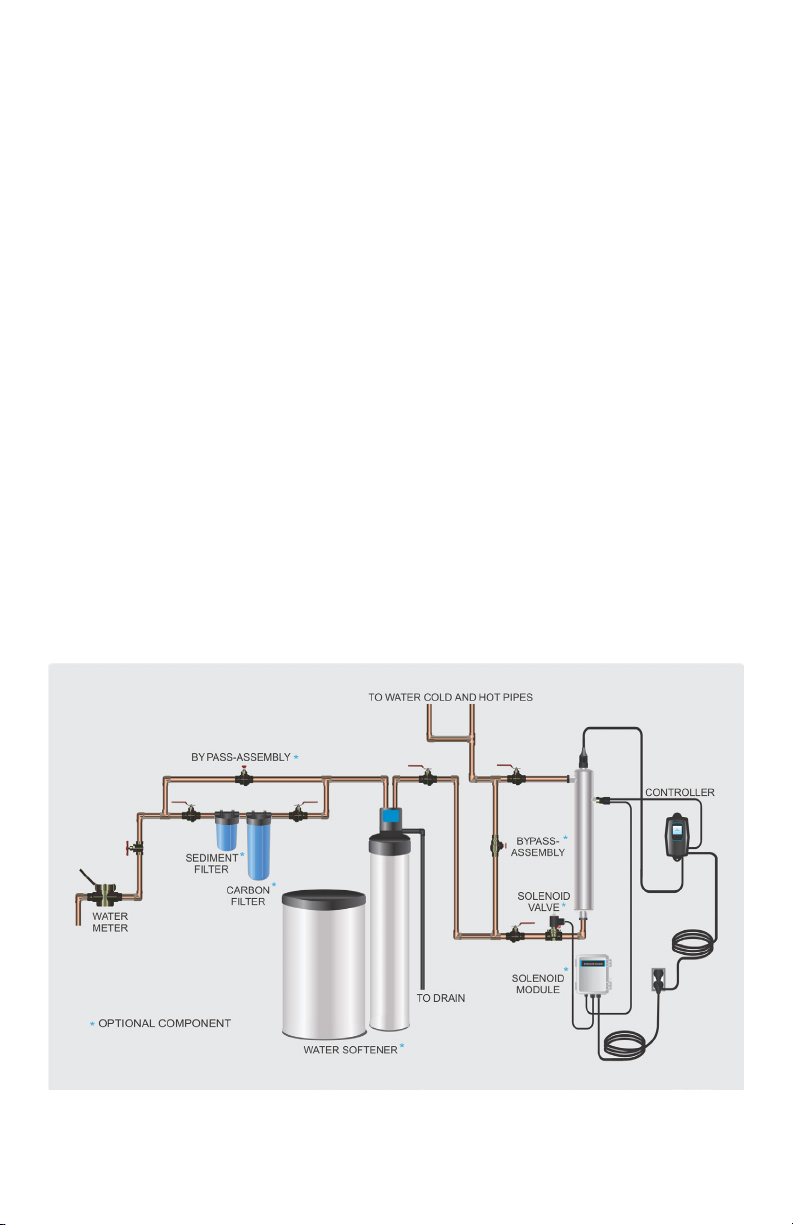
Locaon
For Point of Entry (POE) systems, choose a locaon where the main cold water line is accessible.
The system must be installed aer other water treatment equipment (soener or lters), but
before any branches (See Figure 1). For Point of Use (POU) systems, install the unit just before
the faucet. SpringWell recommends that a 5 micron lter be installed before the UV system for
a nal polishing step before the water is disinfected.
Figure 1. Recommended POE Installaon Locaon

9|Page
To facilitate lamp removal, ensure there is enough space at
the lamp connector end to safely remove the UV lamp and/
or quartz sleeve (See Figure 2). The controller will require
a ground fault circuit interrupter (GFCI or GFI) outlet and
should be mounted beside or above the reactor. PLEASE
NOTE: All UV disinfecon systems are intended for indoor
use only as they should not be exposed to the elements.
Installaon
Step 1: The reactor can be installed either horizontally or
vercally using the clamps provided. Vercal installaon is
the preferred method with the inlet at the boom (lamp
connecon at the top) as it allows any air that may be in the
lines to be easily purged from the system.
Step 2: The use of a by-pass assembly is recommended as
it will allow you to isolate the UV reactor. This will allow for
easier access in case maintenance is required (See Figure 3).
Step 3: Use the supplied fasteners to mount the UV
reactor to wood or drywall. If mounng to an alternate
material you will need to purchase the proper corresponding
fasteners.
Step 4: For water supplies where the maximum ow rate
is unknown, a ow restrictor is recommended so that the
rated ow of your parcular system is not exceeded. The
ow restrictor should be installed on the inlet port of the
reactor.
Step 5: It is recommended to have a licensed plumber
connect the UV reactor to the water supply and may be a
requirement depending on where you are located.
Step 6: Once the system has been plumbed in, gently
remove the quartz sleeve from its packaging being careful
not to touch the length with your hands. The use of coon
gloves is recommended for this procedure as oils from the
hands can leave residue on the sleeve and lamp which can
ulmately block the UV light from geng to the water.
Carefully slide the sleeve into the reactor unl you can feel
it hit the opposite end of the reactor. Align the sleeve so it
centered along the length of the reactor, then gently push it
in to lock it into the internal centering springs in the far side
of the reactor. CAUTION: Pushing too hard when the sleeve
is not aligned can damage the centering springs. Slide the o-
ring onto the sleeve unl it is bued up against the reactor.
Figure 2. Lamp
Removal Spacing
leave at least
an addional
reactor length
to facilitate
lamp and
sleeve removal
Note: Installaon of your disinfecon systems
shall comply with applicable provincial/state
& local regulaons.
Figure 3. By-pass
assembly

10|Page
Step 7: Hand ghten the provided gland nut over the quartz
sleeve onto the threaded end of the reactor. It has a posive
stop to prevent over-ghtening. A rm force may be required
to fully ghten the gland nut, but DO NOT USE TOOLS for this
step. Insert the provided stainless steel compression spring into
the quartz sleeve. The spring works with the lamp and lamp
connector to create the proper lamp alignment. PLEASE NOTE:
DO NOT install a UV lamp inside the quartz sleeve without the
sleeve spring in place.
Step 8: Install the UV sensor (ordered separately). Align the
at poron so it faces the gland nut end and matches up with
the half metal lip on the sensor port (see Figure 5). Insert the
sensor so it is fully seated and hand ghten the sensor nut.
Step 9: The reactor is now ready for water ow. When all
plumbing connecons have been completed, slowly turn on the
water supply and check for leaks. Make sure the by-pass valves
are funconing properly and that the water is owing through
the reactor. The most common leak is from the o-ring not making
a proper seal on the reactor. For new installaons, review steps 6
and 7. For older systems drain the reactor, remove the o-ring, dry
it and reapply silicon grease. Reinstall the o-ring ensuring that it is
properly sealed against the reactor and check again for leaks.
Step 10: Mount the controller to the wall so it is above or
beside the reactor to ensure that no moisture can deposit
on any of the connecons (see Figure 1). Always mount the
controller vercally. For monitored systems, insert the sensor
connector into the IEP port located on the right side of the
controller (Figure 6). For the sensor to be recognized by the
controller, the controller power must be plugged in last. Do not
plug the controller power cord in before the last step.
Step 11: Always hold UV lamps by their ceramic ends, not by
the lamp quartz. Remove the lamp from its packaging. Again,
the use of coon gloves is recommended. Remove the lamp key
from the lamp’s connector and set it aside for the next step. Be
careful to not touch the key’s exposed contacts. Insert the UV
lamp into the reactor, being careful not to drop it.
Step 12: Install the lamp key into the controller (UV5 & UV6
systems only). The key always comes packaged with the lamp
and sits on the connector. With the key removed from the lamp,
orient it so the label is upright and facing you. The key will plug
into the lamp key port on the right side of the controller (Figure
7).
Figure 4. Quartz
Sleeve Installaon
Figure 5. UV Sensor
Installaon
Figure 6. IEP
Connecon
Figure 7. Lamp Key
Installaon

11|Page
Step 13: Plug the lamp connector into the lamp. Note the
keying for proper alignment (see Figure 8a, 8b). Insert the
lamp connector into the gland nut and turn the connector
approximately ¼ turn to lock the connector to the gland nut as
in Figure 9.
Step 14: Tighten the capve ground screw to the ground lug
on the UV reactor to ensure proper grounding(Figure 10).
Step 15: Your system is now ready to be plugged into the
appropriate GFCI protected outlet. Refer to the following
secon before any water is allowed to ow through the system.
System Disinfecon
With a new installaon, or any me the UV system is shut
down for service, without power, or is inoperave for any other
reason, the lines in the home or facility could be contaminated.
Use the following steps to fully disinfect the lines throughout
the enre home or facility.
Step 1: Check for and remove any “dead ends” in the lines
throughout the home as these can harbor bacteria. Plug in the
UV system and wait unl it is ready for operaon.
Step 2: Remove the lter cartridge from the last sump and ll
it with 1-2 cups of household bleach (most are 5.25% chlorine).
Replace the sump and slowly turn on the water supply.
Step 3: At a water outlet, run the water unl bleach can
be smelled. Repeat this for all faucets, toilets, shower heads,
refrigerators, outdoor taps, the washing machine, dishwasher,
etc. at the home or facility. Once nished, wait a minimum of 30
minutes before connuing.
Step 4: Reinstall the lter cartridge into the sump and ush
the chlorine soluon by opening all faucets unl chlorine can
no longer be detected. Your home has now been completely
disinfected with your UV system ready to inacvate any
microorganisms that enter the home.
Cleaning the Quartz Sleeve
Depending on the water quality, the quartz sleeve may require
periodic cleaning. At a minimum, the quartz sleeve should be
cleaned on an annual basis. The following steps outline a basic
cleaning procedure.
Step 1: If a by-pass assembly is installed, shut the inlet valve
o to prevent water ow through the system. Otherwise, turn
o main water inlet valve (and/or turn o the water pump).
Step 2: Disconnect power cord of UV system from electrical
outlet.
Figure 8a. Standard
Output UV Lamp
Connecon
Figure 8b. High Output
UV Lamp Connecon
Figure 9. Lamp
Connector
Figure 10. Ground
Screw Connecon

12|Page
Step 3: Release water pressure by opening a downstream faucet and then close the outlet
shut-o valve (if any). If there is no outlet shut-o valve, expect water to drain from the system
as the head pressure in the system will cause the water to ow back down.
Step 4: Remove the capve ground screw from the ground lug on the UV reactor.
Step 5: Remove the lamp connector from the reactor (gland nut) by pushing the lamp
connector in and turning it ¼ turn counter-clockwise. Disconnect the lamp connector from the
lamp. CAUTION: the lamp may be hot!
Step 6: Being careful to touch only the ceramic ends, remove the lamp out of the reactor.
Step 7: Unscrew the gland nut from the reactor exposing the end of the quartz sleeve.
Step 8: Remove the quartz sleeve and o-ring by gently twisng and pulling the quartz sleeve.
Step 9: Using a so, lint-free cloth or towel wipe the sleeve down using a commercial scale
cleaner (i.e. CLR® or LIME-A-WAY®). This removes scaling or iron deposits that may be on the
outside of the quartz sleeve. Be careful not to get any moisture or liquids inside of the sleeve.
Step 10: Dry the sleeve with separate cloth.
Step 11: Replace the o-ring and slide the sleeve back into the reactor following steps 7 and 8
from the installaon secon of the manual.
Cleaning the UV Sensor
Depending on the water quality, the UV sensor may require periodic cleaning. At a minimum,
the UV sensor should be cleaned on an annual basis. The following steps outline a basic cleaning
procedure.
Step 1: If a by-pass assembly is installed, shut the inlet valve o to prevent water ow through
the system. Otherwise, turn o main water inlet valve (and/or turn o the water pump).
Step 2: Disconnect power cord of UV system from electrical outlet.
Step 3: Release water pressure by opening a downstream faucet and then close the outlet
shut-o valve (if any). If there is no outlet shut-o valve, expect water to drain from the system
as the head pressure in the system will cause the water to ow back down.
Step 4: Place something under the reactor to catch any water that may come out of the
reactor during the removal of the UV sensor.
Step 5: Unscrew (counterclockwise) sensor nut from the reactor and pull the sensor slowly out
of the sensor port.
Step 6: Holding the sensor in your hand wipe the at poron (sensor face) of the sensor with
isopropyl alcohol using a clean lint-free cloth.
Step 7: Replace sensor following step 8 from the installaon secon of the manual.
13|Page
Operaon
UV systems come with a feature laden controller that incorporates both the lamp driver (ballast)
and control features in one water-ght case. Four main controllers are available (depending on
your model). All four models feature a power factor corrected, constant current lamp driver with
a universal power input.
Please Note: While the LED or display screen is red and the buzzer is sounding the water from
the system should NOT be consumed. If any water does pass through the system during this
period, please follow the disinfecon procedure as outlined in this manual before the water is
consumed. For UV4 and UV5 systems, even though they have a visual and audible warning built
into the controller, a green LED or status screen does not necessarily indicate that the water
coming from this system is in fact potable (safe to drink). These systems do not measure the level
of disinfecon; they simply measure the “on-o” status of the lamp. Please have your water
checked for microbiological contaminants on a regular basis.
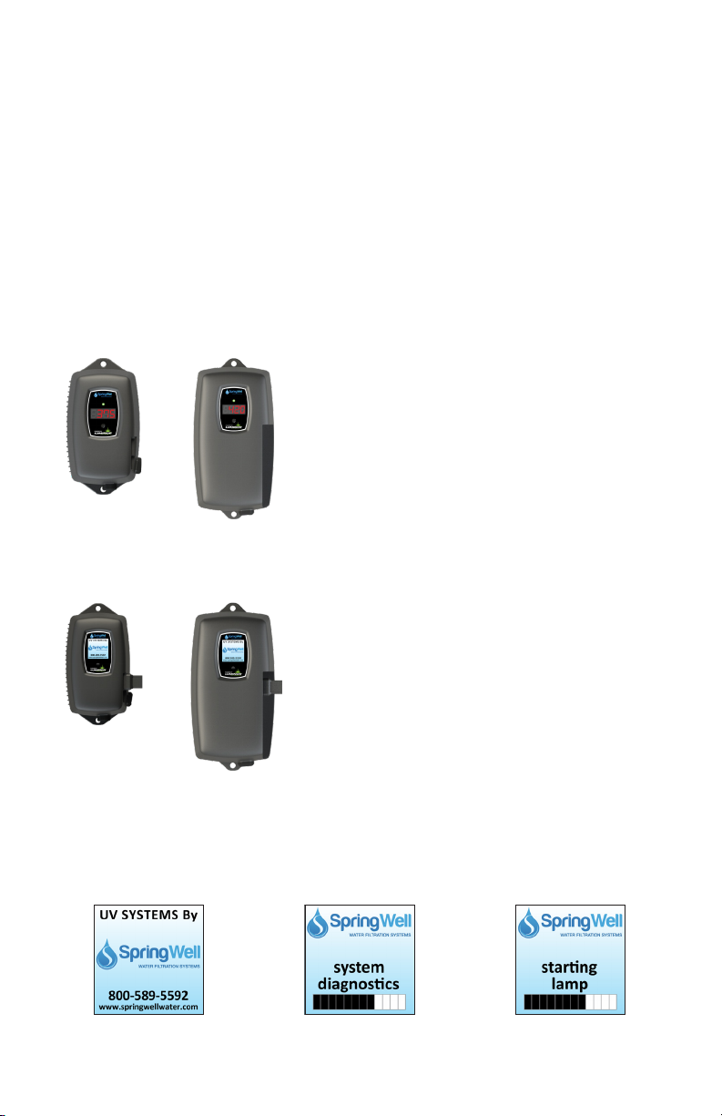
UV4 Controllers
UV4
Series
UV4-C
Series
Simplisc in operaon, these systems feature a tri-
colour LED that indicang system status and a 4-digit
display to indicate lamp life remaining. Pressing the
buon will change the display to indicate total running
me. When the UV lamp is on and within its operang
age, the LED will be green. When the UV lamp is not on
or the lamp life has expired, the LED will be illuminated
red and an audible buzzer will be sounding. To remedy
this condion, the UV lamp must be replaced with a
new genuine SpringWell UV lamp.
UV5 & UV6 Controllers
UV5/6
Series
UV5/6-C
Series
A full colour LCD screen provides the user with a
detailed descripon of the system’s performance in
addion to providing any applicable fault messages
and system diagnoscs. The controllers used in both
the UV5 and UV6 are idencal. The dierence is that
the UV6 series of products includes a UV intensity
monitor. All UV5 and UV6 controllers include an
“innite expandability port” located on the right side
of the controller. Simply plug in an oponal UV sensor
module into the expandability port of a UV5 controller
and the system will now monitor the UV intensity of
the system!
UV5 and UV6 Power-up Sequence
On start up, the controller will run through a diagnosc start-up and the sequence will be
displayed as follows on the colour LCD:

14|Page
Next, the controller checks for and inializes any oponal modules that may be aached to the system.
Oponal Modules Check
- UV Sensor
- Solenoid
- 4-20 mA
- WIFI
- Remote Alarm
- Flow Meter
OR
A nal module screen is displayed showing which specic modules were inialized.
The controller then displays the lamp opmizaon screen for 60 seconds to allow the lamp to
reach its opmum output. Finally, a nal “start-up complete” screen is displayed. The system will
now be ready to disinfect water ow.
all detected modules lamp reaching max output successful start-up
UV5 Operaonal Screens
On systems without the UV monitor, the default screen shows the Home Screen. At any point
during operaon the user is able to scroll through the Home Screen, Lamp life remaining, QR
Code, Contact Info and Maintenance Parts screens by pressing the buon located on the front
of the controller.
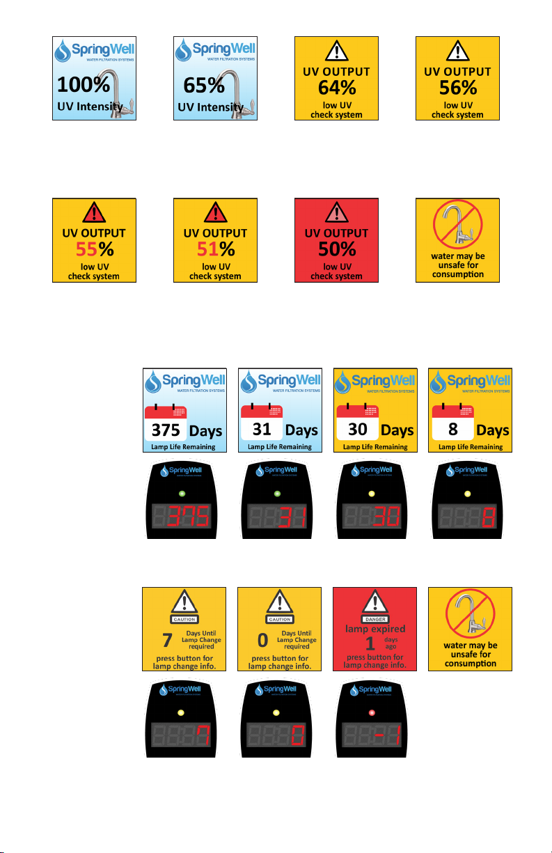
UV6 Operaonal Screens
On systems with the UV monitor, the system will display the same screens as on the UV5 except the
UV Intensity replaces the home screen. The UV Intensity screen displays the level of UV light detected
by the sensor. UV intensity can be aected by poor water quality, scaling on the quartz sleeve and/or
sensor, lamp failure or lamp expiring. The following screens show the UV Intensity dropping.
15|Page
Below 56%, the numbers and warning sign turn red and an audible chirp is given by the ballast
every 15 seconds. Below 51%, the screen is solid red and a constant audible alarm is given. This
alternates with a screen indicang “water may be unsafe for consumpon”. With the solenoid
module, the controller de-acvates the solenoid valve, shung o all water ow.
audible chirp every
15 seconds
audible chirp every
15 seconds
constant audible
alarm
cycles with red low
UV screen
Lamp Countdown Sequence
The system counts down the number of days unl a lamp change is required.
UV5
UV6
UV4
At thirty days remaining, the LED or display screen will change to a yellow cauon indicator. At
seven days remaining, the system will addionally repeat an audible chirp. Past the zero day
threshold, the LED or display screen changes to solid red with a connuous buzzer.
UV5
UV6
UV4
At any point during this sequence, the audible chirp or alarm can be deferred for seven days
by holding the controller buon down for a period of ve seconds. The number of deferrals

16|Page
used will be displayed as below. Once the deferral expires, the alarm will sound once again. The
deferral can be repeated up to three mes. PLEASE NOTE: At any point aer lamp expiraon,
the water may be unsafe for consumpon and should not be consumed without another form
of disinfecon.
System Service Suggested
UV5 & UV6 controllers will display the System Service Suggested Screen
every 6 months to remind consumers to maintain both their UV and other
preltraon. This will serve as a prompt only and will not put the system
into alarm. To clear this condion simply press the buon located below
the screen.
Lamp Replacement (UV4 systems)
Aer the lamp is expired, it must be replaced with the same part number as indicated by the
label on the reactor. Begin replacing the lamp by unplugging the power for the controller, then
refer to Installaon (page 11) for instrucons on installing the new lamp. To reset the mer in
the controller, rmly hold down the buon on the controller for 10 seconds. The controller will
read “rSt3”, “rSt2”, “rSt1” and then beep. The buon can now be released, the lamp countdown
mer has been reset.
Lamp Replacement (UV5 & UV6 systems)
Aer the lamp is expired, it must be replaced with the same part number as indicated on the
Maintenance Parts screen or on the label on the reactor. With the system powered down,
remove and discard the lamp key from the controller. The replacement lamp is packaged with
a lamp key on the connector at the end of the lamp. Remove the key from the lamp and place
it in the controller. Refer to Installaon (page 11) for instrucons on installing the new lamp.
QR Codes (UV5 & UV6 systems)
QR codes store a link to a specic page on our website. Users with a camera
phone equipped with the correct reader applicaon can scan the image
of the QR code and over a wireless network connect to a SpringWell web
page in the phone’s browser. The QR webpage has informaon on how to
purchase replacement components as well as a helpful video directory on
system servicing (i.e. How to change a UV lamp or quartz sleeve). To access
the QR code on the controller, press the control buon unl the QR code
screen appears.
17|Page
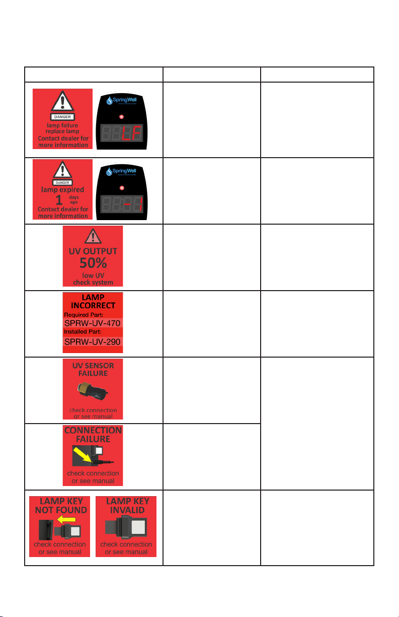
System Troubleshoong
Hard Alarms: The following give a constant audible alarm. If present, the solenoid valve is closed,
and the 4-20, remote alarm and WiFi modules transmit the alarm.
System Display Problem Resoluon
The system has detected
a problem with the
lamp.
Reset lamp protecon circuit
-unplug unit for 10 seconds.
Replace the lamp with the
part as indicated on the
silver label on the reactor or
on the Maintenance parts
screen.
Although the lamp is
powered and visibly
illuminated, due to the
lamp’s age its UV output
is no longer sucient for
proper disinfecon.
Replace the lamp with the
part as indicated on the
silver label on the reactor or
on the Maintenance parts
screen.
Low UV Intensity.
Remove and clean the
quartz sleeve and sensor.
Check water quality meets
requirements on page 5 and
add ltraon as required.
Replace lamp.
Wrong lamp or sensor
installed.
Replace component with
proper model as indicated.
The UV sensor is no
longer communicang
with the system.
Ensure all modules are
connected properly to the
system and to each other.
Modules can be tested
individually by plugging in
one at a me and cycling
power to the system.
Replace any module that is
not detected when plugged
directly into the controller.
A bad connecon has
been detected in the IEP
port.
Missing or incorrect
lamp key.
Ensure the lamp key
(packed with the lamp, on
the connector) is installed.
Unplug and reinstall the
key. Ensure the key part
number matches Lamp on
Maintenance Parts screen.

18|Page
So Alarms: The following remaining errors give a 15 second audible chirp only
System Display Problem Resoluon
The module indicated is
no longer communicat-
ing to with the system.
Ensure all modules are
connected properly to the
system and to each other.
Modules can be tested
individually by plugging in
one at a me and cycling
power to the system.
Replace any module that is
not detected when plugged
directly into the controller.
Refer to ow meter manual for detailed
troubleshoong
Warning: Aer any hard alarm, the home or facility should be disinfected. Follow the steps
under the “System Disinfecon” heading.
Temperature Management Devices
Your UV system is designed to run connuously to ensure opmal disinfecon. However, during
periods when no water is drawn through the system, the energy from the disinfecon process
can cause the temperature of the water inside the chamber to rise. In extreme situaons
elevated water temperature or the uctuaon in temperature can lower the output of the UV
lamp. In these cases, or if the elevated water temperature is a nuisance, SpringWell recommends
one of the following forms of temperature management devices.
Cooling Fan - Designed for use on High Output systems, the fan runs connuously to
cool the water by forced convecon. The long-life fan is powered independently
using a compact modular power adapter that operates from 90-265V (47-63Hz).
Order PN SPRW-130014.
Temperature Relief Valve (TRV) - On reaching a higher temperature, the TRV is
designed to drain a small amount of water to allow fresh, cooler water to enter the
system. The TRV works without power and comes complete with 10’ of drain line.
Order PN SPRW-UV-TRV05 for 1/2” ports, PN SPRW-UV-TRV07 for 3/4” ports, PN
SPRW-UV-TRV10 for 1” ports and PN SPRW-UV-TRV15 for 1 1/2” ports.
Boil Water Advisory: If any failure occurs on a UV system, the water must not be used for
human consumpon unl the system is returned to a safe operaonal mode. If the water
is used for human consumpon during this period, the water must be boiled (minimum 20
minutes at a full boil) prior to consumpon.
19|Page
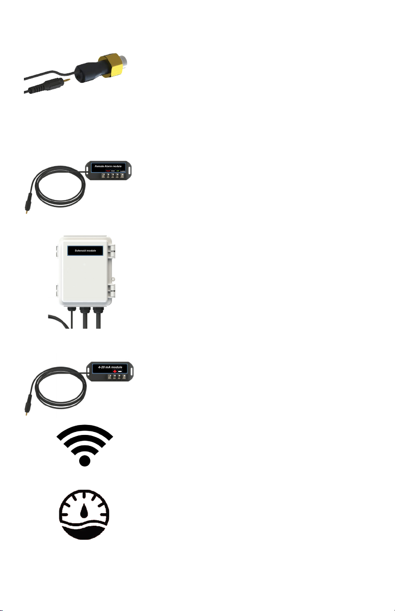
Expansion Modules
Controllers incorporate an “Innite Expandability Port” (IEP)
which allows for expansion to the UV sensor and all other
modules. Each module (including the sensor) comes with
both a male and female connecon. Connect any device to
the controller and all subsequent devices are then connected
into the female end of last device added in a “daisy chain”
conguraon.
The following oponal expansion modules are available for use on UV5 & UV6 UV controllers.
Contact your authorized distributor for purchasing informaon.
REMOTE ALARM CONNECTION MODULE: Allows for a
connecon to a remote device such as a buzzer, light, alarm
system, PLC, etc., via a pair of contacts. In normal operaon
the OK and COM contacts will be connected, and in a fault
condion (Low UV, Lamp fail, Power Fail), the Fault and COM
contacts will be connected. Maximum contact rang is 30V / 1A
(use 16-22 AWG). Order PN SPRW-MOD-RAM.
SOLENOID CONNECTION MODULE: Connects a NORMALLY
CLOSED line voltage solenoid valve to the controller. Maximum
contact rang is 240VAC (50-60Hz) / 30VDC / 2A. On a non-
monitored system, the solenoid will only close on a lamp failure
error. On a monitored system, the solenoid is closed when
the UV level drops below 50%. Also note that in cases where
emergency use of untreated water is required, the controller
can be placed into a manual override mode allowing for the
ow of water in an alarm condion. Order PN SPRW-MOD-
SOL1.
4-20 mA MODULE: Outputs a 4-20mA signal of the UV output
to a remote device such as a data logger or computer. Order PN
SPRW-MOD-420.
The WiFi module and accompanying IoT applicaon allows you
to connect your UV system to a smart phone, tablet, computer
or other connected plaorm. View system status, receive SMS
or email messages of alarm condions and monitor the health
of your UV from anywhere via this connected plaorm. Connect
the device via the APP found on Google Play or the APP Store
and connect your UV device to your router, then download the
soware for your connected device. Order PN MOD-APP.
The Ultrasonic Flow Meter enables your UV system to dim
power in mes of low to no ow, saving you money on energy,
reducing water temperature, and decreasing the risk of fouling.
20|Page
Standard Output Systems
EQUIPMENT SPECIFICATIONS
Mul-Use / Residenal systems
MODEL
SPRW-UV4-2
SPRW-UV5-2
SPRW-UV6-2
SPRW-UV4-3
SPRW-UV5-3
SPRW-UV6-3
SPRW-UV4-6
SPRW-UV5-6
SPRW-UV6-6
SPRW-UV4-11
SPRW-UV5-11
SPRW-UV6-11
SPRW-UV4-15
SPRW-UV5-15
SPRW-UV6-15
SPRW-UV4-21
SPRW-UV5-21
SPRW-UV6-21
Flow Rate
30mJ/cm
2
@ 95% UVT
2 gpm 3 gpm 6 gpm 11 gpm 15 gpm 21 gpm
7.6 lpm 11.4 lpm 22.7 lpm 41 lpm 56.8 lpm 79 lpm
0.45 m
3
/hr 0.70 m
3
/hr 1.4 m
3
/hr 2.5 m
3
/hr 3.4 m
3
/hr 4.8 m
3
/hr
Flow Rate
16mJ/cm
2
@ 95% UVT
4 gpm 6 gpm 11 gpm 20 gpm 30 gpm 39 gpm
15.1 lpm 23 lpm 41 lpm 77 lpm 113.6 lpm 150 lpm
0.87 m
3
/hr 1.4 m
3
/hr 2.5 m
3
/hr 4.6 m
3
/hr 6.8 m
3
/hr 8.9 m
3
/hr
Flow Rate
40mJ/cm
2
@ 95% UVT
1.6 gpm 2.4 gpm 4.4 gpm 8.3 gpm 12 gpm 16 gpm
6.1 lpm 9.1 lpm 17 lpm 31 lpm 45.4 lpm 59 lpm
0.36 m
3
/hr 0.50 m
3
/hr 1.0 m
3
/hr 1.9 m
3
/hr 2.7 m
3
/hr 3.6 m
3
/hr
Port Size ½”FNPT ½”MNPT ¾”MNPT ¾”MNPT 1”MNPT 1”MNPT
Electrical 90-265V/50-60Hz. 1A Max.
Plug Type American: NEMA 5-15P
Lamp Power (Was) 8 15 22 39 50 42
Power (Was) 14 20 30 49 62 51
Replacement Lamp SPRW-UV-210 SPRW-UV-290 SPRW-UV-470 SPRW-UV-820 SPRW-UV-999 SPRW-UV-850
Replacement Sleeve SPRW-UV-
Q210
SPRW-UV-
Q290
SPRW-UV-
Q470
SPRW-UV-
Q820
SPRW-UV-
Q999
SPRW-UV-
Q850
Reactor
Dimensions
6.4 x 26.2 cm
(2.5 x 10.3”)
6.4 x 36.4 cm
(2.5 x 14.3”)
6.4 x 54.2 cm
(2.5 x 21.3”)
6.4 x 89.5 cm
(2.5 x 35.2”)
6.4 x 101.6 cm
(2.5 x 40.0”)
8.9 x 91.7 cm
(3.5 x 36.1”)
Chamber Material 304 Stainless Steel, A249 Pressure Rated Tubing
Controller Dimensions 171.5 x 92.1 x 101.6 mm (6.8 x 3.6 x 4”)
Operang Pressure 0.7-10.3 bar (10-150 psi)
Operang Water Temperature 2-40° C (36-104° F)
UV Monitor YES on all “UV6” models. Upgrade available for “UV5” models (NOT available on UV4 models)
Solenoid Output YES (oponal solenoid module (SPRW-MOD-SOL1) sold separately)
Dry Contacts YES (remote alarm module (SPRW-MOD-RAM) sold separately)
4-20mA Output YES (4-20mA module (SPRW-MOD-420) sold separately)
Temperature Mgmt. Valve NA SPRW-UV-
TRV05 SPRW-UV-TRV07 SPRW-UV-TRV10
Cooling Fan NO
OPTIONAL
(SPRW-
130014)
Lamp Change Reminder YES
Lamp Out Indicator YES
Shipping Weight 2.9 kg
(6.3 lbs)
3.6 kg
(7.9 lbs)
4.4 kg
(9.6 lbs)
6.0 kg
(13.2 lbs)
6.5 kg
(14.4 lbs)
8.2 kg
(18.0 lbs)
This manual suits for next models
32
Table of contents
Popular Accessories manuals by other brands


Rittal
Rittal SK 3185830 Assembly and operating instructions

Milanity
Milanity SLEV05 user manual

PCB Piezotronics
PCB Piezotronics 354C10/NC Installation and operating manual

Thermo Scientific
Thermo Scientific 3554-35A Operator's manual and parts list

Siemens
Siemens SITRANS LG240 operating instructions

Triumph
Triumph 45-6090W instruction manual