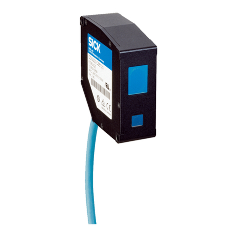
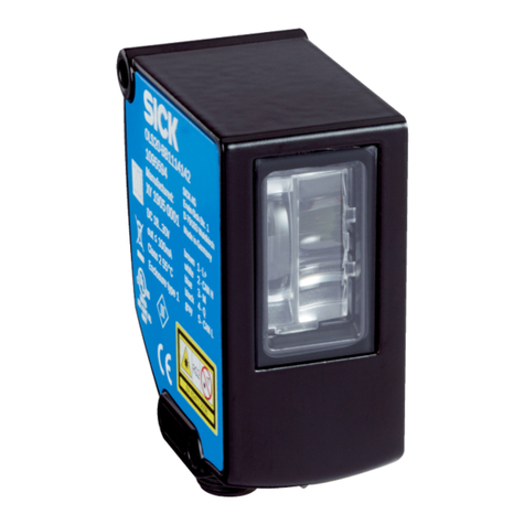
SICK PS30 User manual

EN
PS30
Pattern sensors
OPERATING INSTRUCTIONS

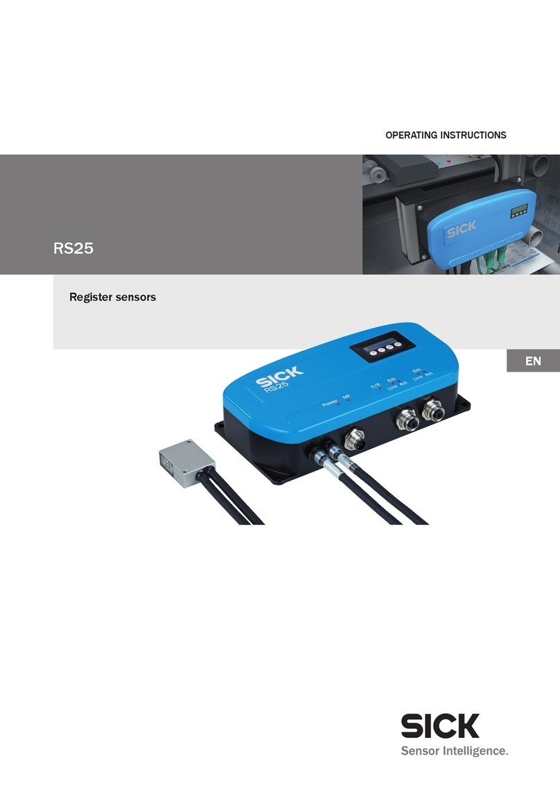
Operating instructions Pattern sensors PS30
2 © SICK AG • Advanced Industrial Sensors • Subject to change without notice • 8018916
Copyright protection!
This work is protected by copyright. The associated rights
are reserved by SICK AG. Reproduction of this document
is only permissible within the bounds of the statutory
regulations of copyright law. Alteration or abridgment
of the document is not permitted without the explicit
written approval of SICK AG.
Only NFPA79 applications.
Adapters including field wiring
cable are available.
See product information.
Enclosure Type 1.

© SICK AG • Advanced Industrial Sensors • Subject to change without notice • 8018916 3
Operating instructions Pattern sensors PS30
Table of contents
Table of contents
1 General information........................................................................... 7
1.1 Information on the operating instructions ...............................7
1.2 Explanation of symbols .............................................................8
1.3 Limitation of liability ..................................................................9
1.4 Scope of delivery .......................................................................9
1.5 Customer service.......................................................................9
1.6 EU declaration of conformity.................................................. 10
1.7 Environmental protection....................................................... 10
2 Safety ................................................................................................ 11
2.1 Intended use ........................................................................... 11
2.2 Incorrect use ........................................................................... 11
2.3 Modicationsandconversions .............................................. 11
2.4 Requirements for skilled persons and operating
personnel ................................................................................ 12
2.5 Operational safety and particular hazards ........................... 12
2.6 Hazard warnings and operational safety .............................. 12
3 Identication .................................................................................... 13
3.1 Type label ................................................................................ 13
4 Setup and function .......................................................................... 14
4.1 Design ..................................................................................... 14
4.2 Function................................................................................... 14
4.3 Operating modes ................................................................... 15
4.3.1 Endless material operating mode........................... 15
4.3.2 Single object operating mode ................................. 16
4.4 Display and operating elements............................................ 16
4.5 Display ..................................................................................... 18
4.6 Bar graph................................................................................. 18
5 Transport and storage ..................................................................... 19
5.1 Transport ................................................................................. 19
5.2 Transport inspection............................................................... 19
5.3 Storage .................................................................................... 20

Operating instructions Pattern sensors PS30
Table of contents
4 © SICK AG • Advanced Industrial Sensors • Subject to change without notice • 8018916
6 Mounting .......................................................................................... 21
6.1 Mounting procedure ............................................................... 21
6.2 Requirements at the mounting site....................................... 21
7 Electrical connection....................................................................... 23
7.1 Safety....................................................................................... 23
7.2 Wiring notes ............................................................................ 23
7.3 System construction............................................................... 26
7.4 Connecting the pattern sensor electrically ........................... 26
7.5 Connection diagrams ............................................................. 27
7.5.1 Connection example, supply voltage and
encoder signals........................................................ 27
7.5.2 Ethernet connection diagram ................................. 28
8 Commissioning................................................................................. 29
8.1 Steps to take ........................................................................... 29
8.2 Setting up the encoder........................................................... 30
9 Operating the sensor ....................................................................... 33
9.1 Navigation ............................................................................... 33
9.2 Selecting an option................................................................. 33
9.3 Changing the value................................................................. 34
9.4 Setting menu........................................................................... 34
9.4.1 Parameter operating mode ..................................... 34
9.4.2 Encoder type (EncTyp) parameter .......................... 35
9.4.3 Encoder resolution (EncRes) parameter ................ 35
9.4.4 Encoder direction (EncDir) parameter.................... 35
9.4.5 External teach-in parameter (ETeach) .................... 35
9.4.6 Ethernetconguration(Ethern)parameter............ 38
9.4.7 Device reset (Reset) parameter .............................. 39
9.5 Teach menu............................................................................. 40
9.5.1 Manual start-length teach-in parameter via
control panel (StaLen) ............................................. 40
9.5.2 Switching point shift parameter (OffSet)................ 41
9.5.3 Blanking areas (Blank) parameter.......................... 43
9.5.4 Specifying image areas via “AT” external signal .... 45
9.6 Monitoring menu .................................................................... 46
9.7 Info menu ................................................................................ 47

© SICK AG • Advanced Industrial Sensors • Subject to change without notice • 8018916 5
Operating instructions Pattern sensors PS30
Table of contents
10 Operation via Ethernet TCP/IP ....................................................... 48
11 Operation via SOPASair .................................................................. 49
11.1 Integrating PS30 pattern sensor in the network .................. 49
11.2 Monitoring menu ................................................................... 50
11.3 Teach-in menu ....................................................................... 51
11.4 Settings menu......................................................................... 53
11.5 Device info menu.................................................................... 55
11.6 Settings (of SOPASair WebUI) menu...................................... 56
12 Cleaning and maintenance ............................................................. 57
12.1 Cleaning .................................................................................. 57
12.2 Maintenance ........................................................................... 57
13 Troubleshooting ............................................................................... 58
13.1 Possible error indicators ........................................................ 58
13.2 Troubleshooting guide ............................................................ 59
13.2.1 Errors caused by the combination pattern
sensor – encoder..................................................... 59
13.2.2 Errors caused by mounting or teaching-in ............. 61
13.2.3 Errors caused by the system................................... 62
13.2.4 Errors caused by the network connection
and SOPASair ........................................................... 63
13.3 Returns.................................................................................... 64
13.4 Disposal................................................................................... 64
14 Repairs.............................................................................................. 65
15 Technical data.................................................................................. 66
15.1 Dimensions ............................................................................. 66
15.2 Optics/Features ...................................................................... 67
15.3 Supply...................................................................................... 67
15.4 Inputs....................................................................................... 67
15.5 Outputs.................................................................................... 68
15.6 Interfaces ................................................................................ 68
15.7 Encoder ................................................................................... 68
15.8 Ambient conditions................................................................. 68
15.9 Structural design .................................................................... 69

Operating instructions Pattern sensors PS30
Table of contents
6 © SICK AG • Advanced Industrial Sensors • Subject to change without notice • 8018916
16 Accessories ...................................................................................... 70
16.1 Connection technology........................................................... 70
16.1.1 Female cable connectors with cables .................... 70
16.1.2 Connection cable ..................................................... 70
16.1.3 Ethernet cables........................................................ 70
16.2 Mounting systems .................................................................. 71
16.2.1 Universal clamp plate .............................................. 71
16.2.2 Mounting rods .......................................................... 71
17 Licenses............................................................................................ 73
18 Menu structure................................................................................. 74
18.1 “Setup” menu ......................................................................... 74
18.2 “Monitr” menu ........................................................................ 74
18.3 “Teach” menu ......................................................................... 74
18.4 “Setting” menu ....................................................................... 75
18.5 “Info” menu............................................................................. 75
Index .......................................................................................................... 76

© SICK AG • Advanced Industrial Sensors • Subject to change without notice • 8018916 7
Operating instructions Pattern sensors PS30
General information
1 General information
1.1 Information on the operating instructions
These operating instructions provide important information on how to
handlePS30patternsensorsfromSICKAG.Adherencetoallthespecied
safety notes and guidelines is a prerequisite for working safely.
You must also comply with any local work safety regulations and general
safetyspecicationsapplicabletotheuseofthepatternsensors.
Ensure that you read through these operating instructions carefully before
starting any work. They constitute an integral part of the product and
should be stored in the direct vicinity of the pattern sensors so they remain
accessible to personnel at all times.
Should the pattern sensor be passed on to a third party, these operating
instructions should be handed over with it.
NOTE!
A machine cycle as the input signal, e.g. via an encoder
or a motor feedback system, is necessary for the opera-
tion of the pattern sensor.

Operating instructions Pattern sensors PS30
General information
8 © SICK AG • Advanced Industrial Sensors • Subject to change without notice • 8018916
1.2 Explanation of symbols
Warnings Warnings in these operating instructions are labeled with symbols. The
warnings are introduced by signal words that indicate the extent of the
danger.
These warnings must be observed at all times and care must be taken to
avoid accidents, personal injury, and material damage.
DANGER!
… indicates a situation of imminent danger, which will
lead to a fatality or serious injuries if not prevented.
WARNING
… indicates a potentially dangerous situation, which may
lead to a fatality or serious injuries if not prevented.
CAUTION!
… indicates a potentially dangerous situation, which may
lead to minor/slight injuries if not prevented.
WARNING!
… indicates a possible hazardous situation which may
lead to physical damage if it is not avoided.
Tips and recommendations
NOTE!
… highlights useful tips and recommendations as well as
information for efcient and trouble-free operation.

© SICK AG • Advanced Industrial Sensors • Subject to change without notice • 8018916 9
Operating instructions Pattern sensors PS30
General information
1.3 Limitation of liability
Applicable standards and regulations, the latest state of technological de-
velopment, and our many years of knowledge and experience have all been
taken into account when assembling the data and information contained in
these operating instructions.
The manufacturer accepts no liability for damage caused by:
• Failing to observe the operating instructions
• Incorrect use
• Use by untrained personnel
• Unauthorized conversions
• Technicalmodications
• Use of unauthorized spare parts/consumable parts.
With special variants, where optional extras have been ordered, or owing to
the latest technical changes, the actual scope of delivery may vary from the
features and illustrations shown here.
1.4 Scope of delivery
Included with delivery:
• PS30 pattern sensor
• Blind plug for M12 Ethernet connection
• Adjustment tool
• Optional: Accessories (→page 70, chapter 16).
Documentation enclosed for each pattern sensor:
• Quickstart
1.5 Customer service
If you require any technical information, our customer service department
will be happy to help.
See the back page for your agency.
NOTE!
Before calling, make a note of the type designation, serial
number, and software version to enable faster process-
ing. You can nd the type designation and serial number
on the type label. →See page 13, Fig. 1.
The software version can be read out via the “SWVers”
parameter on the sensor. →See page 47, 9.7.

Operating instructions Pattern sensors PS30
General information
10 © SICK AG • Advanced Industrial Sensors • Subject to change without notice • 8018916
1.6 EU declaration of conformity
→ You can download the EU declaration of conformity online from
“www.sick.com/PS30”.
1.7 Environmental protection
→ See page 64, chapter 13.4 “Disposal”.

© SICK AG • Advanced Industrial Sensors • Subject to change without notice • 8018916 11
Operating instructions Pattern sensors PS30
Safety
2 Safety
2.1 Intended use
The PS30 pattern sensor is an opto-electronic sensor intended for non-con-
tact recognition of recurring patterns. A machine cycle as the input signal,
e.g. via an encoder or a motor feedback system, is necessary for the opera-
tion of the pattern sensor.
SICK AG assumes no liability for losses or damage arising from the use of
the product, either directly or indirectly. This applies in particular to use of
the product that does not conform to its intended purpose and is neither
described nor mentioned in this documentation.
2.2 Incorrect use
The PS30 pattern sensor does not constitute a safety component accord-
ing to the EC Machinery Directive (2006/42/EC).
The pattern sensors must not be used in explosion-hazardous areas.
Any other use that is not described as intended use is prohibited.
Never install or connect accessories if their quantity and composition are
notclearlyspecied,oriftheyhavenotbeenapprovedbySICKAG.
WARNING
Danger due to improper use!
Any improper use can result in dangerous situations.
For this reason:
• Pattern sensors should be used only according to
intendedusespecications.
• All information in these operating instructions must be
strictly observed.
2.3 Modicationsandconversions
Modicationsandconversionstothepatternsensorand/ortheinstallation
may result in unforeseeable dangers.
Beforeanytechnicalmodicationstoandexpansionsofthepatternsensor,
the prior written approval of the manufacturer must be obtained.

Operating instructions Pattern sensors PS30
Safety
12 © SICK AG • Advanced Industrial Sensors • Subject to change without notice • 8018916
2.4 Requirements for skilled persons and operating personnel
WARNING
Riskofinjuryduetoinsucienttraining.
Improper handling may result in considerable personal
injury and material damage.
For this reason:
• All work must only ever be carried out by the stipulated
persons.
Theoperatinginstructionsstatethefollowingqualicationrequirementsfor
the various areas of work:
• Instructed personnel
Duringabriengbytheoperator,suchpersonshavebeeninstructed
about tasks assigned to them and about potential dangers in the event
of improper action.
• Qualied personnel
are able to carry out the work assigned to them and independently
recognize potential risks due to their specialist training, knowledge, and
experience, as well as knowledge of the relevant regulations.
• Electrical specialists
are able to carry out work on electrical systems and independently
recognize potential risks due to their specialist training, knowledge, and
experience, as well as knowledge of the relevant standards and regula-
tions.
InGermany,electricalspecialistsmustmeetthespecicationsofthe
work safety regulation BGV A3 (e.g., master electrician). Other relevant
regulations applicable in other countries must be observed.
2.5 Operational safety and particular hazards
Please observe the safety notes and the warnings listed here and in other
chapters of these operating instructions to reduce the possibility of risks to
health and avoid dangerous situations.
2.6 Hazard warnings and operational safety
Light sender The PS30 pattern sensor is equipped with LED illumination. The sensor
meets the criteria of risk group 1 according to IEC 62471:2006.
No special measures are required.

© SICK AG • Advanced Industrial Sensors • Subject to change without notice • 8018916 13
Operating instructions Pattern sensors PS30
Identication
3 Identication
3.1 Type label
The type label is located on the back of the pattern sensor.
1
23 54
Fig. 1: Type label
1 Type designation
2 Material number
3 MAC address
4 Serial number
5 Machine-readable code

Operating instructions Pattern sensors PS30
Setup and function
14 © SICK AG • Advanced Industrial Sensors • Subject to change without notice • 8018916
4 Setup and function
4.1 Design
1
2
2
5
3
4
1
2
2
5
3
4
Fig. 2: “PS30 pattern sensor” design
1 Center of the optical axis
2 Fixing hole
3 M12 male connector, 12-pin/M12 female connector, 4-pin, rotatable
→ See page 27, chapter 7.5.
4 Function indicators
5 Display and control unit
4.2 Function
Field of
view
Light spo
t
Fig. 3: Recorded image from the perspective of the “PS30 pattern sensor”
Vertical bars:
Cuts of the individual lines, corresponds to the encoder resolution
(→ See page 68, chapter 15.7).
Blue square marks:
Clear and contrast-rich pattern areas automatically selected by the sensor. Five
areas are shown here as examples.

© SICK AG • Advanced Industrial Sensors • Subject to change without notice • 8018916 15
Operating instructions Pattern sensors PS30
Setup and function
The PS30 pattern sensor is an opto-electronic sensor which detects recur-
ring patterns without making contact.
The principle of operation is based on a line sensor which constantly
searches for contrast differences and sharp edges in the print image (see
gure3).Theseclearareassignicantinthepatternareautomatically
selected by the sensor during the teach-in process. The points are in
exactly the same spot in the same image and contrast pattern. The sensor
evaluates grayscale.
A taught-in image is used as a reference for the subsequent detection of
a recurring contrast pattern. The print marks usually used for determining
positionarenolongernecessary.Theidenticationofapatternmatching
the reference pattern initiates a switching output.
Information about the speed of the material, e.g. from encoder pulses or
a motor feedback system, is necessary for operation of the PS30 pattern
sensor.
4.3 Operating modes
The PS30 pattern sensor can be operated in two operating modes:
a) Endless material
b) Single object.
4.3.1 Endless material operating mode
Exactdeterminationofpositionfordening,forinstance,thecutpositions
isnecessaryforfurtherprocessingofendlessmaterialssuchaslmand
paper webs, for example for creating labels and packaging with constant
repeat length. Typically, the target cut position is selected as the start point
of the reference image which is completed before the end of the repeat
length. The start point of the teach-in area is the position of the switching
signal.Shiftingoftheswitchingpointcanalsobecongured.
Signal
Teach Start
Signal
Teach Stop
Single object
Endless material Teach Start
Teach Stop
Signal Signal
Offset
Signal
Offset
Signal
Fig. 4: Endless operating mode

Operating instructions Pattern sensors PS30
Setup and function
16 © SICK AG • Advanced Industrial Sensors • Subject to change without notice • 8018916
4.3.2 Single object operating mode
The position is to be determined by separate, repeating objects with
identicalpatternsbutnotwithxeddistances.Anobjectorasectionof
the object is taught in as a reference. The end of the teach-in area is used
as the position for output of the switching signal. Shifting of the switching
pointcanbedened.
Signal
Teach Start
Signal
Teach Stop
Single object
Endless material Teach Start
Teach Stop
Signal Signal
Offset
Signal
Offset
Signal
Fig. 5: Single object operating mode
4.4 Display and operating elements
1
3564
EscSet
2
Fig. 6: Display and operating elements
1 Display
2 Pushbuttons
3 Function indicator (yellow) “Act”
4 Function indicator (green) “Link”
5 Function indicator (yellow) “Q”
6 Function indicator (green) “ON”

© SICK AG • Advanced Industrial Sensors • Subject to change without notice • 8018916 17
Operating instructions Pattern sensors PS30
Setup and function
Function indicators (LEDs) Function indicator Description
Act Data transfer display
• LED yellow: data transfer
• LED off: no data transfer
Link Ethernet connection display
• Green LED: Ethernet connection available
• LED off: No Ethernet connection available
QSwitching output display
• LED yellow: output high
• LED off: output low
• LEDashes(10Hz):overcurrent/undercurrent/short-cir-
cuit protection has triggered
ON Operating status display
• Green LED:
normal operation/supply voltage on
• LED off: no operation
Table 1: Function indicators (LEDs)
Operating menu symbols The operating menu differentiates between the symbols “RUN”, “MEN” and
“SET”.
Icon Description
RUN If the “RUN” signal lights up in the display, the current
operating data of the sensor is displayed.
MEN The MEN symbol lights up when the device is in the menu
and the last selection level has not yet been reached.
SET If the “SET” symbol light up, the settings of the sensor can
be changed and, for example, values can be set.
Table 2: Operating menu symbols
Pushbuttons Pushbutton Description
• Select operating menu, parameter, or option.
• Reduce value.
• Select operating menu, parameter, or option.
• Increase value.
• Short press:
– Switch to the next-lowest menu level.
– Save parameter change.
– Conrmselection.
• Long pressing time (> 2 sec.):
– Operating menu start.
• Short press: Exit parameters without saving. Switch to
the next-highest menu level.
• Long press: Exit parameters without saving. Change to
the default display - Quality of Run.
Table 3: Pushbuttons

Operating instructions Pattern sensors PS30
Setup and function
18 © SICK AG • Advanced Industrial Sensors • Subject to change without notice • 8018916
4.5 Display
Default display The Quality of Run is displayed by default:
EscSet
RUN
Fig. 7: Default display
Operating menus - 4 x ,
Monitoring/Setting/Teach-in/Info
EscSet
Teach
MEN
Fig. 8: Operating menu
Parameters using example of
monitoring
EscSet
ErrCod
MEN
Fig. 9: Parameter display
4.6 Bar graph
Teach-in quality Afterteach-inhasbeenrun,thenumberofashingbarssignalsthequality
of the teach-in process:
• 3ormorebarsashing:teach-inprocesswassuccessful.
• Fewerthan3barsashing:checkwhetherthesignalcorrectlyswitches.
If the signal does not correctly switch, repeat the teach-in process.
Process quality If the “RUN” signal lights up, the number of bars shows the process quality.
• If2barsorfewerashing:checkwhetherthesignalcorrectlyswitches.
• If the signal does not correctly switch, check the sensor for correct
installation, monitor the quality of the print image of the object or the
mechanical control of the object.
• If necessary, repeat the teach-in process.

© SICK AG • Advanced Industrial Sensors • Subject to change without notice • 8018916 19
Operating instructions Pattern sensors PS30
Transport and storage
5 Transport and storage
5.1 Transport
Improper transport
WARNING!
Damage to the pattern sensor due to improper trans-
port.
Substantial material damage may result in the event of
improper transport.
For this reason:
• The distance measuring device should be transported
only by trained specialist staff.
• The utmost care and attention is required at all times
during unloading and transportation on company
premises.
• Note the symbols on the packaging.
• Do not remove packaging until immediately before you
start mounting.
5.2 Transport inspection
Improper transport Upon receipt, please check the delivery for completeness and for any dam-
age that may have occurred in transit.
In the case of transit damage that is visible externally, proceed as follows:
• Do not accept the delivery or only do so conditionally.
• Note the scope of damage on the transport documents or on the trans-
port company's delivery note.
• File a complaint.
NOTE!
Complaints regarding defects should be led as soon as
these are detected. Damage claims are only valid before
the applicable complaint deadlines.

Operating instructions Pattern sensors PS30
Transport and storage
20 © SICK AG • Advanced Industrial Sensors • Subject to change without notice • 8018916
5.3 Storage Store the pattern sensor under the following conditions:
• Do not store outdoors.
• Store in a dry area that is protected from dust.
• Do not expose to any aggressive substances.
• Protect from sunlight.
• Avoid mechanical shocks.
• Storage temperature: between –20 and +75 °C
• Relative humidity: max. 95%, non-condensing
• For storage periods of longer than 3 months, check the general condi-
tion of all components and packaging on a regular basis.
Other manuals for PS30
1
Table of contents
Other SICK Accessories manuals

SICK
SICK CSS High Speed User manual

SICK
SICK MPS-G 1108675 User manual

SICK
SICK GLS621 User manual

SICK
SICK MLS Series User manual

SICK
SICK GRTE18S V Series User manual

SICK
SICK PowerProx WTT12L-A Series User manual

SICK
SICK LMS100 User manual

SICK
SICK TiM2 Series User manual

SICK
SICK WLD4F User manual

SICK
SICK W26 User manual

SICK
SICK WL34 User manual

SICK
SICK SureSense HSE18 Series User manual

SICK
SICK G6 Inox User manual

SICK
SICK GRTE18 User manual

SICK
SICK PowerProx Mini WTT4SLC User manual

SICK
SICK deTec4 Core User guide

SICK
SICK SIM2000 User manual

SICK
SICK GTE20 User manual

SICK
SICK GTE6 Series User manual

SICK
SICK GL6 Series User manual