SPX FLOW S280 M-14 User manual

MISSISSIPPI POWER COMPANY
KEMPER COUNTY IGCC PROJECT
CONTRACT NO.: 17352
TAG NO.: CLCW HX, SPARE UNIT
SPX MATERIAL NO.: G2010000818
APV PLATE HEAT EXCHANGERS
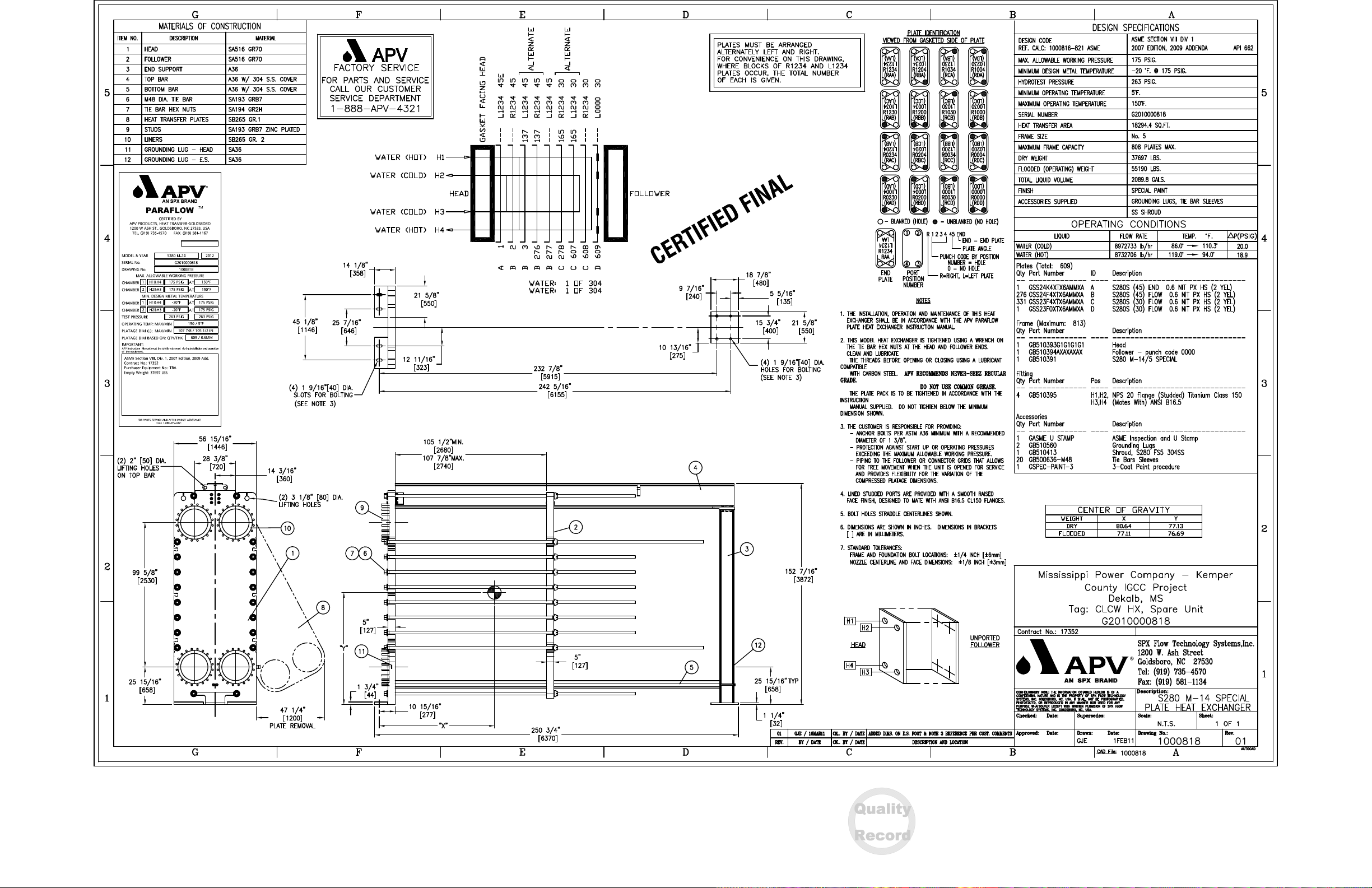
SPX/APV MODEL: S280 M-14
SPX FLOW TECHNOLOGY SYSTEMS, INC.
1200 W. ASH STREET
GOLDSBORO, NC 27530
UNITED STATES
TEL 888 . 278 . 4321
www.spxft.com
IGCC - MULTIPAGE - DOCUMENTATION PACKAGE FOR G2010000818 - TAG NO
1000818 DATABOOK Rev: NA
APV NORTH AMERICA PO: MPC17352-0001
MM218132 0 Unit 1
Southern Company Generation Kemper County
Approved

TABLE OF CONTENTS
MANUFACTURING RECORD BOOK
SECTION
1 CERTIFIED FINAL DRAWING
2 CERTIFICATE OF CONFORMANCE
3 ASME CALCULATION
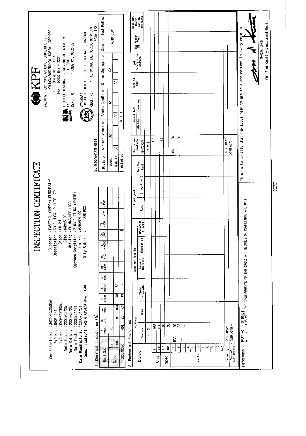
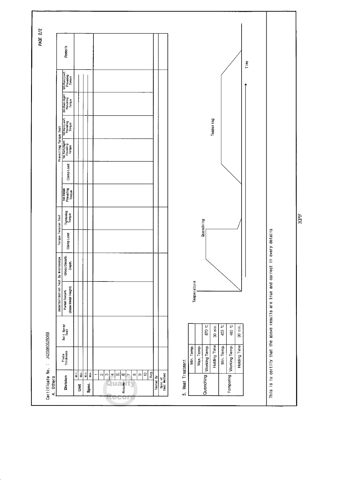
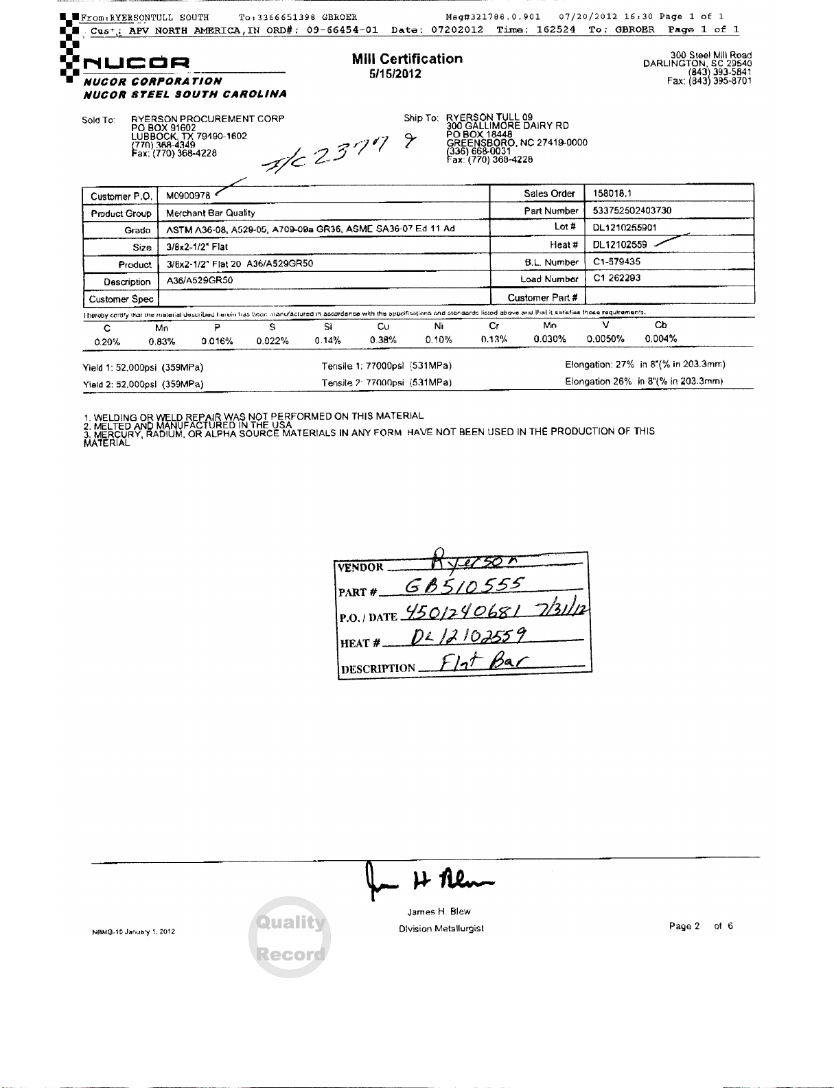
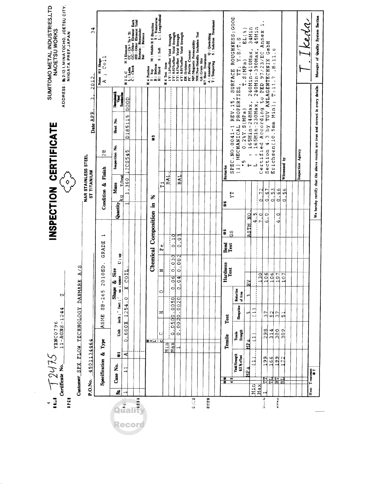
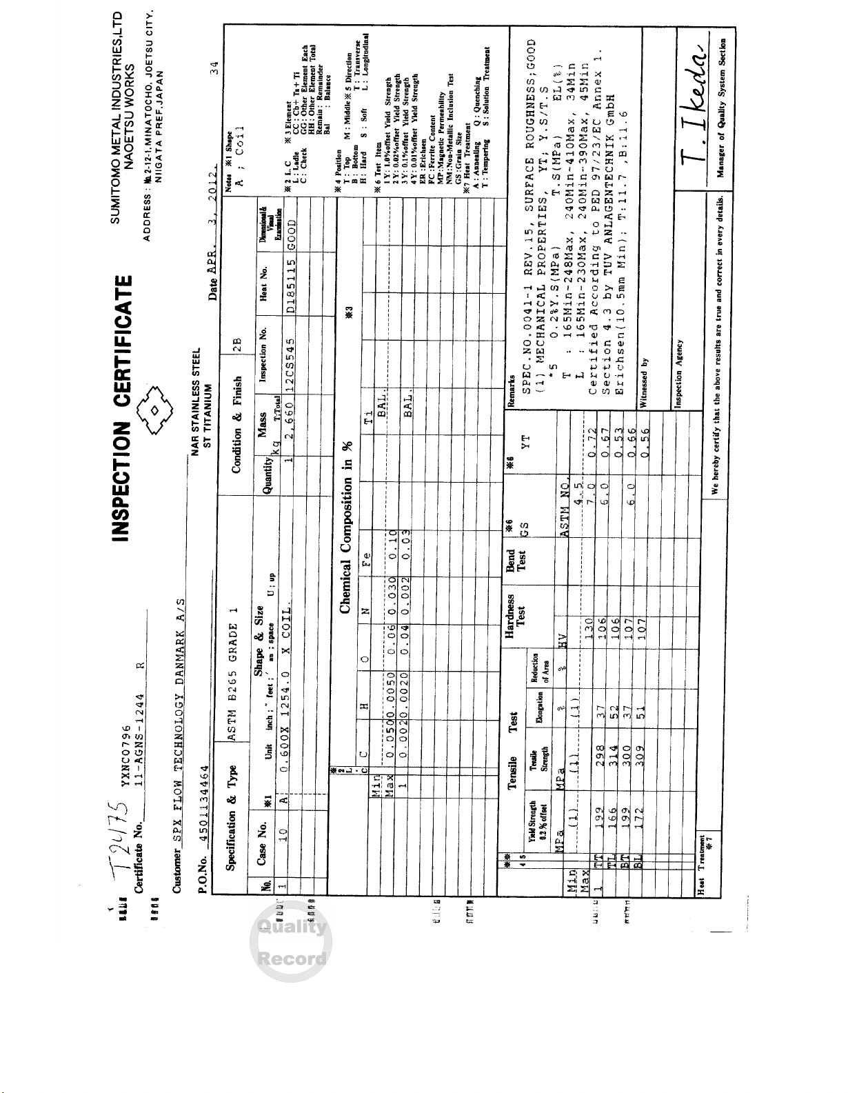
4 MATERIAL TEST REPORT
5 PAINT REPORT
6 DYE PEN REPORT
7 HYDROSTATIC PRESSURE TEST SHEET
8 ASME U-1 DATA REPORT
9 NAMEPLATE FACSIMILE
10 SIGNED INSPECTION AND TEST PLAN
11 INSTRUCTION MANUAL
SPX FLOW TECHNOLOGY SYSTEMS, INC.
1200 W. ASH STREET
GOLDSBORO, NC 27530
UNITED STATES
TEL 888 . 278 . 4321
www.spxft.com
Kemper County MM218132
Approved
Kemper County MM218132
Approved

Document Title:
APV Order Number:
Customer:
Customer Contract No.:
Certificate of Conformance
G2010000816-821
Mississippi Power Company
17352
ISSUE:
DATE:
BY:
Page
00
25Oct12
GJE
1 of1
SPX Flow Technology Systems, Inc.
PH: (919) 735-4570 FX: (919) 581-1134
Certificate Of Conformance
Customer: Mississippi Power Company
Customer Contract No:
Location:
Project:
17352
Dekalb, MS
Kemper County IGCC Project
This is to certify that the following Plate Heat Exchangers comply with
the purchase order and were built to ASME Section VIII, Division 1 2007
Edition, 2009 Addenda using approved designs and materials.
Signed & Approved: Gregory Eckard Project Manager / Mechanical Engineer
Material # Model # Tag #
G2010000816 S280 M-14 CLCW HX, Operating Unit 1
G2010000817 S280 M-14 CLCW HX, Operating Unit 2
G2010000818 S280 M-14 CLCW HX, Spare Unit
G2010000819 S280 M-14 CLCW HX, Operating Unit 3
G2010000820 S280 M-14 CLCW HX, Operating Unit 5
G2010000821 S280 M-14 CLCW HX, Operating Unit 4
Kemper County MM218132
Approved

ENGINEER: Greg Eckard
DATE:
CALC NO.: 1000816-821 ASME REV NO.: 00
HEAT EXCHANGER MODEL: S280 MGS-14
REFERENCE DRAWING NUMBER: 1000816-821
DESIGN PRESSURE: 175.00 psi
TEST PRESSURE: 263.00 psi
MAXIMUM DESIGN TEMPERATURE: 150.00 F
MINIMUM DESIGN METAL TEMPERATURE: -20.00 F
P.O. NO: 17352
TAG NO.:
CUSTOMER: Mississippi Power Company
LOCATION: Dekalb, MS
03-Feb-11
PRESSURE VESSEL CALCULATIONS
FOR AN
APV PLATE HEAT EXCHANGER
IN ACCORDANCE WITH THE
ASME BOILER AND PRESSURE VESSEL CODE
SECTION VIII, DIVISION 1
2010 EDITION
1 of 5
Kemper County MM218132
Approved

ENGINEER: Greg Eckard
DATE:
CALC NO.: 1000816-821 ASME REV NO.: 00
THE FOLLOWING PARAMETERS APPLY TO THIS HEAT EXCHANGER DESIGN:
P = 175.000 psi DESIGN PRESSURE (UG-21, Appendix 3)
A = 5104.755 sq in PRESSURE AREA
d = 47.677 inches SHORT SPAN (fig. UG-34 sketch j)
D = 107.070 inches LONG SPAN (UG-34b)
G = 473.543 inches GASKET PERIMETER (Appendix 2-3)
Hg = 2.264 inches GASKET MOMENT ARM (Appendix 2-3, table 2.5.2)
L = 339.536 inches TIE BAR PERIMETER (UG-34b, Appendix 2-10)
C = 0.300 UG-34 d sketch j
b = 0.188 inches Appendix 2-3, Table 2-5.2, figure (1a) or (1b)
m = 1.000 ELASTOMER 75A SHORE (Table 2-5.1, Appendix 2-3)
y = 200.000 psi ELASTOMER 75A SHORE (Table 2-5.1, Appendix 2-3)
BOLT (TIE BAR) DESIGN
REFERENCE: APPENDIX 2 - MANDATORY
MATERIAL: SA-193 GR B7
Sa = 25000 psi @ ATMOSPHERIC TEMPERATURE
Sb = 25000 psi @ DESIGN TEMPERATURE
BOLT LOAD:
DESIGN CONDITIONS: Wm1 = A*P+2b*G*m*P Appendix 2-5, formula 1
GASKET SEATING: Wm2 = b*G*y Appendix 2-3 & 2-5 (formula 2)
NOTE: THE FORMULAS HAVE BEEN MODIFIED FOR NONCIRCULAR GASKETS
Wm1 = 924408.38 lbf
Wm2 = 17757.86 lbf
TOTAL BOLT AREA REQUIRED IS THE GREATER OF THE FOLLOWING (Appendix 2-3 & 2-5d):
DESIGN CONDITIONS: Am1 = Wm1/Sb = 36.976 sq in
GASKET SEATING: Am2 = Wm2/Sa = 0.710 sq in
TOTAL BOLT AREA SUPPLIED:
SIZE 1 M48 x 5 QTY (n1) 20
SIZE 2 QTY (n2) 0
BOLT TENSILE AREA (As) = 0.7854 * (D - 0.9382 * P) ^ 2
Note: D is the bolt diameter, P is the bolt pitch
TOTAL AREA (Ab) = As1 * n1 + As2 * n2 45.668 sq in
TOTAL BOLT AREA SUPPLIED (45.668 sq in) IS GREATER THAN REQUIRED (36.976 sq in)
03-Feb-11
2 of 5
Kemper County MM218132
Approved

ENGINEER: Greg Eckard
DATE:
CALC NO.: 1000816-821 ASME REV NO.: 00
UNPORTED SLAB THICKNESS
The head and follower covers are designed as noncircular flat plates attached with bolts causing an
edge moment. The thickness of the covers without openings is determined in accordance with UG-34 -
UNSTAYED FLAT HEADS AND COVERS.
SLAB MATERIAL: SA-516 GR 70
Sop = 20000 psi @ 150 F
CA = 0.000 inches Corrosion Allowance
E = 1 Joint Efficiency (no welded joints)
THICKNESS "T1" REQUIRED AT OPERATING CONDITIONS
T1 = d*SQR[((Z*C*P/(Sop*E))+((6*W*Hg)/(Sop*E*L*d*d))] UG-34 Formula 5
Z = MINIMUM OF: 3.4-(2.4*d/D) OR 2.5 UG-34 Formula 4
W = Wm1 = A*P+2*b*G*m*P Appendix 2-5 Formula 3
Z = 2.331
W = 924408.384 lbf
MINIMUM REQUIRED UNPORTED THICKNESS, INCLUDING CA T1 = 3.970 inches
THICKNESS "T2" REQUIRED DUE TO GASKET SEATING
T2 = d*SQR[((Z*C*P/(Sgs*E))+((6*Wgs*Hg)/(Sgs*E*L*d*d))]
P = 0 psig at gasket seating conditions
Wgs = ((Am+Ab)*Sa)/2 Appendix 2 - 5 Formula 4
Am = GREATER OF: Am1 = Wm1/Sb OR Am2 = Wm2/Sa (From page 2)
Am = 36.976 sq in
Sgs = 20000 psi
Wgs = 1033051.250 lbf
MINIMUM REQUIRED UNPORTED THICKNESS, INCLUDING CA T2 = 1.438 inches
MINIMUM REQUIRED UNPORTED THICKNESS, INCLUDING CA, @ OPERATING OR GASKET
SEATING CONDITIONS
T = GREATER OF: T1 OR T2
T = 3.970 inches
03-Feb-11
3 of 5
Kemper County MM218132
Approved

ENGINEER: Greg Eckard
DATE:
CALC NO.: 1000816-821 ASME REV NO.: 00
REINFORCEMENT REQUIRED FOR PORTED SLABS
A finite element analysis calculation (using ALGOR's Linear Stress Analysis package, version 9.20)
in accordance with U-2(g) has been performed to calculate the required port reinforcement thickness.
This analysis is summarized in APV Publication 3392. The following equation has been derived from
the results of this analysis.
TBPA = 6398.097 sq in AREA ENCLOSED BY ALL TIE BARS
ATMIN = 3812.589 sq in MAXIMUM AREA ENCLOSED BY SIDE TIE BARS
LOCATED INSIDE VERTICAL PORT CENTERS
VTC = 10.433 inches MAXIMUM VERTICAL SPAN OF SIDE TIE BARS
LOCATED INSIDE VERTICAL PORT CENTERS
TBMD = 31.646 inches MAXIMUM VERTICAL SPAN FROM TOP / BOTTOM END
TIE BARS TO TOP / BOTTOM SIDE TIE BAR LOCATED
INSIDE VERTICAL PORT CENTERS
A = 0.9348 CONSTANT VALUE FOR US UNITS
THICKNESS "T3" REQUIRED FOR PORT REINFORCEMENT
T3 = A*(P/Sop)^0.5*d^1.0066*[(TBPA/ATMIN)*(VTC/TBMD)]^0.0201
MINIMUM REQUIRED REINFORCED THICKNESS, INCLUDING CA T3 = 4.226 inches
MINIMUM THICKNESS "Tport" REQUIRED FOR PORTED SLABS
Tport = GREATER OF: T OR T3
Tport = 4.226 inches
LOADINGS
The slab thickness for this heat exchanger is based on the loadings is section UG-22(a), taking
into consideration both the internal and external (full vacuum) pressures. UG-21 states that the
pressure vessel shall be designed for at least the most severe condition of coincident pressure
and temperature expected in normal operation. The internal pressure is used in this calculation
since it creates the maximum differential pressure between the inside and outside of the vessel.
Loadings in sections UG-22 (b) through (i) have been considered with no additional thickness
required.
03-Feb-11
4 of 5
Kemper County MM218132
Approved

ENGINEER: Greg Eckard
DATE:
CALC NO.: 1000816-821 ASME REV NO.: 00
HYDROSTATIC TEST PRESSURE
REFERENCE: UG-99 STANDARD HYDROSTATIC TEST
LOWEST STRESS RATIO (LSR): 1 UG-99(b)
MINIMUM TEST PRESSURE = 1.5*MAWP*LSR = 263.00 psi
(PER NOTE 33, MAWP MAY BE ASSUMED TO BE THE SAME AS THE DESIGN PRESSURE)
IMPACT TESTING
The slab material, at 5.0 inches nominal thickness, is supplied in the normalized condition.
The slab material is thus classified by curve D in section UCS-66. The governing thickness for
determining whether impact testing is required is 5.0 / 4 = 1.25 inches [UCS-66(a)(3)].
Using 1.25 inches as the minimum thickness, table UCS-66 indicates that impact testing is
required for minimum temperatures less than -21.0 F. The tie bar material impact test exemption
temperature is -55.0 F. Therefore, no impact testing is required for this frame since the
minimum temperature is -20.0 F. (reference: UG-20, UG-84 & UCS-66)
DESIGN SUMMARY
DESIGN TEMPERATURE: 150.00 F
MINIMUM METAL DESIGN TEMPERATURE: -20.00 F
MAXIMUM DESIGN PRESSURE: 175.00 psi
MINIMUM TEST PRESSURE: 263.00 psi
HEAD AND PORTED FOLLOWER:
MINIMUM REQUIRED THICKNESS: 4.226 inches
UNPORTED FOLLOWER:
MINIMUM REQUIRED THICKNESS: 3.970 inches
TIE BARS:
REQUIRED TOTAL ROOT AREA: 36.976 sq in
SUPPLIED TOTAL ROOT AREA: 45.668 sq in
03-Feb-11
5 of 5
Kemper County MM218132
Approved

Kemper County MM218132
Approved

Kemper County MM218132
Approved

Kemper County MM218132
Approved

Kemper County MM218132
Approved
Kemper County MM218132
Approved
Kemper County MM218132
Approved
Kemper County MM218132
Approved

Kemper County MM218132
Approved
Kemper County MM218132
Approved
Kemper County MM218132
Approved

Kemper County MM218132
Approved
Table of contents


