Solo 3 User manual

On/Off Button Boost/Cool Button
Alarm/Boost Light Special
Function Light
Settings Selected
Dear Customer, period that the boost button is pressed again,
Congratulations on purchasing this Solo heating boost is halted, and system reverts to normal
unit. It will give you years of economic and operation. Pressing again will resume boost etc.
controllable comfort while enhancing the decor
and style of your home. Summer Cooling
Please take a few minutes to read this as it will In summer, it may be desirable to initiate air
help you realize the full potential of this unique movement in warm conditions.
system of heating. If the On/Off AND the Boost buttons are
depressed simultaneously for more than 1
Please note second, then the water temperature will be
Do not allow Solo to be operated while building ignored, and the airflow will ramp up to boost
dust and dirt is present in your home, as levels until the Solo is switched off. The Boost
operation of the Solo may be damaged light will also come on in this mode.
Mains on/off switch Light Indicators
This is located under the RHS edge of Solo and The setting Lights from left to right represent
must be in the on position for Solo to operate. target temperatures.
Solo On/Off The selected Light will flash slowly while the
When this is pressed for at least 1sec, if water temperature is being raised.
temperature is greater than 26C, and if room When the temperature reaches setpoint, the
temperature is low enough, Solo commences. If Light will go on full.
water is not warm enough, the alarm light
flashes. Alarm Light
This will flash if heating is requested, but the
Comfort Setting water temperature is less than 26C.
if this on/off button is depressed momentarily,
the selected setting is incremented upwards. Special Function Light
Repeated pressing will increment to the highest If remote setback (optional extra) is selected
setting, and will scroll back to lowest again etc. internally, this Light will light continuously.
If setback is selected internally, this Light will
Boost flash slowly.
Momentary press will result in temperature
control being abandoned for 20 minutes, and Cleaning
will enable a higher output setting not available Please only use a moist cloth with no cleaning
in comfort settings. The Settings lights will fluids or abrasives for occasional cleaning of
extinguish at this point, and the Alarm Light will surfaces of Solo.
come on full to indicate Boost operation. Note,
this also depends on water temperature being
high enough to allow heating. System will revert
to temperature control after 20 minutes when
Alarm/Boost light will go off, and settings lights
will revert to normal. Anytime during boost
Settings Lights
Lowest
Highest
Customer Instructions
Technical Manual
is usually required, and simply connecting to a suitably
Please ensure that Solo is protected from dirt and
it is suggested that Solo is final fixed when backed up mains source is all that is needed. Solo
rubble, and
all other building and decorating is complete only consumes less than 8-18 watts in normal operating
.
mode.
Solo comes complete with
Troubleshooting:
trailing three core cable to
No Heat: Check if water temperature is high
allow for quick connection
enough to allow operation, -alarm light should
without any access to Solo
flash.
required.
No Operation: Check if power is connected
Connection and possible
and on/off switch under RHS is switched on.
subsequent disconnection
Inadequate heat: This is always a low flow
are simple. Final pipe
issue, assuming the coil is correctly bled of
connections to Solo are
all air. Please review piping and the pump
15mm, whereas flow and
selection.
return piping from boiler or
A simple test for low flow is, if a noticeable
Heat Pump must be 22mm
temperature difference can be hand felt
The quick connect
couplings(not supplied) are guaranteed watertight to 9 bar pres
sure between flow and return connections to Solo when the
Solo is running.
at least.
Operation with Radiators: Solo’s are ultra
Repeated tests have shown that
low water volume devices, and should
assuming 22mm flow and return
ideally not share circuits with radiators, as
pipes are in place as well as a local
radiators will starve the Solos of water.
electrical source, then installation of
If it is a requirement that Solos are added to
a Solo takes approximately 5
a radiator circuit, firstly check to ensure that
minutes.
the flow and return pipework is 22mm. If it is
To install a Solo refer to the
15mm or ½” poor or no performance will
dimensional drawings in this
usually result.
doument, and drill three holes for
When Solo is installed. initially turn off all
the screws and dowels (not supplied).
radiators and check that Solo operates
Mount the Solo so that the lower
correctly. Next turn all radiators on, and
edge is approximately 75-100mm
adjust throttling valve on each radiator
above skirting level.
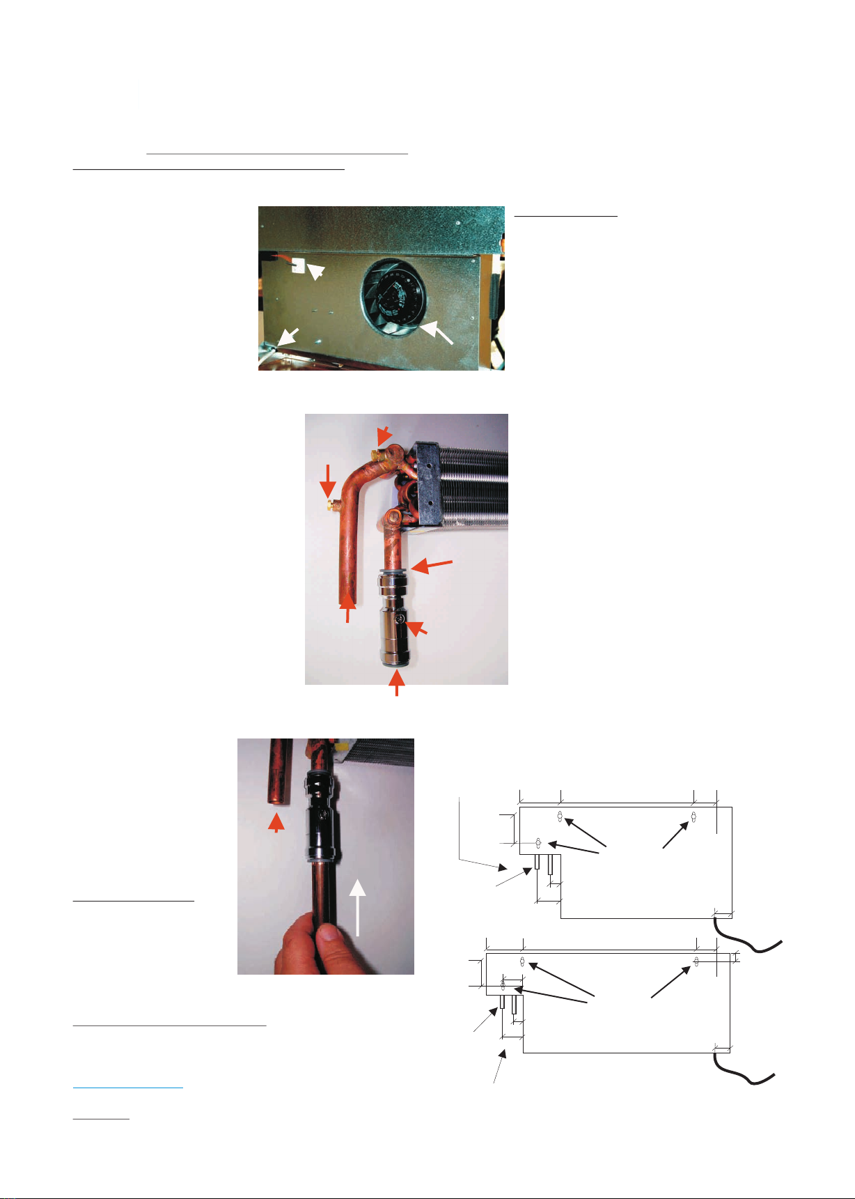
Note flow and return (opposite end to hand valve) and reduce
connections flow until Solo operates.
, and push the flow
Solo does not switch on: Check status of
pipe in as far as the end stop in the
temperature selection lights. Select the
quick connect(not supplied). Repeat for return.
highest setting, and if the light is on and not
Note that pipe should be cut with a
flashing, then some local heat source is artificially
ring cutter to avoid burrs damaging the valve seals.
heating the temperature sensor.
Open the in line valves. Connect the three core cable,
and that’s it.
To remove flow and
return pipes, turn valves
off, press downwards on
the grey plastic ring on
each quick connect(not suppied in
turn, and pull out pipes.
Once system is filled,
open highest bleed
screw until air is purged.
Piping and Pumps
Ensure that 22mm flow
and return piping is used
for all normal
installations, and each
circuit should have 6-7
Solo’s max on a 22mm
circuit.
Always use a 6m head pump.
Electrical
As Solo has an on-board 2-pole isolator, no fused spur
Cable
Fan Inlet
Air Sensor
Valve Screw
Plastic Release
Ring
Bleed Screw for wall mounted Solo
Push pipe firmly
Flow
Return
Flow
Bleed Screw for
recessed Solo
739
120.5 41.5
113
365
120.5 41.5
113
Solo 6
Solo 3
88
25
25
60
Flow
25
60
Flow
Note
Centre line of pipes
is 55mm out from rear
25
1 mm.sq twin and earth
cable entry underneath
25
Note
Centre line of pipes
is 55mm out from rear
Mounting holes
Mounting holes
Technical Manual

Water Flow Data
Water Model 6 Model 3 Capacity variation %
Flow Rate l/s Pressure Drop kPa Pressure Drop kPa Model 6 Model 3
0.12 9.9 7.5 101 101
0.10 6.9 5.4 100 100
0.08 4.5 3.6 98 99
0.06 2.7 2.1 96 97
0.05 1.8 1.5 94 96
Solo configurations
Model 06
The standard configuration features:
On board air temperature sensing
External temperature selection via keypad
PUMP
EXPANSION VESSEL
FLOW 22mm PLASTIC
RETURN 22mm PLASTIC
3-WAY VALVE
HOT WATER CYLINDER
BOILER
PUMP
EXPANSION VESSEL
FLOW 22mm PLASTIC
RETURN 22mm PLASTIC
3-WAY VALVE
HOT WATER CYLINDER
BOILER
Reverse return piping schematic
Conventional flow/return piping
The pressure characteristics of Solo were
designed to facilitate even flow sharing by
ensuring that the pressure drop at various
flow rates considerably exceeds the piping
friction loss.
Care must therefore be taken to ensure
that adequate pumping capacity exists to
guarantee adequate flow. A 6m head pump
is suggested, and approximately 6-8 Solo
units max per 22mm flow and return circuit
is recommended.It is suggested that
reverse return pipework be used where
possible.
The performance data must be derated as
outlined above if lower flow rates are opted
for.
Pipe connections to Solo are 15mm dia.
and space exists internally in the units to
allow for flow isolators if required
Solo Hydraulic Data
All data applies only to Solo Discreet Range
Technical Manual
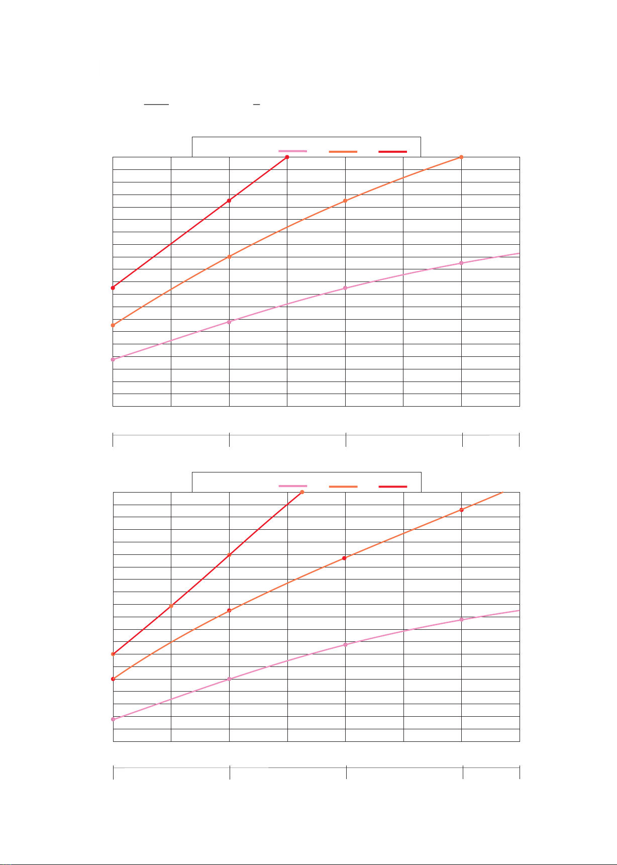
Solo Hydraulic and Airflow Data
3
Airflow m /hr
Heat Output kW
1.00
1.50
2.00
2.50
3.00
3.50
4.00
4.50
5.00
0.50
100 200 300 400
45C 65C 85C
Water Temperature Water Flow Rate 0.1 l/s
Entering Air Temp 17C
45C
65C
85C
Solo 6
3
Airflow m /hr
Heat Output kW
0.75
1.00
1.25
1.50
1.78
2.00
2.25
2.50
2.75`
0.50
0.41 0.82 1.22 1.85
45C 65C 85C
Water Temperature Water Flow Rate 0.1 l/s
Entering Air Temp 17C
45C
65C
85C
Solo 3
Air Velocity m/sec
0.45 0.91 1.36 1.82
Air Velocity m/sec
All data applies only to Solo Discreet Range
Technical Manual
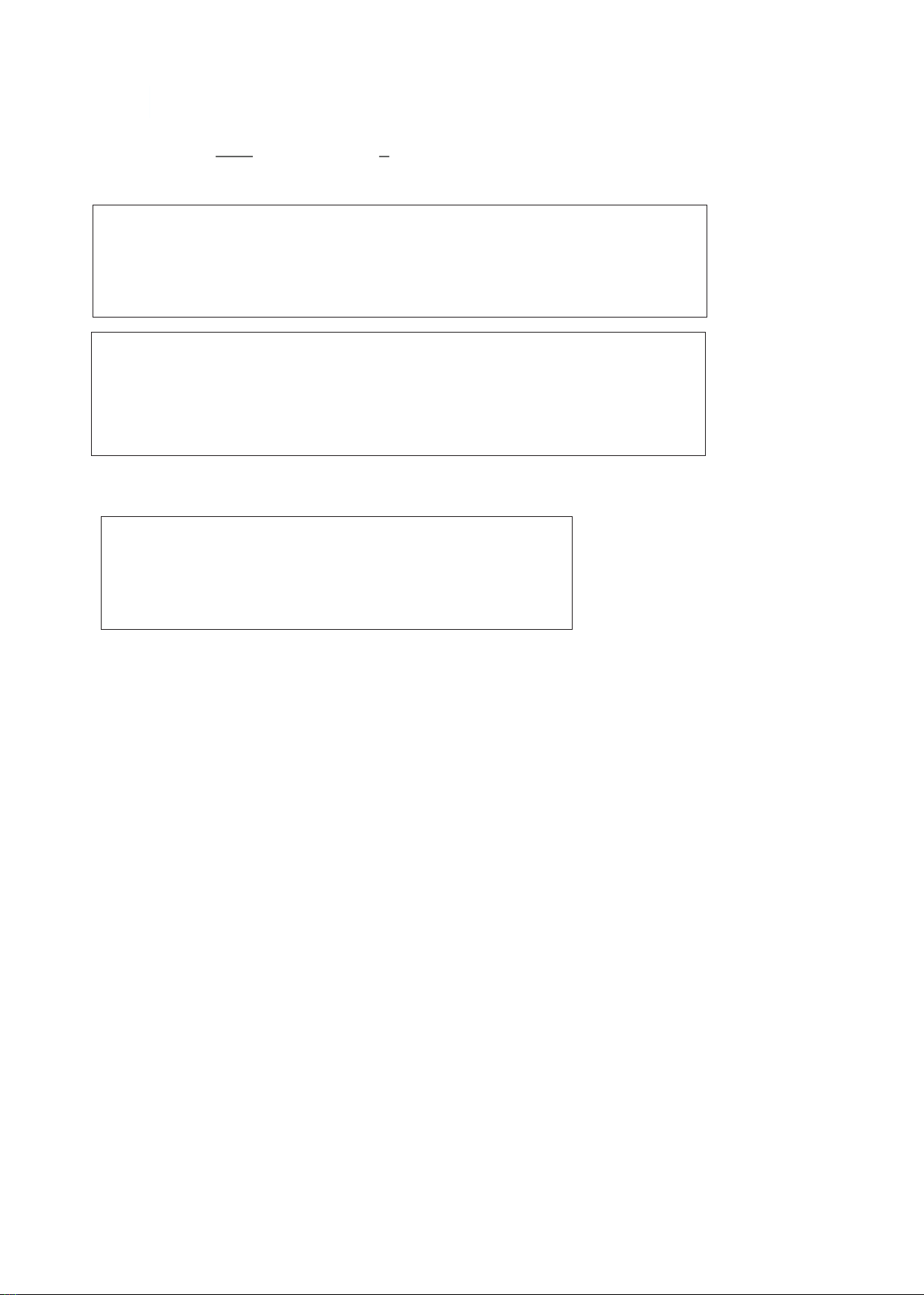
Sound Data Model 6 Model 3
Capacity Setting dBA dBA
Low 22.2 22.4
High 33.9 33.2
Boost 49.6 49.3
Note: All sound test were performed in an anechoic environment at 0.25m from the
Solo in question.
Significant improvement can be expected in a normal residential or commercial
environment with absorbent materials and surfaces
Sound and Application Data
As manufactured, Solo 6 is set such that the various capacities are as follows:
Airflow m3/hr Velocity Capacity @85C Capacity @65C Capacity@45C
Low 100 0.45m/sec 2.4kW 1.6kW 0.9kW
High 155 0.68m/sec 3.4kW 2.5kW 1.4kW
Boost 200 0.81m/sec 4.2kW 3.0kW 1.7kW
Based on entering air temperature 17C
As manufactured, Solo 3 is set such that the various capacities are as follows:
Airflow m3/hr Velocity Capacity @85C Capacity @65C Capacity@45C
Low 50 0.40m/sec 1.13kW 0.87kW 0.40kW
High 62 0.53m/sec 1.35kW 1.10kW 0.60kW
Boost 82 0.70m/sec 1.90kW 1.36kW 0.77kW
Based on entering air temperature 17C
All data applies only to Solo Discreet Range
Technical Manual

Solo installation details
739
120.5 41.5
113
365
120.5
113
Solo 6
Solo 3
88
25
25
25
60
25
60
2 x 15mm
dia. pipes
2 x 15mm
dia. pipes
Flow
Flow
1mm.sq three core
Cable entry underneath
25
1mm.sq three core
Cable entry underneath
Pipe connections are as shown, and are either 15mm dia. Plastic or copper.
Please note flow connection on LHS.
Electrical connection is via 3-core 1mm.sq or 1.5mm.sq
Trailing cable supplied with the Solo.
This is connected to a junction box or similar, and Solo is
equipped with a double pole isolator located underneath lower edge on RHS.
Centre Line of pipe conections
is 55mm out from rear of Solo
25
Technical Manual
All data applies only to Solo Discreet Range
This manual suits for next models
1
Popular Heater manuals by other brands

oventrop
oventrop Regucor Series quick start guide

Blaze King
Blaze King CLARITY CL2118.IPI.1 Operation & installation manual

ELMEKO
ELMEKO ML 150 Installation and operating manual

BN Thermic
BN Thermic 830T instructions

KING
KING K Series Installation, operation & maintenance instructions

Empire Comfort Systems
Empire Comfort Systems RH-50-5 Installation instructions and owner's manual

Well Straler
Well Straler RC-16B user guide

EUROM
EUROM 333299 instruction manual

Heylo
Heylo K 170 operating instructions

Eterna
Eterna TR70W installation instructions

Clarke
Clarke GRH15 Operation & maintenance instructions

Empire Heating Systems
Empire Heating Systems WCC65 Installation and owner's instructions


