SPX MARLEY NX User manual

NX cooling tower
INSTALLATION - OPERATION - MAINTENANCE
sea_Z1049225_C ISSUED 8/2018 READ AND UNDERSTAND THIS MANUAL PRIOR TO OPERATING OR SERVICING THIS PRODUCT.
user manual

2
contents
This manual contains vital information for the proper installation and
operation of your cooling tower. Carefully read the manual before
installation or operation of the tower and follow all instructions.
Save this manual for future reference.
Overview ........................................................................................................... 3
Safety................................................................................................................. 3
Tower Shipment............................................................................................... 4
Receiving Tower.............................................................................................. 4
Tower Location ................................................................................................ 4
Tower Installation............................................................................................. 5
Motor Wiring .................................................................................................... 6
Mechanical Equipment .................................................................................. 6
Tower Startup .................................................................................................. 7
Tower Operation.............................................................................................. 9
Water Quality and Blowdown...................................................................... 12
Tower Maintenance......................................................................................... 13
Schedule of Tower Maintenance................................................................. 18
Seasonal Shutdown Instructions ................................................................ 19
Prolonged Shutdown ..................................................................................... 20
Additional Services......................................................................................... 20
Troubleshooting............................................................................................... 22
The following defined terms are used throughout this manual to bring attention
to the presence of hazards of various risk levels, or to important information
concerning the life of the product.
Note
Indicates presence of a hazard which can cause severe personal
injury, death or substantial property damage if ignored.
Indicates presence of a hazard which will or can cause personal
injury or property damage if ignored.
Indicates special instructions on installation, operation or maintenance
which are important but not related to personal injury hazards.
Warning
Caution
Note

3
overview - safety
This User Manual as well as those offered separately on motors, fans,
Geareducer, couplings, drive shafts, float valves, pumps, etc., are intended to
assure that this cooling tower serves you properly for the maximum possible
time. Since product warrantability may well depend upon your actions, please
read this User Manual thoroughly prior to operation.
This User Manual provides information regarding general cooling tower instal-
lation and operation. Any deviation from, change or modification to, the User
Manual, the original design conditions or the original intended use of the
equipment may result in improper installation and/or operation of the tower.
Any such deviation, change or modification shall be the responsibility of
the party or parties making such deviation, change or modification. SPX
Cooling Technologies, Inc. expressly disclaims all liability for any such deviation,
change or modification. The equipment shall be warranted in accordance with
the applicable SPX Cooling Technologies Certification of Limited Warranty.
If you have questions about the operation and/or maintenance of this cool-
ing tower, and you don’t find the answers in this manual, please contact your
Marley sales representative. When writing for information, or when ordering
parts, please include the serial number shown on the cooling tower nameplate.
The following safety issues should be considered by those respon-
sible for designing the tower installation.
• Access to and from the fan deck
• Access to and from maintenance access doors
• The possible need for ladders (either portable or permanent) to
gain access to the fan deck or maintenance access doors
• The possible need for handrails around the fan deck
• The possible need for external access platforms
• Access issues due to obstructions surrounding the tower
• Lockout of mechanical equipment
• The possible need for safety cages around ladders
• The need to avoid exposing maintenance personnel to the poten-
tially unsafe environment inside the tower.
Those are only some of the safety issues that may arise in the design
process. SPX strongly recommends that you consult a safety engi-
neer to be sure that all safety considerations have been addressed.
Several options are available that may assist you in addressing some of these
personnel safety concerns, including:
— a handrail system around the perimeter of the fan deck with either one
or two ladders for access to the deck
Warning
➠
4
installation
— ladder extensions (used where the base of the tower is elevated)
— safety cages for fan deck ladders
— fan cylinder extensions
Tower Shipment
Unless otherwise specified, NX towers ship by truck (on flat bed trailers),
which lets you receive, hoist, and install the tower in one continuous opera-
tion. Single-cell towers ship on one truck. Multicell towers, depending on their
size, may require more than one truck.
Responsibility for the condition of the tower upon its arrival belongs to the
trucker—as does the coordination of multiple shipments, if required.
Receiving Tower
Prior to unloading the tower from the delivering carrier, inspect the shipment
for evidence of damage in transit. If damage is apparent, note the freight bill
accordingly. This will support your future recovery claim.
Find and remove the installation instruction drawings and bills of material
located in a plastic tote in the cold water basin. This information should be
kept for future reference and maintenance purposes.
Tower Location
Space available around the tower should be as generous as possible to pro-
mote ease of maintenance—and to permit freedom of airflow into and through
the tower. If you have questions about the adequacy of the available space
and the intended configuration of the tower, please contact your Marley sales
representative for guidance.
Prepare a stable, level support foundation for the tower, utilizing weight, wind
load, and dimensional information appearing on appropriate Marley submittal
drawings. Supports must be level to insure proper operation of the tower.
The cooling tower must be located at such distance and direction
to avoid the possibility of contaminated tower discharge air being
drawn into building fresh air intake ducts. The purchaser should ob-
tain the services of a Licensed Professional Engineer or Registered
Architect to certify that the location of the tower is in compliance
with applicable air pollution, fire, and clean air codes.
Warning
5
installation
Tower Installation
Theseinstallation instructionsare intended tohelp youprepare before
your tower arrives. If discrepancies exist between these instructions
and those shipped with the tower, the instructions shipped with the
tower will govern.
1. Prior to assembly the tower, confirm that the supporting platform is level,
and the embedded bolt, or anchor bolt holes or embedded steel plate are
correctly located in accordance with SPX drawings.
2. Make sure that the orientation agrees with your intended piping arrangement.
3. Install all the other component assemblies according to the Field Assembly
Manual.
Prior to assembly of equalizer piping or flume between towers, It is
important to confirm that the cells be firmly anchored.
Each fan blade must be located in the right hub location ensuring
the item number is the same. Ensure the fan blade pitch correct.
Fan blades and hub of one fan cannot be exchanged each other.
4. Using gaskets (by others), connect piping to the tower sump (NX1010-
NX1015 - 6"; NX1020-NX1025 -8") in compliance withdrawing instructions.
5. Using rubber grommet (NX1010-NX1015 - 5"; NX1020-NX1025 - 6"), Insert
inlet piping to the tower inlet cover in compliance with drawing instructions.
Except for horizontal components of top-mounted piping and as
prescribed on Marley drawings, do not support your pipe from the
tower or outlet connection—support it externally.
For maintenance/safety purposes, SPX recommends a lockout
type disconnect switch for all mechanical equipment. In addition
to a disconnect switch, the motor should be wired to main power
supply through short circuit protection, and a magnetic starter with
overload protection.
The insulation resistance of the motor to ground is less than 0.5MΩ.
Motors exceeding 11kw must require low voltage start-up.
Note
Note
Caution
Warning
6
Motor Wiring
Wire motor leads as shown on the motor nameplate matching the supply
voltage. Do not deviate from the motor nameplate wiring.
Internal space heaters may be present, depending upon the motor manufac-
turer. For space heater operation and wiring refer to the Marley “Fan Motor”
User Manual Z0239042.
Either of following symbols may be shown on the motor nameplate –
Δ, Δ Δ, Y, or YY. These symbols represent how the motor is constructed on
the inside and in no way have anything to do with a Delta or Wye electrical
distribution system serving the motor.
Set motor overload protection to 110% of motor nameplate amps. This setting
allows the fan motor to operate during cooler weather. During cooler weather
it is common for the motor to draw 6 to 10% higher than nameplate amps.
High amps are common during tower commissioning when the tower is dry
and the ambient air temperature is cool.
Do not start the motor more than six times per hour. Short cycling
the tower will cause fuses, breakers or O.L.s to operate and will
decrease motor life.
Changing the operational fan speed from the factory settings could
cause the fan to operate in an unstable region which may result in
damage to the equipment and possible injury.
Mechanical Equipment
Always shut off electrical power to the tower fan motor prior to
performing any maintenance on the tower. Any electrical switches
should be locked out and tagged out to prevent others from turning
the power back on.
Improper installation of the fan cylinder and fan guard will destroy
the structural integrity of the fan guard. Failure of the fan guard could
allow personnel to fall into the rotating fan.
1. Spin the fan manually to assure proper fan tip clearance (8 ±3mm). Observe
the action of the sheaves and belts to be sure that the motor is properly
parallel with the belt reducer. See Belt Tensioning and Shave Alignment.
It is essential that the fan cylinder and fan guard be installed in ac-
cordance with the Field Assembly Manual shipped with the tower.
Do not force the fan cylinder out of round.
2. Momentarily energize (“bump”) the motor and observe rotation of the fan.
The fan should rotate in a clockwise direction when viewed from above. If
Note
Warning
Warning
Warning
Caution
installation
7
rotation is backwards, shut off the fan and reverse two of the three primary
leads supplying power to the motor.
If the fan is intended to be reversed for deicing purposes, make
sure that the starter is equipped with a 2 minute time delay between
changes of direction. These delays will prevent abnormal stress
from being applied to the mechanical equipment and the electrical
circuit components.
3. Run the motor and observe the operation of the mechanical equipment. Operation
should be stable.
4. Check the torque on the fan and motor sheave and belt reducer after 10
to 60 hours of operation. See Fastener Torque Values on page 16
If the water supply system is not being operated—or if there is no
heat load on the system—motor amps read at this time may indicate
an apparent overload of as much as 10–20%. This is because of the
increased density of unheated air flowing through the fan. Deter-
mination of an accurate motor load should await the application
of the design heat load. Starting the pump before the fan motor is
normal operation.
Tower Startup
Microorganisms including Legionella bacteria can exist in premise
plumbing including cooling towers. The development of an effective
water management plan (WMP) and implementation of maintenance
procedures are essential to prevent the presence, dissemination and
amplification of Legionella bacteria and other waterborne contami-
nants throughout premise plumbing. Before operating the cooling
tower, the water management plan and maintenance procedures
must be in place and regularly practiced.
Water System:
1. Consult a knowledgeable water treatment professional to clean and treat
your new cooling tower prior to startup. Cooling towers must be cleaned
and disinfected regularly in accordance with ASHRAE Standard 188 and
Guideline 12.
2. Do NOT attempt any service unless the fan motor is locked out.
3. Remove any and all accumulated debris from tower. Pay particular attention
to inside areas of cold water basin, entire hot water basin, and hot water inlet.
Make sure that cold water suction screens are clear and properly installed.
4. For NX1010 fill the water system to an approximate depth of 50mm in the
cold water basin. For NX1015 and NX1020 80mm and for NX1025 90mm.
Note
Caution
Warning
installation
➠

8
installation
This is the recommended operating water level. Adjust the float valve so
that it is essentially closed at that level. Continue filling the system until
the water reaches a level approximately 4mm below the lip of the overflow.
5. If the tower equipped with flow-control valves (by others) completely open
flow-control and makeup valves. Start your pump(s) and observe system
operation. Since the water system external to the tower will have been
filled only to the level achieved in the cold water basin, a certain amount of
“pump-down” of the basin water level will occur before water completes
the circuit and begins to fall from the fill. The amount of initial pump-down
may be insufficient to cause the makeup valve to open. However, you can
check its operation and make sure reaching operating level. Then shut off
the makeup valves.
6. Some trial and error adjustment of the makeup float valve may be required
to balance the makeup water with tower operation. Ideally, the makeup float
valve setting will be where no water is wasted through the cold water basin
at pump shutdown. Overflow through the overflow is acceptable however
the water level after pump start-up must be deep enough to assure positive
pump suction.
7. If the tower is equipped with flow-control valves (by others) adjust to equalize
hot water depth in the distribution basins after reaching design water flow
rate. Each basin should have 72mm to 140mm water depth with uniform
depth from basin to basin. Fix valves in this position when depth is correct.
8. Continue pump operation for about 15 minutes after which it is recommended
the water system be drained, flushed, and refilled.
9. While operating the condensing water pump(s) and prior to operating the
cooling tower fan, execute one of the two alternative biocidal treatment
programs described in the following:
• Resume treatment with the biocide which had been used prior to shutdown.
Utilize the services of the water treatment supplier. Maintain the maximum
recommended biocide residual (for the specific biocide) for a sufficient period
of time (residual and time will vary with the biocide) to bring the system under
good biological control or
• Treat the system with sodium hypochlorite to a level of 4 to 5 mg/L free chlo-
rine residual at a pH of 7.0 to 7.6. The chlorine residual must be held at 4 to
5 mg/L for six hours, measurable with standard commercial water test kits.
If the cooling tower has been in operation and then shut down for a duration
of time and not drained, perform one of the two previous biocidal treatment
programs directly to the cooling water storage vessel (cooling tower sump,
drain down tank, etc.) without circulating stagnant water over the cooling tower
fill or operating the cooling tower fan.
After biocidal pretreatment has been successfully completed, cooling water
may be circulated over the tower fill with the fan off.
When biocidal treatment has been maintained at a satisfactory level for at
least six hours, the fan may be turned on and the system returned to service.
Resume the standard water treatment program, including biocidal treatment.
9
operation
Tower Operation
General:
The cold water temperature obtained from an operating cooling tower will
vary with the following influences:
1. Heat Load: With the fan in full operation, if the heat load increases, the
cold water temperature will rise. If the heat load reduces, the cold water
temperature will reduce
2. Air Wet-Bulb Temperature: Cold water temperature will also vary with the
wet-bulb temperature of the air entering the louvered faces of the tower.
Reduced wet-bulb temperatures will result in colder water temperatures.
However, the cold water temperature will not vary to the same extent as
the wet-bulb. For example, an 11°C reduction in wet-bulb may result in only
an 8°C reduction in cold water temperature.
3. Water Flow Rate: Increasing the water flow rate (m3/hr) will cause a slight
elevation in cold water temperature, while reducing the water flow rate will
cause the cold water temperature to lower slightly. However, at a given heat
load (see formula above), m3/hr reductions also cause an increase in the
incoming hot water temperature. Use care to prevent the hot water from
exceeding 44°C, in order to prevent damage to the tower components.
4. Airflow Rate: Reducing airflow through the tower causes the cold water
temperature to rise. This is the approved method by which to control leaving
water temperature. The motor may be shut off when the water temperature
becomes too cold. This will cause the water temperature to rise. When the
water temperature then becomes too warm for your process, the motor
can be restarted.
When operating in this mode care must be taken not to exceed a
total acceleration time of 30 seconds per hour.
Fan Cycling Limits:
From a dead stop, determine the number of seconds it takes the fan to arrive
at full speed. Divide this number into 30 to determine the allowable number
of starts per hour. Considering the normal fan and motor sizes used for NX
Class towers, anticipate that approximately 4 to 5 starts per hour are allow-
able. If your tower consists of two or more cells, make sure each tower cell
starts or shuts down at the same time.
Caution
Range – °F =
Heat Load (Btu/hr)
GPM x 500
or — in SI units
Range – °C =Heat Load (kW)
Water Flow (m3/hr) x 1.162
10
Freezing Weather Operation
The fill used in NX cooling towers has air entrance louvers that are molded
as an integral part of the fill. This feature makes these towers very forgiving
of cold weather operation, even at the low temperature and reduced load
conditions encountered in free cooling and other low temperature applica-
tions. Nevertheless, during operation in subfreezing weather the opportunity
exists for ice to form in the colder regions of the tower.
Slushy, transitory ice forms routinely in the colder regions of the fill
of low temperature towers, and is visible through the tower louvers.
Such ice normally has no adverse effect on tower operation, but
its appearance should be a signal to the operator to undertake ice
control procedures.
It is the operator's responsibility to prevent the formation of destruc-
tive (hard) ice on the cooling tower fill. Certain guidelines should
be followed:
1. Do not allow the tower’s leaving water temperature to drop be-
low a minimum allowable level (2° to 5°C) established as follows:
During the coldest days of the first season of operation, observe whether
any ice is forming on the louver face, particularly near the bottom of the
louver face. If hard ice is present on the louvers, an appropriate elevation
in the allowable cold water temperature is mandatory. If the coldest pos-
sible water is beneficial to your process, ice of a mushy consistency can
be tolerated—but routine periodic observation is advisable.
If the minimum allowable cold water temperature is established
at or near maximum heat load, it should be safe for all operating
conditions. However, if established at reduced load, increased heat
loads may reintroduce the potential for icing.
Having established the minimum allowable cold water temperature, maintain-
ing that temperature can be accomplished by fan manipulation. However, in
tower installations of more than one cell, where all fans are being manipulated
at the same time, Freezing weather operation of multicell towers at low cold
water temperature levels requires that the operator be especially watchful.
2. As cold air enters the louvers, it causes the water flowing over the fill to be
drawn inward toward the center of the tower. Thus, under fan operation, the
louvers and lower periphery of the tower structure remain partly dry, see-
ing only random splashing from within the tower—plus normal atmospheric
moisture from the entering air. Such lightly wetted areas are most subject
Note
Caution
operation

11
operation
to freezing. Therefore, if excessive ice forms on the louvers, stop the fan for
a few minutes. With the fan off, the water flow will increase in the vicinity
of the louvers and reduce the ice buildup.
3. Under extended extreme cold conditions, it may be necessary to operate
the fan in reverse. This forces warm air out through the louvers, melting
any accumulated ice—adequate heat load must be available. Reversal may
be at either full or half speed; however, we recommend reversal at half
speed. Reverse operation of the fan should be used sparingly and should
only be used to control ice, not to prevent it. Reverse fan operation should
not need to exceed 1 or 2 minutes. Monitoring is required to determine the
time required to melt accumulated ice.
Reverse operation of fans for prolonged periods during subfreezing
weather can cause severe damage to fans and fan cylinders. Ice can
accumulate inside fan cylinders at fan blade plane of rotation and
fan blade tips will eventually strike this ring of ice, damaging the
fan blades or cylinder. Ice can also accumulate on fan blades and
be thrown off, damaging fan cylinder or blades. Allow a minimum
of 10 minute delay between reverse operation and forward opera-
tion during subfreezing weather to permit ice to dissipate from fan
blades and fan cylinders.
4. With no heat load on the circulating water, icing cannot be controlled ef-
fectively by air control during freezing weather. Towers must not be oper-
ated with reduced water rate and/or no heat load during freezing weather.
If the circulating water system cannot be shut down, water returning from
the process should be made to bypass the tower. If a bypass is used, all
water must be bypassed without modulation. If the water bypass is directly
into the tower’s cold water basin, its design must be approved by SPX
Cooling Technologies.
Intermittent Freezing Weather Operation:
If periods of shutdown (nights, weekends, etc.) occur during freezing weather,
measures must be taken to prevent the water in the cold water basin—and all
exposed pipework—from freezing. Several methods are used to combat this.
Consult your Marley sales representative for more information.
Unless some means of freeze prevention is incorporated into your
system, the tower basin and exposed pipework should be drained
at the beginning of each wintertime shutdown period.
Warning
Caution
12
Water Quality and Blowdown
Maintaining Water Quality:
The materials used in an NX tower are selected to offer long, corrosion-free
service in a “normal” cooling tower environment, defined as follows:
• Circulating water with a pH between 6.5 and 8; a chloride content
(as NaCl) below 500 mg/L; a sulfate content (SO4) below 250 mg/L;
total alkalinity below 500 mg/L; calcium hardness (as CaCO3) above
50 mg/L.
• Startup Conditions: The water conditions during the initial tower opera-
tion are crucial in preventing premature corrosion of galvanized steel
(white rust). For at least the first eight weeks of operation, pH should
be controlled between 6.5 and 8.0 with hardness and alkalinity levels
between 100 and 300 mg/L (expressed as CaCO3).
• Chlorine (if used) shall be added intermittently, with a free residual not
to exceed 1 mg/L – maintained for short periods. Excessive chlorine
levels may deteriorate sealants and other materials of construction.
• An atmosphere surrounding the tower no worse than “moderate
industrial,” where rainfall and fog are no more than slightly acid, and
they do not contain significant chlorides or hydrogen sulfide (H2S).
• Many proprietary chemicals exist for control of scale, corrosion, and
biological growth and should be used prudently. Also, combinations
of chemicals may cause reactions which reduce treatment effective-
ness, and certain chemicals such as surfactants, biodispersants and
antifoams may increase drift rate.
The NX cooling tower structure consists primarily of galvanized steel,
therefore your water treatment program must be compatible with
zinc. In working with your water treatment supplier, it is important
that you recognize the potential effects on zinc of the specific treat-
ment program you choose.
Blowdown:
A cooling tower cools water by continuously causing a portion of it to evapo-
rate. Although the water lost by evaporation is replenished by the makeup
system, it exits the tower as pure water—leaving behind its burden of dissolved
solids to concentrate in the remaining water. Given no means of control, this
increasing concentration of contaminants can reach a very high level.
In order to achieve water quality which is acceptable to the cooling tower (as
well as the remainder of your circulating water system), the selected water
treatment company must work from a relatively constant level of concentra-
Note
maintenance

13
tions. This stabilization of contaminant concentrations is usually accomplished
by blowdown, which is the constant discharge of a portion of the circulating
water to waste. As a rule, acceptable levels on which to base a treatment
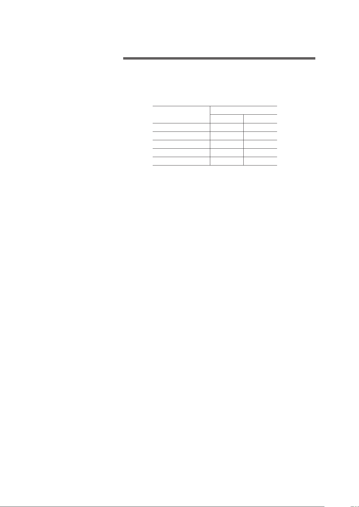
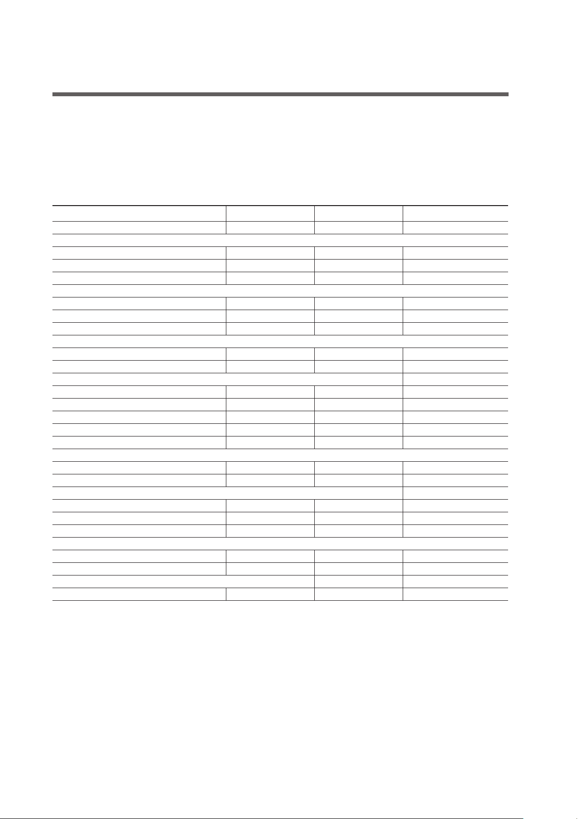
schedule will be in the range of 2-4 concentrations. The following table gives
approximate rates of blowdown (percent of total water flow rate constantly
wasted) to achieve those concentrations at various cooling ranges.*
* Range = Difference between hot water temperature coming to tower and cold water
temperature leaving tower.
EXAMPLE: 159.1 m3/hr circulating rate, 10°C cooling range. To main-
tain 4 concentrations, the required blowdown is 0.458% or .00458 times
159.1 m3/hr, which is 0.7 m3/hr.
If tower is operated at 4 concentrations, circulating water will contain four
times as much dissolved solid as the makeup water, assuming none of the
solids form scale or are otherwise removed from the system.
When water treatment chemicals are added, they should not be in-
troduced into the circulating water system via the cold water basin
of the cooling tower. Water velocities are lowest at that point, which
results in inadequate mixing.
Cooling Tower Inspection and Maintenance
Microorganisms including Legionella bacteria can exist in premise
plumbing including cooling towers. The development of an effective
water management plan (WMP) and implementation of maintenance
procedures are essential to prevent the presence, dissemination and
amplification of Legionella bacteria and other waterborne contami-
nants throughout premise plumbing. Before operating the cooling
tower, the water management plan and maintenance procedures
must be in place and regularly practiced.
In addition, the following steps are recommended:
Do NOT attempt any service unless the fan motor is locked out.
• Consult a knowledgeable water treatment professional to clean and
Note
Warning
maintenance
➠
egnaRgnilooCsnoitartnecnoCforebmuN
X5.1 X0.2 X5.2 X0.3 X0.4 X0.5 X0.6
3°C 7.83.52.81.11.80
.6
0.
6°C 5.187.15.83.52.81
.4
1.
8°C 3.2 81.187.85.83.82
.2
2.
11°C 1.3 85.1 50.187.15.83
.0
3.
14°C 9.3 89.1 23.189.46.84
.8
3.
.etarretawgnitalucricehtfo%20.0fotfirdnodesaberasreilpitluM

14
maintenance
treat your cooling tower. See Tower Startup section of this manual.
• Cooling towers must be cleaned and disinfected regularly in accor-
dance with ASHRAE Standard 188 and Guideline 12.
• Workers performing decontamination procedures must wear personal
protective equipment (PPE) as directed by their facility safety officer.
• Cooling towers must be visually inspected regularly to assess signs of
bacterial growth, appearance of debris and scale on drift eliminators
and general operating conditions. Refer to ASHRAE Standard 188
and Guideline 12 for specific frequency recommendations.
• Replace worn or damaged components.
To minimize the presence of waterborne microorganisms, including Legionella,
follow the water management plan for your facility, perform regularly scheduled
cooling tower inspections and maintenance, and enlist the services of water
treatment professionals.
For additional technical support, contact your Marley sales represen-
tative. For help identifying the sales representative in your area, visit
spxcooling.com/replocator.
References:
ashrae.org. Search “ASHRAE Standard 188” and “ASHRAE Guideline 12.”
cdc.gov. Search “Water Management Program.”
Maintenance:
Some maintenance procedures may require maintenance personnel to enter
the tower. Each cased face of the tower has a door for access to the interior
of the tower.
The fan deck ladder is designed and intended solely for personnel to gain ac-
cess to the fan deck. The little access ladder is designed and intended solely
for personnel to enter or exit the access door. The standard fan deck ladder is
an easy configuration without cage and fan deck guardrail. The optional little
access ladder is available. Another optional fan deck guardrail and double
cage ladder is also available.
The purchaser or owner is responsible for providing a safe method
for entering or exiting the access door.
Included with this instruction packet are separate User Manuals on each
major operating component of the tower, and it is recommended that you
read them thoroughly. Any discrepancies exist, the separate User Manuals
will take precedence.
Warning

15
FAN
BELT
REDUCER
SHEAVE
SHEAVE
STRAIGHT
EDGE
BELT
MOTOR
maintenance
The following is recommended as a minimum routine of scheduled maintenance.
Always shut off electrical power to the tower fan motor prior to
performing any inspections that may involve physical contact with
the mechanical or electrical equipment in or on the tower. Lock out
and tag out any electrical switches to prevent others from turning
the power back on. Service personnel must wear proper personal
protective clothing and equipment.
Belt Tensioning:
The belts are adjusted by turning the bolts on the mechanical equipment
assembly. Before tightening or loosening the belt, the eight nuts holding the
motor support in place must be loosened. After achieving proper tension,
align the mechanical equipment assembly and then retighten the eight nuts.
Ideal tension is the lowest tension at which the belt will not slip under peak
load conditions. Check tension frequently during the first 24-48 hours of run-
in operation. Over tensioning shortens belt and bearing life. Keep belts free
from foreign material which may cause slipping. Never apply belt dressing
as this will damage the belt and cause early failure. A Dodge®V-Belt Tension
Tester is an alternate method for tensioning V-belts. Check with your local
belt supplier.
Sheave Alignment:
• The motor sheave is to be positioned as close as possible to the motor
in order to minimize torque on the motor bushings.
• The bottom surface of the motor and fan sheaves must be aligned within
3mm of each other and level within 3mm in 300mm (1⁄2°) in order to not
adversely affect belt and sheave life.
• Alignment can be achieved by placing a straight edge across the top
of the sheaves making sure that it is level and measuring down to the
bottom surface of both sheaves at four points shown below.
Warning
16
maintenance
Motor/Belt Reducer Fastener Torque Values:
Weekly Visually inspect the cooling tower to assess general operating
conditions and for signs of microbial growth and appearance of debris,
scale and corrosion. Refer to ASHRAE Standard 188 and Guideline 12
for specific frequency recommendations. Consult a knowledgeable water
treatment professional to maintain cooling tower hygiene.
Observe, touch, and listen to the tower. Become accustomed to its normal
appearance, sound, and level of vibration. Abnormal aspects relating to the
rotating equipment should be considered reason to shut down the tower
until the problem can be located and corrected. Observe operation of the
motor, fan shaft bearing and fan. Become familiar with the normal operating
temperature of the motor, as well as the sight and sound of all components
as a whole.
Monthly (Weekly at startup) Inspect louvers, drift eliminators and basin
trash screens and remove any debris or scale which may have accumulated.
Replace any damaged or worn out components. Use of high-pressure water
may damage the eliminator and louver material.
Observe operation of the makeup float valve. Depress the operating lever to
make sure that the valve is operating freely.
Check for any buildup of silt on the floor of the cold water basin. Mentally
note the amount, if any, so future inspections will enable you to determine
the rate at which it is forming.
Galvanized Fastener Size
mm
Torque
ft·lb N·m
10 24-33 33-45
12 43-58 58-78
14 69-92 93-124
16 107-143 145-193
18 147-195 199-264

17
Every 3 months Lubricate belt reducer. While rotating equipment by hand,
grease the bearings with lithium based grease until a bead forms around the
seals. Mobil SHC 460 grease is recommended.
Semi-Annually Lubricate motor according to the manufacturer’s instructions.
Check to see that all bolts are tight in the fan and mechanical equipment region,
including the fan cylinder and fan guard. Refer to torque values prescribed in
the Assembly Manual. Check the belt tension and condition.
Annually Lubricate motor according to the manufacturer’s instructions. Fan
motors with sealed bearings do not require lubrication maintenance.
Check to see that all bolts are tight in the fan and mechanical equipment
region, including the fan cylinder and fan guard. Refer to torque values pre-
scribed in the User Manual
Inspect the tower thoroughly, making maximum use of instructions given in
the separate user manuals. Check structural bolted connections and tighten
as required. Make preventive maintenance repairs as necessary.
maintenance
➠
18
maintenance schedule
Maintenance Service Monthly Semi-annually Seasonal Startup or Annually
Inspect General Condition and Operation x x
Observe Operation of:
Mechanical–motor, fan and drive mechanism x x
Makeup valve (float valve and quick makeup) x x
Inspect for unusual noise or vibration x x
Inspect and Clean:
Air inlet x x
Distribution basin, nozzles and collection basin x x
Fan motor exterior x x
Check:
Collection water basin level x x
Blowdown–adjust as required x x
Belt Drive System:
Fan shaft bearing lubrication (every 3 months) every 3 months every 3 months
Check and tighten support fasteners x
Check shaft, sheave and belt alignment x
Check belt tension and condition x x
Check sheave bushing fastener torque x
Fan:
Check and tighten blade and hub fasteners x
Check fan blade pitch and tip clearance x
Motor:
Lubricate (as required) R
Check mounting bolts for tightness x
Operate at least 3 hours a month 3 hours a month 3 hours a month
Structure:
Inspect/tighten all fasteners x x
Inspect and touch up all metal surfaces x
Inspect and Paint:
Fan, motor, belt reducer and sheaves x x x
R— Refer to Component User Manual
Note: It is recommended at least weekly, that the general operation and condition be observed. Pay attention to
any changes in sound or vibration that may signify a need for closer inspection.

19
maintenance
Seasonal Shutdown Instructions
When the system is to be shut down for an extended period of time, it is
recommended that the entire system (cooling tower, system piping, heat
exchangers, etc.) be drained. Leave the basin drain open.
During shutdown, follow recommendations in the Cooling Tower Inspection
and Maintenance section of this manual before attempting repairs. During
shutdown, clean the tower and make any necessary repairs. Pay particular
attention to mechanical equipment supports and components.
Followingeach year’sshutdown and cleaning, inspectthe tower’s metal surfaces
for evidence of the need to apply a protective coating. Do not misinterpret
grime and transient rust from the piping system as a need to have the tower
painted. If relatively bright metal can be exposed by cleaning, consider that
the galvanizing has remained effective. Unless there is evidence of a general-
ized failure of the galvanizing, localized touch-up should be all that is required.
To the extent that the galvanizing (zinc coating) still exists, paint
will not adhere to it readily. Contact the manufacturer of the coating
you intend to use for instructions.
Tower Framework Check structural bolted connections and tighten as
required.
Fan Check fan assembly bolting and tighten as required.
Belt Reducer Lubricate belt reducer bearings at close of each operating
season, see page 16.
Fan Motor Clean and lubricate motor (if required) at close of each operating
season. (Refer to motor manufacturer’s recommendations). Does not apply to
motors with sealed bearings. Check motor anchor bolts and tighten as required.
Do not start motor before determining that there will be no interfer-
ence with free rotation of the fan drive.
The motor should be operated for three hours at least once a month. This
serves to dry out windings and lubricate bearing surfaces. Refer to Marley
“Fan Motor” User Manual Z0239042 for additional information.
At start of new operating season, make sure bearings are adequately lu-
bricated before returning motor to service. Does not apply to motors with
sealed bearings.
Note
Caution

20
maintenance
Prolonged Shutdown:
If shutdown period is longer than seasonal, contact your Marley sales repre-
sentative for additional information.
Additional Services
Our interest in your NX Fiberglass cooling tower does not end with the sale.
We want to make sure that you gain the maximum possible benefit from its
purchase.
Therefore, the following services are available which are intended to assure
the maximum possible service life under your operating conditions, tailor the
operating characteristics to your specific needs, and maintain consistent
optimum thermal performance capability. They are available by contacting
your Marley sales representative.
Replacement Parts:
A complete stock of parts and components is maintained at Marley plants.
In cases of emergency, they can normally be shipped within 48 hours—by air
freight if necessary. However, you would obviously benefit from anticipating
your need in advance, thus avoiding the cost of special handling.
Be sure to mention your tower model number or series number (from the
tower nameplate) when ordering parts.
Periodic Maintenance:
You may wish to contract with SPX for regularly scheduled visits —for the
purpose of inspecting and reporting your tower’s condition— to make recom-
mendations intended to prevent emergencies— and to perform maintenance
considered outside the norm.
This service is not intended to replace the important function performed by
your maintenance staff. Their attention assures the tower’s routine operating
performance, and is invaluable. However, we recognizes that the unusual
manner in which a cooling tower performs its function— as well as the unique
forces which act upon it— may be considerations which occasionally require
the services of an expert technician.
Table of contents
Other SPX Accessories manuals


