SPX Waukesha Cherry-Burrell CM User manual

Instruction Manual
Colloid Mill
Read and understand this manual prior to
operating or servicing this product.

611 Sugar Creek Road
Delavan, WI 53115
Phone: (262)728-1900 or (800)252-5200
Fax: (262)728-4904 or (800)252-5012
E-mail: [email protected]
Website: www.gowcb.com
Information contained in this manual is subject to
change without notice and does not represent a
commitment on the part of SPX Corporation. No part
of this manual may be reproduced or transmitted in
any form or by any means, electronic or mechani-
cal, including photocopying and recording, for any
purpose, without the express written permission of
SPX Corporation.
Copyright © 1997, 2010 SPX Corporation.
All Rights Reserved.
Revision Date: 08/2010
Publication: 95-03028

3
95-03028
08/2010
GENERAL INFORMATION...............................................................................................4
WAUKESHA CHERRY-BURRELL WARRANTY....................................................................................4
SHIPPING DAMAGE OR LOSS............................................................................................................4
WARRANTY CLAIM...............................................................................................................................4
SAFETY............................................................................................................................5
INTRODUCTION/SPECIFICATIONS...............................................................................6
INSTALLATION AND START-UP......................................................................................6
COLLOID MILL UNIT DIMENSIONS...............................................................................................6
1. VARIATION OF INLET PORT......................................................................................................7
2. OVERHEAD EQUIPMENT..........................................................................................................7
3. WIRING.......................................................................................................................................8
4. ROTATION...................................................................................................................................8
5. SEAL FLUSH...............................................................................................................................8
6. LUBRICATION.............................................................................................................................8
7. METHOD OF FEEDING AND CAPACITY...................................................................................8
COLLOID MILL TROUBLESHOOTING............................................................................9
MAINTENANCE .............................................................................................................10
CLEANING...........................................................................................................................................10
A. FLUSHING ...............................................................................................................................10
B. PARTIAL DISASSEMBLY:.........................................................................................................10
C. COMPLETE DISASSEMBLY: ...................................................................................................10
D. ASSEMBLY...............................................................................................................................12
ADJUSTMENTAND CALIBRATION....................................................................................................12
FLUSH WATER SEAL REPLACEMENT.......................................................................................13
GEAR CASE SERVICE.................................................................................................................14
SANITARY SEAL REPLACEMENT ....................................................................................................15
PARTS LIST...................................................................................................................15
SANITARY SEAL.................................................................................................................................15
COLLOID MILL GEAR CASE ..............................................................................................................16
COLLOID MILL FLUID HEAD..............................................................................................................18
TABLE OF CONTENTS

95-03028 08/20104
WAUKESHA CHERRY-BURRELL WARRANTY
Seller warrants its products to be free from defect in materials and workmanship for a period of one (1) year from
thedate of shipment.This warranty shall notapplytoproductswhich require repair orreplacementduetonormal
wear and tear or to products which are subjected to accident, misuse or improper maintenance. This warranty
extends only to the original Buyer. Products manufactured by others but furnished by Seller are exempted from
this warranty and are limited to the original manufacturer’s warranty.
Seller’s sole obligation under this warranty shall be to repair or replace any products that Seller determines, in
its discretion, to be defective. Seller reserves the right either to inspect the products in the eld or to request
their prepaid return to Seller. Seller shall not be responsible for any transportation charges, duty, taxes, freight,
labor or other costs. The cost of removing and/or installing products which have been repaired or replaced shall
be at Buyer’s expense.
Seller expressly disclaims all other warranties, express or implied, including without limitation any warranty of
merchantability of tness for a particular purpose. The foregoing sets forth Seller’s entire and exclusive liability,
and Buyer’s exclusive and sole remedy, for any claim of damages in connection with the sale of products. In
no event shall Seller be liable for any special consequential incidental or indirect damages (including without
limitation attorney’s fees and expenses), nor shall Seller be liable for any loss of prot or material arising out of
or relating to the sale or operation of the products based on contract, tort (including negligence), strict liability
or otherwise.
SHIPPING DAMAGE OR LOSS
If equipment is damaged or lost in transit, le a claim at once with the delivering carrier. The carrier has signed
the Bill of Lading acknowledging that the shipment has been received from SPX Flow Technology in good
condition. SPX Flow Technology is not responsible for the collection of claims or replacement of materials due
to transit shortages or damages.
WARRANTY CLAIM
Warranty claims must have a Returned Goods Authorization (RGA) from the Seller before returns will be
accepted. Claims for shortages or other errors, exclusive of transit shortages or damages, must be made in
writing to Seller within ten (10) days after delivery. Failure to give such notice shall constitute acceptance and
waiver of all such claims by Buyer.
GENERAL INFORMATION

5
95-03028
08/2010
REPLACEMENT LABEL 33-62 REPLACEMENT LABEL 33-61
Stop Machinery to Clean,
Service or Repair
WARNING
SAFETY
Read and understand this manual prior to
installing, operating or maintaining this mill.
Warnings, cautions and notes are contained in this manual. To avoid serious injury and/or possible
damage to equipment, pay attention to these messages.
WARNING Hazards or unsafe practices which COULD result
in severe personal injury or death and how to avoid it.
CAUTION Hazards or unsafe practices which COULD result
in minor personal injury or product or property damage.
NOTE Important information pertaining directly to the subject.
(Information to be aware of when completing the task.)
To avoid electrocution, ALL electrical should be
done by a registered Electrician, following
Industry Safety Standards.
All power must be OFF and LOCKED OUT
during installation.
WARNING
MILL PARTS HAVE SHARP EDGES.
TO AVOID CUTTING INJURY, WEAR GLOVES
AND HANDLE PARTS CAREFULLY.
CAUTION
TO AVOID POSSIBLE SERIOUS INJURY, SHUT
OFF AND DRAIN PRODUCT FROM MILL
PRIORTO DISCONNECTING PIPING.
WARNING
TO AVOID SERIOUS INJURY, DO NOT
INSTALL OR SERVICE MILL UNLESS
ALL POWER IS OFF AND LOCKED OUT.
WARNING

95-03028 08/20106
INTRODUCTION/SPECIFICATIONS
The Waukesha Cherry-Burrell Colloid Mill produces controlled, highly sheared, uniform dispersions and stable
emulsions made up of uniform globules of moderate neness.
A serrated conical stator and a serrated rotating cone make up the emulsifying head.
Operating clearance can be adjusted in .001-inch increments between .010 and .240 inches.
Capacities range from 6.6 to 33.3 GPM
Viscosity range is limited only by the maximum 150 psi feed pressure.
4.31 [110]
8.63 [219]
10.00 [254]
6.00 [152]
12.00 [305]
1.50 [38] TYP.
8.56 [217]
13.75 [349] MIN.
14.88 [378] MAX.
9.38 [238] MIN.
10.51 [267] MAX. 17.44 [443]
26.81 [681] AS SHOWN, WITH STATOR ALL THE WAY IN
27.94 [710] WITH STATOR ALL THE WAY OUT
3.00 [76]
Ø1.50 [38]
1.65
[42]
Ø.56 [14]
.38 KEY [10]
2"-8 IMDA INLET
2"-8 IMDA
OUTLET
1/4-18 NPT PIPE
NIPPLE SEAL
FLUSH OUTLET
1/4-18 NPT PIPE
NIPPLE SEAL
FLUSH INLET
DP100-011
SPECIFICATIONS
INSTALLATION AND START-UP
Figure 1
MODEL NOMINAL
SPEED PRESSURE
NOMINAL
CAPACITY
TO INLET
OUTLET
NOMINAL
TEMP.
RANGE
CM 3600 RPM to 150 psi
(10 bar) 6.5 to 33.3 GPM
(25 to 126 l/m) 2” San. IMDA to 200° (93° C)
COLLOID MILL UNIT DIMENSIONS
7
95-03028
08/2010
F
C B
J
X
A
G
2"-8 IMDA
Y
D
T
E
DP100-012
NOTE: The pump is shimmed to “D” height.
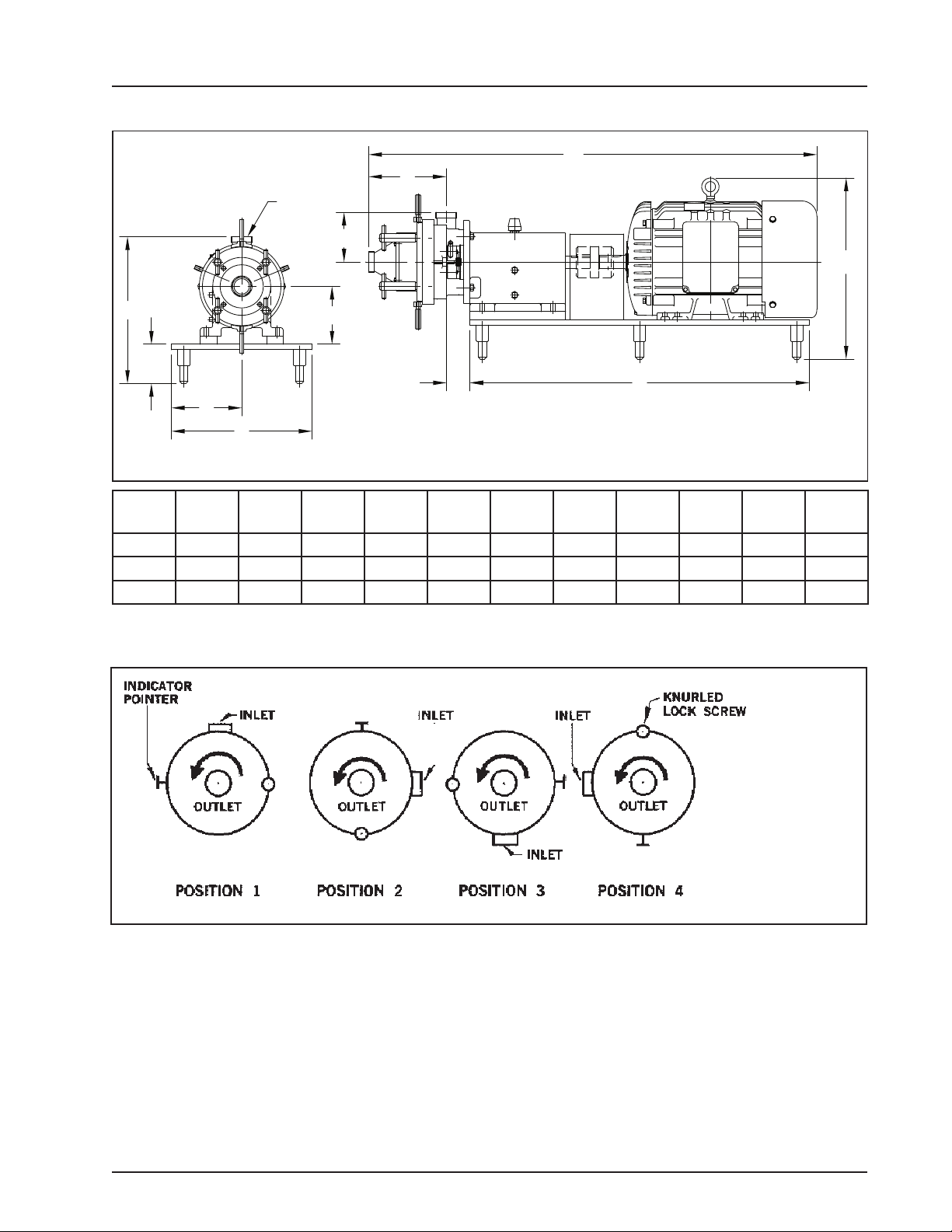
COLLOID MILL UNIT DIMENSIONS
Figure 2
UNIT
SIZE A B C D E F G J T X Y
15 HP 51.57 41.00 2.88 6.25 4.75 8.50 17.00 17.69 17.00 9.40 6.00
20 HP 53.32 41.00 2.88 6.25 4.75 8.50 17.00 17.69 17.00 9.40 6.00
25 HP 54.20 41.00 2.88 7.00 4.75 8.50 17.00 21.90 17.00 940 6.00
INSTALLATION AND START-UP
ROTATION
Counter-clockwise
when facing outlet
port.
Figure 3
1. VARIATION OF INLET PORT
The mill is shipped from the factory with the inlet port
as shown in Position 1.
Forconvenience,theinletportcanberelocatedtoanyof
theotherthreepositions(seeDisassemblyProcedure).
If Position 4 is used the calibrations at the pointer will
be upside down. We suggest the use of a mirror.
2. OVERHEAD EQUIPMENT
Follow accepted engineering practice when connect-
ing inlet and outlet with overhead equipment, piping
or tubing. Use hangers to eliminate any weight, stress
or strain on the mill. Remember, if direct connection is
made with any overhead tank, expansion joints should
be installed in the line. This will prevent mechanical
loads on the mill which would damage it, or affect its
operation.

95-03028 08/20108
GLAND
OIL LEVEL
OIL DRAIN
BREATHER CAP
7. METHOD OF FEEDING AND CAPACITY
Theinletandoutletportsare2inchsanitarymalethreads.
Theinletportislocatedin the body—itspositioncanbe
changed. (See variation of inlet port diagram; page 8).
Theoutletportislocatedinthecoverofthemill.Themill
must be fed with a pump. A Waukesha Cherry-Burrell
positivedisplacementtypepumpisrecommended.The
capacity of the mill is 400 to 2000 gallons per hour (6.6
to 33.3 gallons per minute).
INLET
OUTLET
Figure 4
Figure 5
Figure 6
INSTALLATION AND START-UP
6. LUBRICATION
Themillisshippedwithoilinthebearingcase.Thelevel
shouldbecheckedattheoillevelholeandifnecessary,
oil should be added through the oil ll hole.
Use Mobil oil DTE BB ISO Grade 220 R & O (Rust
inhibited) gear oil. (Part No. 000140001+). If DTEBB
is not available use S.A.E. 40 non-detergent mineral
oil. The mill is shipped with a solid cap screw in the oil
ll hole. This should be removed and replaced with the
breather cap which is wired to the mill.
Frequency of lubrication is dependent upon tempera-
ture and moisture conditions. If room temperature is
normal, 70° to 80° F. and water does not contact the
bearing case, change oil every 240 operating hours.
When temperature varies from hot to cold or mill is
ushed out with water, condensation will occur in the
bearing case necessitating more frequent oil changes.
Normal operating temperature of the bearing case is
170° F. to 190° F.
3. WIRING
3 Phase, 60 Cycle, 230-460 Volts. Follow wiring direc-
tions on motor. Check direction of rotation.
4. ROTATION
Counter-clockwise when facing outlet port. If run
clockwise the rotor retaining nut may back off resulting
in damage to the mill.
5. SEAL FLUSH
The mill is equipped with a face type seal which must
be water cooled. The IN and OUT ports for introducing
the water to the seal are located in the gland (1) They
are 1/4-inch pipe nipples, but the IN hole is smaller
than the OUT hole to prevent over-pressurizing.
(Figure 4)
The IN port must be used and the ow of water must
be throttled to produce a ush of 1/2 to 1 quart per
minute. Flows in this range provide safe cooling
without damage to lip seal.
It is recommended that a solenoid valve be used in
the water line to turn on the water simultaneously
with the mill. If the solenoid valve is not used the
water ush line should be turned on before starting
mill.

9
95-03028
08/2010
COLLOID MILL TROUBLESHOOTING
PROBLEM LIKELY CAUSE SOLUTION(S)
Seals leaking Exceeding 150 PSI pressure limitation of
pump Open up gap reduce pressure
Seal ush water improperly plumbed Connect ush water to IN/OUT ports
as stamped on gland
Water pressure too high Adjust to 1/2-one quart per minute
Seals misaligned on pins Re-align seals to proper t.
Noisy operation /
Excessive power draw Loose rotor nut causing rotor to stator
contact Tighten nut to 75 ft-lbs.
Check mill rotation
(counterclockwise facing outlet port)
Inconsistant milling
results Loose adjusting ring Set gap and tighten knurled screw
in hole. Tighten bolt and nut on
opposite side.
Worn rotor or stator Replace worn parts

95-03028 08/201010
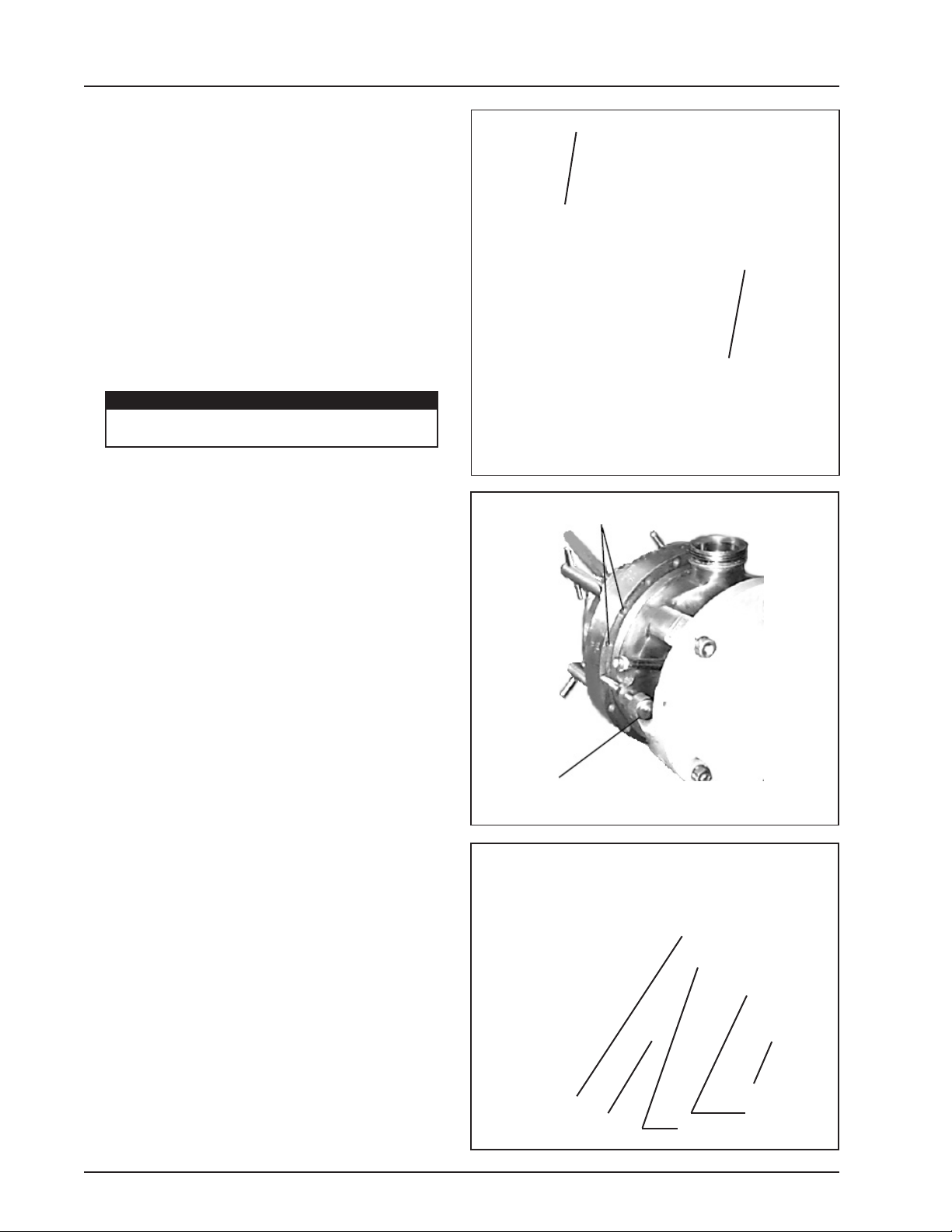
B. PARTIAL DISASSEMBLY:
Caution: Handle all parts carefully to avoid nicks and
scratches which will be detrimental to operation of the
mill.
1. Remove “T” handles.
2. Back out knurled lock screw.
3. Pull the cover/stator assembly outward. Some
resistance to stator movement will be encountered
which is due to friction from the o-ring.
As soon as the o-ring is free, the cover and stator
assembly can be easily removed. It is not necessary to
removeadjustingring. Disassemblytothispointallows
complete drainage.
NOTE: To prevent wearing of the faces between the
adjusting ring and stator, it is recommended that these
surfaces be lubricated occasionally with an approved
silicone type lubricant.
T-HANDLE
KNURLED LOCK
SCREW
Figure 7
O-RING ADJUSTING RING
Figure 8
MAINTENANCE
C. COMPLETE DISASSEMBLY:
1. Follow 3 steps outlined in B.
2. Remove cover capscrews and pull off cover, then
remove the o-ring.
3. Pull stator off studs and remove o-ring.
COVER
STATOR O-RING
O-RING
Figure 9
CLEANING
A. FLUSHING
In some instances the unit can be cleaned by merely
ushing water through it while the mill is in operation.
However, some of the water will remain in the bottom
of the cone shaped stator. If this is not permissible it
is then recommended that the unit be dismantled for
cleaning.

11
95-03028
08/2010
MAINTENANCE
4. Remove rotor retaining nut and disassemble
o-ring.
5.Sliderotoroffshaft,handlewithcaretoavoiddamage
to rotor or seal seat which is contained in rotor.
6. Gently pull seal seat from back of rotor and remove
o-ring.
7. Remove seal assembly from shaft.
8. Remove four 1/2-13 hex nuts which secure body to
bearing case and slide body off.
9. Remove four capscrews from gland on back side
of body and disassemble gland. There are six loose
springs in the gland. The gland lip seal can be pressed
out if replacement is required.
10. Remove o-ring from inside body. Use o-ring tool if
necessary.
NOTE:Cleanandinspectallpartsthoroughly.DONOT
reuse seal or seal seat if scratched, chipped or worn.
5.
9.
SPRINGS
8.
7. 8.
Figure 10
Figure 11
O-RING
4.
SEAL SEAT
O-RING
6.
10. O-RING
LIP SEAL
9.
95-03028 08/201012
D. ASSEMBLY
1. Apply a suitable lubricant to all o-rings and insert
them in their respective grooves.
NOTE:Sealseato-ringshouldbeplacedoversealseat
and then seat inserted into rotor.
2. Follow disassembly procedure in reverse order to
complete assembly. (Torque rotor nut to approximately
75 ft-lbs.)
3. Seal water to mill must be connected to gland
connection marked IN. Inlet of gland contains the
smaller hole. Outlet contains the larger hole. (See
Figure 12).
ADJUSTMENT AND CALIBRATION
The mill can be adjusted to have a clearance between
the rotor and the stator from a minimum of .010 inches
to a maximum of .240 inches in increments of .001
inches.
The body (1) and the adjusting ring (3) are calibrated
as a unit and serialized, they must not be interchanged
with other Waukesha Cherry-Burrell Colloid Mills.
The stator is held rmly against the adjusting ring by
“T” handles (Figure 14).
The clearance between rotor and stator is adjusted by
turningtheadjustingringcounterclockwise(whenfacing
theoutletport)forincreasedclearanceandclockwiseto
decreasetheclearance.Theadjustingringisengraved
withnumeralsindicatingtheclearance in incrementsof
.010inches.Theindicatorpointerindicatesthe desired
clearance. For setting in between the increments of
.010 the drill point spacing is equal to .001 clearance.
Drill point spacing coincides with locking hole spacing.
There are 18 locking holes in the ring, spaced 20°
apart. (Figure 13)
Rotationoftheringby20°(holetoholedistance)changes
the milling clearance by .001 inches.
Example:toobtain0.014radialclearance,locate0.010
punch mark under pointer. Turn ring counterclockwise
four additional drill points {or locking holes), and lock
in place with knurled lock screw. (Figure 13) Tighten
‘’T” handles to rmly hold stator against adjusting ring.
Clearance will be 0.014 inches. Adjust lock bolt and
tighten nut. (Figure 14)
LOCKING HOLES
STATOR
ADJUSTING RING
T-HANDLES
KNURLED
LOCKING
SCREW
INDICATOR
IN
OUT
SMALL HOLE (IN)
WATER FLUSH SYSTEM
LOCK BOLT
MAINTENANCE
Figure 12
Figure 13
Figure 14
LARGE HOLE
(OUT)
CAUTION
Flushing backwards can cause seal leakage
and ush media will enter product zone.

13
95-03028
08/2010
1. Disassemble as described in Maintenance, Item C,
complete sanitary disassembly.
2. Remove four nuts. (Figure 15)
REMOVE BODY NUTS (4)
REMOVE BODY
REPLACE LIP SEAL
3. Slide body (1) forward off shaft. (Figure 16)
4. Pull seal out with hook tool. Insert new water lip seal
with lip facing in. (See Item 18, Figure 22)
5. Re-assemble in reverse order.
FLUSH WATER SEAL REPLACEMENT
MAINTENANCE
Figure 15
Figure 16
Figure 17

95-03028 08/201014
Tools required for seal and/or bearing replacement:
• Assorted hand tools including soft hammer.
• Bearing puller or press.
• Hook tool for seal removal.
• Spanner wrench for bearing retainer nut removal
• Wrench GD0019000 for rotor nut..
• Anti-seize and seal lubricating grease.
• 2 quarts DTE BB Mobil oil or equivalent.
Service Preparation
1. Shut OFF and lock out all power.
2. Remove all product and ushing from mill.
3. Disconnect all piping to mill.
4. Remove pump anchor screws and slide gearcase
off motor coupling.
5. Place mill on sturdy work surface.
6. Disassemble wet end of mill completely. (See
Page 11 for Disassembly)
7. Drain oil from gear case. (Figure 18)
Front Seal Replacement (Figure 19)
1. Remove slinger. (Pull off)
2. Remove bearing retainer assembly (front seal
inside) (Held in place with four (4) capscrews).
4. Note seal lip position and knock out old seal, place
lubrication around new seal and press into bearing
retainer. Replace gasket, if necessary. Lubricate seal
lip and install bearing retainer and slinger.
Rear Seal Replacement (Figure 20)
1. Pull rear oil seal off drive shaft with hooked tool.
2. Place tape over shaft keyway and install new seal.
(Lubricate seal lip before sliding onto shaft).
Bearing Replacement
1. Remove rear seal. Remove rear bearing retaining
ring. Press drive shaft out through front of gear case
(through rear bearing). (Figure 20)
2. Remove bearing locknut from shaft (counter-
clockwise) and press front bearing off. (Fig. 19)
3. Press the rear bearing out of the front of gear
case. (Fig. 20)
4. Clean and lubricate all parts thoroughly before
reassembling. Do not unwrap new bearings until
ready to install.
5. Lubricate inner races and press new bearings onto
shaft. Tighten locknut on front bearing to 40 ft-lbs.
(Fig. 21)
6. Lubricate outer races and press shaft assembly
into case. Replace retaining ring and rear seal. (Fig.
17)
7. Replace mill assemblies. Torque rotor nut to 75 ft-
lbs. Rell crankcase with 2 quarts Mobil DTE BB oil.
Figure 18
Figure 19
Figure 20
Figure 21
BEARING RETAINER
ASSEMBLY
SLINGER
OIL LEVEL
OIL DRAIN
GASKET
FRONT BEARING
LOCKNUT
FRONT SEAL
REAR SEAL RETAINING RING
REAR BEARING
GEAR CASE SERVICE
MAINTENANCE
BREATHER CAP
To avoid cutting injury, wear gloves
and handle parts carefully.
CAUTION

15
95-03028
08/2010
NOTE: Use care at all times to avoid chipping or
scratching seal or seat .Keep seal face areas clean
and dry.
1. Install lip seal (18) into rear of gland plate (17).
2. Apply a small amount of sealant to one end of
each of the six springs (19) and place in gland spring
holes (17).
3. Apply gasket (16) to the sealing face of the gland
plate (17).
4. Attach gland plate (17) to mill body using existing
capscrews.
5. Install one o-ring (24) into groove in mill body.
6. Attach body to bearing case (4 nuts).
7. Lubricate o-ring (24) and small O.D. of seal (20)
with a compatible lubricant and install seal into mill,
aligning notches on the seal with pins in gland plate.
Avoid grease type lubricants which can harden and
bind the seal; use food grade lubricant when process-
ing food products.
8. Lubricate remaining o-ring (24) with compatible
lubricant and install on small O.D. of seat (21).
9. Install seat (21) (with pins and o-ring) into rear of
rotor, aligning pins with holes in rotor.
10. Install rotor onto shaft, being careful to avoid
damage to the seat (21) or seal (20).Tighten rotor
nut to 75 ft-lbs.
11. Complete mill assembly. (Reverse steps 2 and 3
on page 13.)
SANITARY SEAL REPLACEMENT
MAINTENANCE
Figure 22
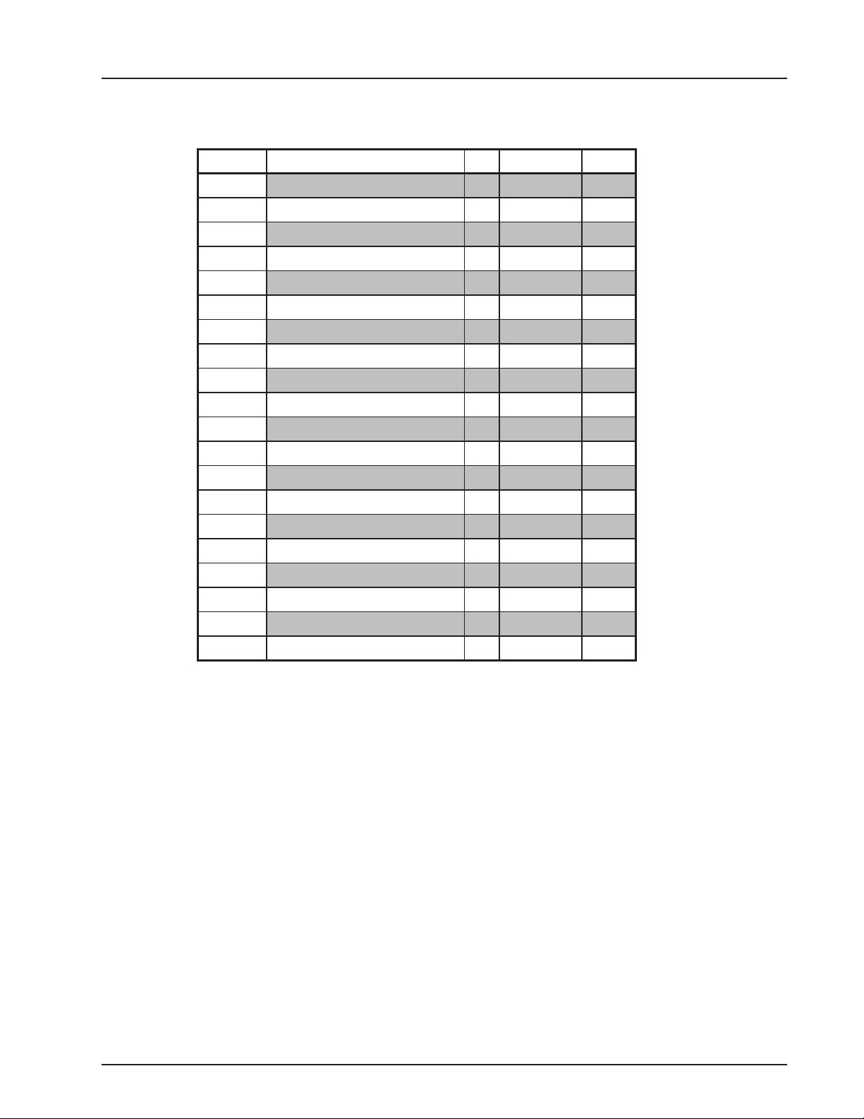
KIT # 35379+ Convert single spring seal to multiple
spring seal
SANITARY SEAL
ITEM
NO. DESCRIPTION QTY PART NO.
16 Gland Gasket 1 0MS042G00
17 Gland Plate 1 0MS058200
18 Gland Plate Seal 1 0MS030200
19 Spring 6 0MS304200
20 Stationary Seal, Carbon 1 0MS306003
Stationary Seal, Silicon Graphite 1 0MS306004
Stationary Seal, Silicon Carbide 1 0MS306009
21 Rotating Seat, Silicon Graphite 1 0MS014002
22 Capscrew 4 30-98
24 Seal Seat & Body O-ring, FKM 2V70150
Seal Seat & Body O-ring, Silicone 2S75150
PL5081-CH11
PARTS LIST
95-03028 08/201016
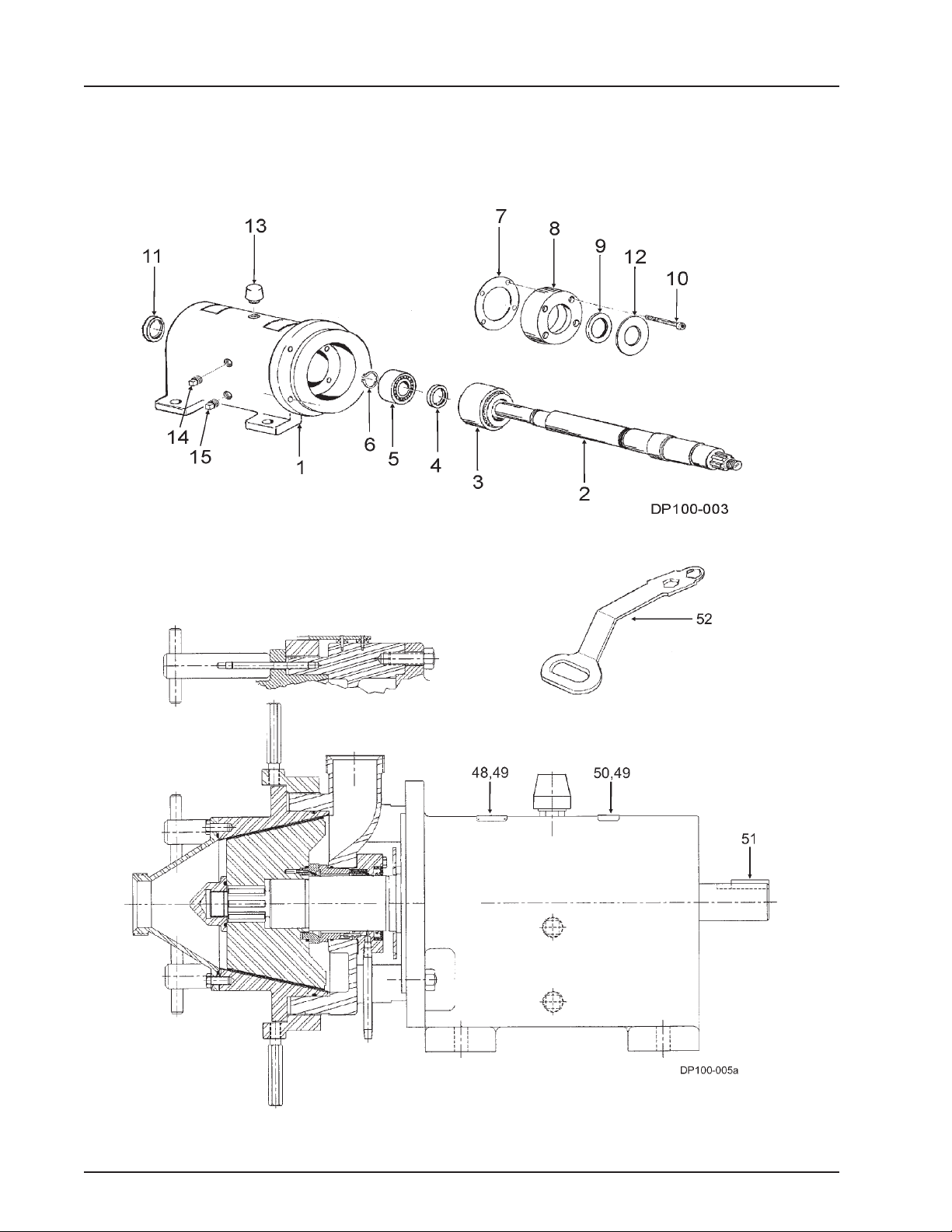
COLLOID MILL GEAR CASE
Figure 23
PARTS LIST
17
95-03028
08/2010
PARTS LIST
ITEM NO. DESCRIPTION QTY PART NO. NOTES
1Gear Case 1 0MS005000
2Drive Shaft 1 0MS008000
3Front Bearing 1 0MS036300
4Bearing Locknut 1 0MS036N00
5Rear Bearing 1 0MS036000
6Retaining Ring 1 BD0087R00
7Front Bearing Retainer Gasket 1 0MS042B00
8Front Bearing Retainer 1 0MS080000
9Pump End Shaft Seal 1 0MS030100
10 Capscrew 4 30-274
11 Drive End Shaft Seal 1 0MS030000
12 Slinger 1 0MS045000
13 Breather 1 115800
14 Level Indicator 1 115799
15 Drain Plug 1 115798
48 Nameplate, Sanitary 1 001061002
49 RHDS 6 30-355
50 Caution Label, Yellow 1 33-62
51 Key 1 000037003
52 Rotor Nut Wrench 1 109896
PL5081-CH12
COLLOID MILL GEAR CASE
95-03028 08/201018
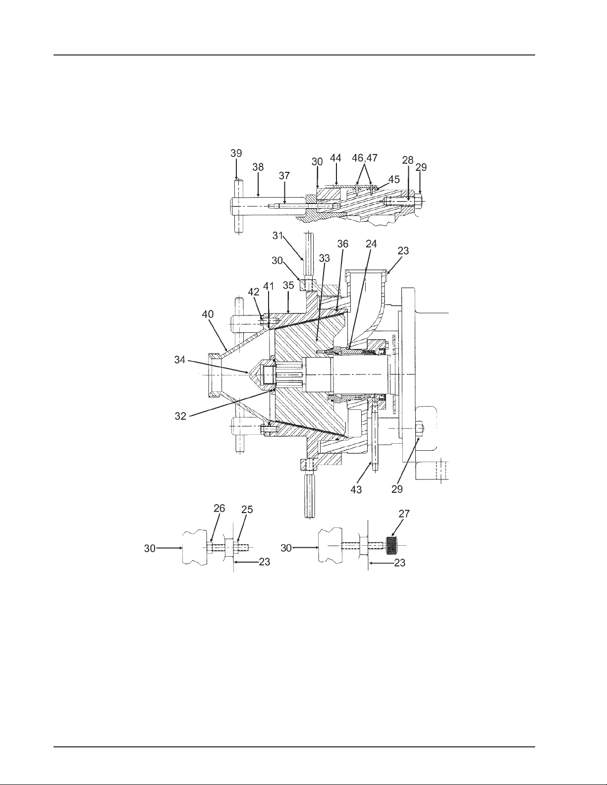
PARTS LIST
Figure 24
COLLOID MILL FLUID HEAD
NOTE:
Torque rotor nuts
to 75 ft-lbs
Used to set adjusting
ring at minimum
setting of 0.010” Used to hold
adjusting ring
setting
NOTE:
Body rotor
clearance starts
at 0.101” and
ends at 0.220”
in increments of
0.010”

19
95-03028
08/2010
PARTS LIST
ITEM NO. DESCRIPTION QTY PART NO. NOTES
23 Body, 2” Bevel Seat 1 0MS001000
Body, 2” TCF 1 35886
24 Seal Seat & Body O-ring, FKM 2 V70150
Seal Seat & Body O-ring, Silicone 2 S75150
25 Hex Nut 1 36-55
26 Capscrew 1 30-86
27 Knurled Lock Screw 1 0MS129000
28 Stud - Body 4 0MS011000
29 Hex Nut 4 36-70
30 Adjusting Ring 1 0MS003000
31 Adjusting Ring Handle 2 0MS054000
32 O-ring, Rotor Nut, FKM 1 V70222
O-ring, Rotor Nut, Silicone 1 S75222
33 Rotor 1 0MS010000
34 Rotor Retaining Nut 1 0MS052000
35 Stator 1 0MS004000
36 O-ring, Stator, FKM 1 V70263
O-ring, Stator, Silicone 1 S75263
37 Stud, Handle Shaft 4 0MS011100
38 Handle Shaft 4 0MS099000
39 Handle Pin 4 0MS100000
40 Cover, 2” Bevel Seat 1 0MS002000
Cover, 2” TCF 1 35887
41 O-ring, Cover, FKM 1 V70253
O-ring, Cover, Silicone 1 S75253
42 Capscrew 4 30-151
43 Pipe Nipple 2 0MS018000
44 Indicator 1 0MS056100
45 Spacer 2 0MS454000
46 Machine Screw 2 30-299
47 Lockwasher, #10 2 43-21
PL5081-CH13
COLLOID MILL FLUID HEAD

95-03028 08/201020
NOTES
Table of contents
Other SPX Power Tools manuals


Popular Power Tools manuals by other brands

Festool
Festool ROTEX RO 90 DX FEQ Original instructions

Hilti
Hilti BX 3-BT Original operating instructions

Berner
Berner BJS-SHO 160 Original instructions

Josef Kihlberg
Josef Kihlberg JK35-590 Repair instructions

FOREDOM
FOREDOM H Series Assembly, operation and service manual

Lister
Lister Star Instruction book and parts list


