blackburn TBM15CR-LI User manual

Operating Instructions
FOR TBM15CR-LI
HYDRAULIC COMPRESSION TOOL
TA04721 B Page 1 of 8
Page
1.0 GENERAL INFORMATION......................................................... 2
1.1 Safety Rules........................................................................... 2
1.2 Features................................................................................. 2
1.3 Specifications......................................................................... 2
2.0 Parts & Accessories .................................................................. 3
2.1 Hydraulic Compression Tool................................................... 3
2.2 Battery. .................................................................................. 3
2.3 Charger.................................................................................. 3
2.4 Battery Adapter. ..................................................................... 3
2.5 Carrying Case ........................................................................ 3
3.0 Operating Instructions .............................................................. 4
3.1 Charging the Battery. ............................................................. 4
3.2 Attaching & Detaching the Battery.......................................... 4
Page
3.3 Compression Cycles .............................................................. 4
3.4 Switch Operations.................................................................. 4
3.5 Compression Operation ......................................................... 5
3.6 Maintenance & Operation....................................................... 5
3.7 Trouble Shooting.................................................................... 5
4.0 Important Operation Precautions ............................................ 6
4.1 Precautions for the Compression Tool .................................... 6
4.2 Precautions for the Battery. .................................................... 6
4.3 Precautions for the Charger.................................................... 6
5.0 Parts Breakdown....................................................................... 7
5.1 Parts Diagram ........................................................................ 7
5.2 Parts List................................................................................ 8
Table of Contents

IMPORTANT: Read and understand all of the
instructions and safety information in this manual
before operating or servicing this tool.
1.0 GENERAL INFORMATION
SAFETY RULES
1.1
1. BE FAMILIAR WITH YOUR TOOL.
Read the instruction manual. Become aware of its proper
usage as well as the potential hazards.
2. KEEP WORK AREA CLEAN AND WELL LIGHTED.
Poor lighting and cluttered areas invite accidents.
3. USE SAFETY GLASSES.
4. MAINTAIN TOOL WITH CARE.
Keep tool in good condition at all times. Keep it clean for
best and safest performance.
5. DON'T OVER-REACH.
Keep proper footing and balance at all times.
6. NEVER ATTEMPT TO MAKE A COMPRESSION ON A
"HOT" LINE.
Never assume the power is OFF! Determine beforehand if
any electrical hazards could exist when making a
connection to a line or wire.
7. KEEP FINGERS AND OTHER BODY PARTS AWAY
FROM COMPRESSION DIES & MOVING PARTS.
WARNING
Tools are NOT insulated for use on or near
energized conductors. Use of these tools
near energized conductors may lead to
electrical shock, causing severe injury or
death. DO NOT use these tools near
energized conductors without adequately
insulating operator and surroundings.
WARNING
Pinch point hazard. Compression Dies at high
force can cause severe personal injury. Keep
all body parts away from moving parts of the
tool during operation.
FEATURES1.2
• Fully automatic, self-contained power tool.
• Removable battery cartridge - simply change the
cartridge for continuous use.
• One handed operation - control ram advancement
and retraction with one hand.
• Protective rubber boot on Head.
SPECIFICATIONS
HYDRAULIC COMPRESSION TOOL:
TBM15CR-LI
Drive Unit: 1
4.4V DC Motor
Dimensions:
21.5”L x 3.5”W x 10.5”H
Weight:
24 lbs. with battery
Capacities:
Cu #8-1500 Kcmil
AL #10-1250 Kcmil
Jaw Opening:
2.00”
Output:
15 Tons
144-BAT-LI
BATTERY:
Battery Type: Sealed Lithium Ion
Voltage:
14.4V DC
Dimensions:
4.2”L x 3.3W x 2.6H
Capacities:
3.0Ah
Weight:
1.2 lbs.
Charging time:
25 min. 80% Capacity
45 min. 100% Capacity
CHARGER:
144-CHR-LI
Input Voltage: 120 - 240 V AC Single Phase
Dimensions:
9”L x 5.7W x 3.2H
Weight:
3.5 lbs.
1.3
TA04721 B Page 2 of 8

TA04721 B Page 3 of 8
HYDRAULIC COMPRESSION TOOL
2.1
(TBM15CR-LI)
RAM
Die Release
Pins
Strap Ring
Head
Release
Pin
Strap Ring
LED Indicator
Advance Button
Release Button
Air Vent
Contact Cover
Air Vent
Release
Button
Contacts
BATTERY
(
144-BAT-LI
)
2.2
CHARGER
(
144-CHR-LI
)
2.3
LED Lamp Contacts
Air Vent
Power Cord Inlet Power Cord
BATTERY ADAPTER (144-ADP-LI)
2.4
CARRYING CASE
2.5
2.0 PARTS AND ACCESSORIES

TA04721 B Page 4 of 8
CHARGING THE BATTERY
3.1
LED Lamp
Battery
Power Cord
Charger
1. Connect the power cord to the Charger 144-CHR-LI and to an AC
outlet. The LED Lamp blinks in Red [STAND BY]
NOTE: The rated input voltage for this unit is 100V-240V. Use of
voltages over 260V will result in damage to the charger.
2. Insert the Battery rmly into the charger.
The LED Lamp lights in green [CHARGING].
NOTE: Do not short-circuit the Charger by placing foreign materials
in the contacts on Charger, as this will damage the Charger.
3. Charging takes approximately 25 minutes (80% capacity) and
45 minutes (100% capacity).
When charging is nished, the LED Lamp lights in orange
[COMPLETION].
NOTE: If the LED Lamp displays solid red [HIGH TEMPERATURE],
remove the Battery from the Charger and allow it to cool down
before trying to charge it again.
4. When the battery will no longer charge or hold a charge, the LED
Lamp blinks quickly in red [IMPOSSIBLE TO CHARGE].
5. When the charger is out of order, the LED Lamp does not light up
even if AC power is supplied.
NOTE: Do not power the Charger with a portable generator.
ATTACHING & DETACHING THE BATTERY PACK
3.2
1. To attach the Battery, slide it into the Battery Adapter at
the rear of the Tool until it stops and the Latches engage.
2. After inserting the Battery, check that it is securely in
place by pulling it gently without pressing the Latches.
3. To detach the Battery, pull out the Battery while pressing
the Latches.
Tool
Battery Adapter
Battery
Slide in
Pull Out
Latches
(both sides)
COMPRESSION CYCLES
3.3
This guide indicates the number of compression cycles that
the TBM15CR-LI can be expected to perform when the
battery is fully charged. These gures are approximate and will
vary according to the charging and other operating conditions,
such as temperature, humidity, and battery condition.
CONDUCTOR
AVERAGE COMPRESSIONS
PER CHARGE
BAT-144-LI
4/0 Cu 120
500 kcmil 100
750 kcmil 60
3.0 OPERATING INSTRUCTIONS
SWITCH OPERATIONS
3.4
1. The ram advances when the Advance Button is
depressed and stops when the Advance Button is
released.
2. To retract the ram, depress the Release Button. The ram
continues to retract while the Release Button is
depressed.
Advance Button Release Button

TA04721 B Page 5 of 8
COMPRESSION OPERATION
3.5
1. Select the appropriate size dies for the connector being used.
2. Insert the Dies into the Head side and Ram side by sliding the
dies in while pressing the Die Release Pin. If needed, the
head can be opened for easier access by pulling the Head
Release Pin. IMPORTANT: Prior to compression, make sure
the head is closed and the Head Release Pin is fully
engaged.
3. Place the connector between the dies. Press the advance
button and advance the Ram so the connector is held lightly
between the dies. Do not deform the connector.
4. Insert the conductor into the connector.
5. Press the advance button until the compression is complete.
A series of clicks will be heard followed by a release in the
pressure when compression is complete. If the LED indicator
(Step 2.1) shows RED during compression, the battery
charge level is low but enough to complete the compression.
The battery should be charged before next use.
6. Press the release button (Step 3.4) to retract the ram. The
ram continues to retract while the release button is pressed.
The ram stops when it is fully retracted.
7. Remove the compressed connector from the tool.
Dies
Die Release Pin
(Head Side)
Die Release Pin
(Ram Side)
Head Release Pin
WARNING
Pinch point hazard. Compression Dies at high
force can cause severe personal injury. Keep
all body parts away from moving parts of the
tool during operation.
MAINTENANCE & INSPECTION
3.6
1. Very little maintenance is required to ensure that the tool is kept in good working condition.
2. To ensure smooth operation and prevent rust, store the tool in a cool dry area. Ensure that moving parts are lubricated regularly.
3. When the plastic housing becomes dirty, clean it with a soft soaped cloth.
4. Dust, sand, and dirt are a danger for any hydraulic device. After each use, the tool should be wiped with a clean cloth taking care
to remove any residue, especially close to the movable parts.
5. If the tool is maintained regularly, it should provide you with trouble free service.
NOTE: Always remove the battery pack from the unit before replacing parts or maintenance.
TROUBLE SHOOTING
3.7
Problem Cause Solution
Charger LED lamp indicates stand by while battery
is inserted.
There is dust or foreign objects lodged at
the battery contacts. Remove foreign objects.
The charger LED lamp indicates high or low
temperatures. The battery is too hot or cold. Allow the cartridge to reach room temperature
before continuing.
The motor does not operate at all.
The battery is not charged or defective. Charge or replace the battery.
There is dust or foreign objects lodged at
the battery contacts. Remove foreign objects.
The switch is misaligned. Check to see if switch is aligned with advance
button, consult tool service.
The motor runs but ram will not advance, or ram
advances but will not build pressure.
Consult tool service.
Air in hydraulic system.
Insufcient hydraulic oil.
Hold the tool with head towards the oor to
allow air to rise towards top of oil bladder.
Defective hydraulic circuit. Consult tool service.
The ram will not retract
Tool did not complete a full cycle and
bypass.
Depress advance button and allow tool to
reach full pressure and bypass, then depress
release button to retract the ram.
The connector is jammed in compression
dies.
Depress and hold release button while prying
compression dies apart.
The release button is bent or misaligned. Consult tool service.

TA04721 B Page 6 of 8
4.0 IMPORTANT OPERATING PRECAUTIONS
WARRANTY: Thomas & Betts sells this product with the understanding that the user will perform all necessary tests to determine the suitability of this
product for the user's intended application. Thomas & Betts warrants that this product will be free from defects in materials and workmanship for the
period stated on the enclosed warranty card. Upon prompt notication of any warranted defect, Thomas & Betts will, at its option, repair or replace
the defective product. Misuse, misapplication or modication of Thomas & Betts products immediately voids all warranties.
Limitations and Exclusions: THE ABOVE WARRANTY IS THE SOLE WARRANTY CONCERNING THIS PRODUCT, AND IS IN LIEU OF ALL OTHER
WARRANTIES EXPRESS OR IMPLIED, INCLUDING BUT NOT LIMITED TO ANY IMPLIED WARRANTY OF MERCHANTABILITY OR FITNESS
FOR A PARTICULAR PURPOSE, WHICH ARE SPECIFICALLY DISCLAIMED. LIABILITY FOR BREACH OF THE ABOVE WARRANTY IS LIMITED
TO COST OF REPAIR OR REPLACEMENT OF THE PRODUCT, AND UNDER NO CIRCUMSTANCES WILL THOMAS & BETTS BE LIABLE FOR
ANY INDIRECT, SPECIAL, INCIDENTAL OR CONSEQUENTIAL DAMAGES.
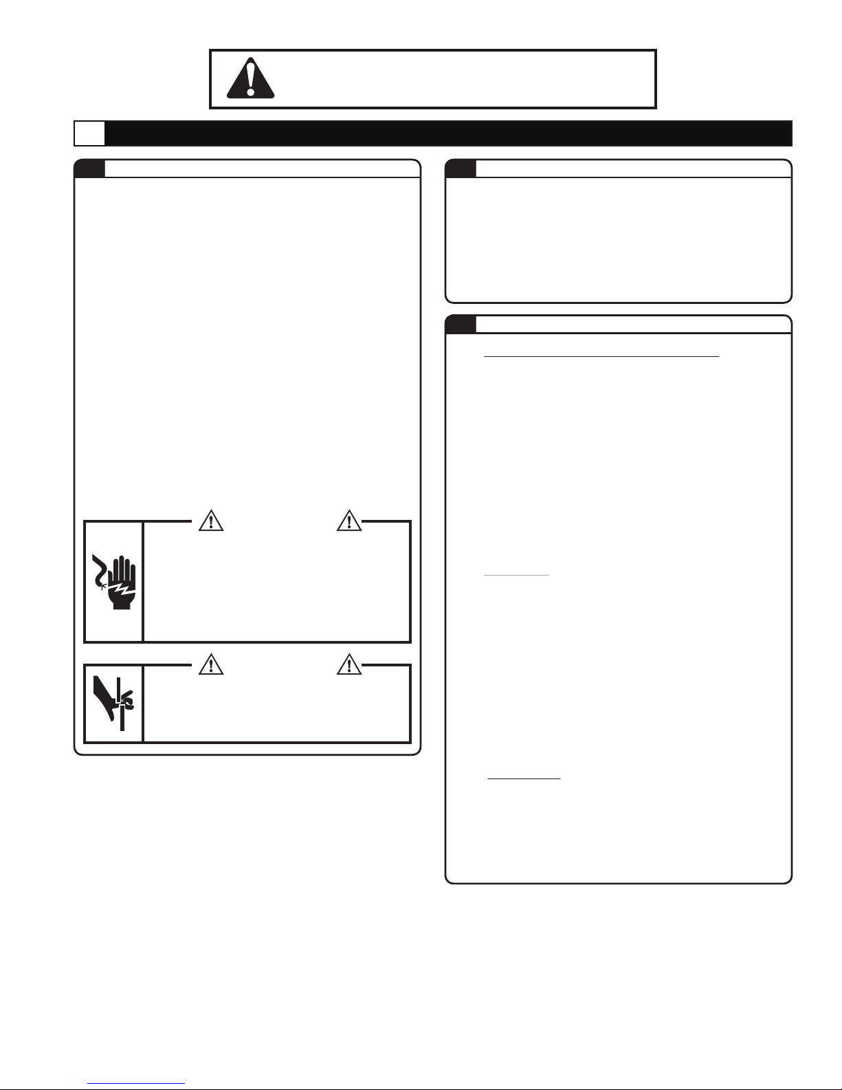
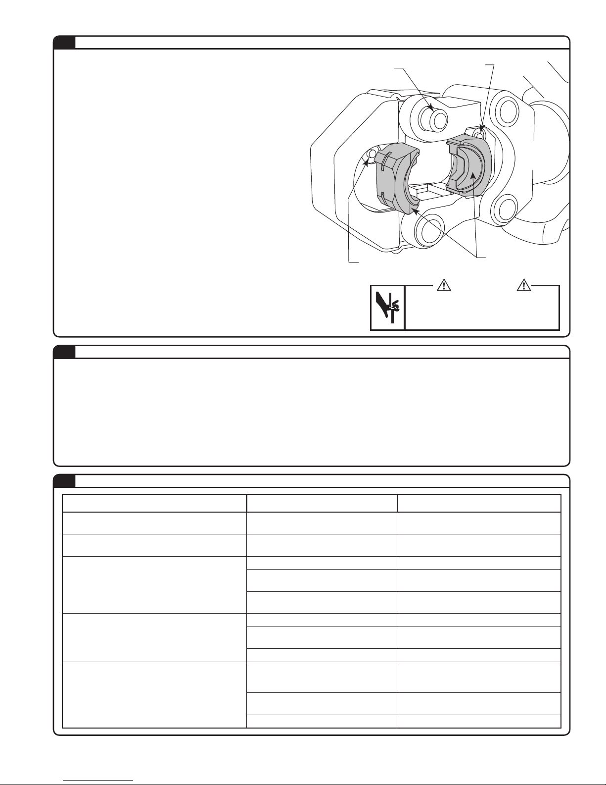
4.1 PRECAUTIONS FOR COMPRESSION TOOL
1. Select the approproiate dies for the connector and
conductor to be compressed. Incorrect combinations
result in inferior connections of the conductors.
2. Never operate the tool without dies installed.
3. Always point the tool away from other people.
4. If the tool is stored for an extended period at a
temperature of less than 25º F (-5º C), the tool should be
allowed to return to room temperature to ensure smooth
operation. Use the tool only after it has been at room
temperature for 1 hour.
5. Do not drop the tool. Dropping the tool may damage the
hydraulic circuit and cause malfunctions.
6. Keep the head and ram clean and free of debris. Solvents
can be used to clean the head but should not be used on
the plastic body. Use soap & water to clean the body.
PRECAUTIONS FOR THE BATTERY PACK
4.2
1. Do not short circuit the contacts or expose the battery to
water, oil or solvents.
2. Do not disassemble or attempt to repair the battery or
dispose of in a re.
3. Do not drop or otherwise abuse the battery.
4. Do not leave the battery in locations where it will be
exposed to a temperature greater than 104 degrees F (40
degrees C) for an extended period.
5. The battery has a limited life. When the capacity
becomes about 1/2 that of the original capacity, the
battery should be replaced.
6. If the battery is stored without being charged, natural
drainage will cause the power to be reduced. The battery
should be charged every 3 months if not in use regularly.
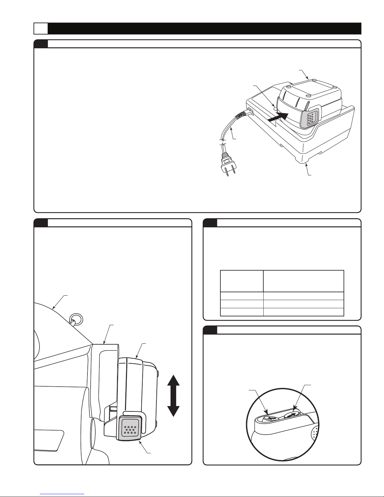
PRECAUTIONS FOR THE CHARGER
4.3
1. The LED lamp lights up green and remains lit when the
unit starts charging a battery. The indicator turns orange
when charging is completed.
2. This unit is for charging battery 144-BAT-LI only. Do not
use the charger for any other devices.
3. Allow battery cartridges to cool before charging. Allow at
least 15 minutes between charges when charging several
batteries in succession.
4. Charge batteries at an ambient temperature of 50-95
degrees F (10-35 degrees C). Charging time is
approximately 25 minutes for 80% capacity and 45
minutes for 100% capacity.
5. Never short circuit the output contacts.
6. Do not expose the charger to water, oil or solvents.
7. Do not disassemble, modify, drop or otherwise abuse
the charger.

TBM15CR-LI PARTS DIAGRAM
5.1
5.0 PARTS BREAKDOWN
TA04721 B Page 7 of 8

TA04721 B Page 8 of 8
Thomas & Betts Corporation
Memphis, Tennessee
www.tnb.com
© 2017 Thomas & Betts. All Rights Reserved.
TBM15CR-LI PARTS LIST
5.2
NO. DESCRIPTION CODE QTY.
11 M4 X 15 SCREW R150-01 10
12 HOUSING (R) 351-01 1
13 CONTROL UNIT 351-02 1
15 BINDER HR-30 3
16 HOUSING (L) 351-03 1
17 HANGING RING ASS’Y ROB-101A 2
18 4 X 12 PARALLEL PIN 351-04 2
19 OIL FEED CAP 351-05 1
20 CARTRIDGE CAP ROB-103 1
21 SWITCH KNOB 351-06 1
22 RELEASE UNIT 351-07 1
23 M4 X 10 SCREW 351-08 2
24 M4 FLAT WASHER 16-81 6
25 M2.3 X 25 SCREW ROB-86 2
26 M2.3 HEX NUT P500-22 2
27 POWER UNIT 351-09 1
28 M4 X 14 SCREW ROB-128 4
29 RESERVOIR CAP 410-55 1
30 MAGNET ROB-25 1
31 OIL RESERVOIR (37) 351-10 1
32 P-40 O-RING 700S-27 1
33 SI-20 RING 410-74 2
34 FILTER SCREEN 410-73 2
35 STRAINER 9H-43A 2
36 STRAINER BUSHING (1) 351-11 1
37 COPPER GASKET (20) 100W-17 1
38 3/16” BALL 16-49 4
39 SPRING (340) 51-27 1
40 STRAINER BUSHING (2) ROB-82 1
41 M5 X 5 SCREW (F.P.) 510A-05 3
42 5/32” BALL 22-21 4
43 3 X 8 DOWEL PIN (D) 610F-11 3
44 PS-8 PENT SEAL 16-44 2
45 P-8 BACK-UP RING (B.C.) 85-33 2
46 7/32” BALL 16-26 1
47 M3 FLAT WASHER 16-38 1
48 SPRING (76) 16-39 1
49 9/32” BALL 16-40 3
50 M10 X 12 SCREW (F.P.) 40-47 1
51 RELEASE PIN 351-12 1
52 P-3 O-RING 16-36 1
53 VALVE CARTRIDGE R510-18B 1
54 S-9 O-RING 410-71 1
55 P-8 O-RING (B) 700S-15 1
56 M5 X 5 SCREW 300-73 1
57 VALVE SCREW (4) 351-13 1
NO. DESCRIPTION CODE QTY.
58 SPRING (595) 351-14 1
59 REDUCTION VALVE 351-15 1
60 P-5 BACK-UP RING (B.C.) E3-126 1
61 P-5 O-RING 5N-35 1
62 SPRING (371) 51-17 1
63 STOPPER PIN 351-16 1
64 BODY 351-17 1
65 SPRING (66) 85-40 2
66 SPRING (67) 85-39 2
67 VALVE SCREW (2) 351-18 1
68 SPRING (340) 51-27 1
69 VALVE SCREW (3) 351-19 1
70 P-7 O-RING 16-60 2
71 VALVE SCREW (1) R510A-09 1
72 S-5 O-RING 351-20 1
73 INNER PIPE 351-21 1
74 P-44 O-RING 610-14 1
75 P-44 BACK-UP RING (B.C.) 610-13 1
76 P-20 BACK-UP RING (B.C.) 35-18
1
77 P-20 O-RING 410-34 1
78 RAM 361-03 1
79
DIE HOLDER RETAINER SCREW
3610-104 2
80 SPRING (622) 361-04 1
81 BODY HEAD 361-05 1
82 4 X 25 DRIVE PIN 30-03 2
83 PIN (122) 361-06 3
84 CE-14 SNAP RING 12K-11 6
85 SER-30 SCRAPER R510-03 1
86 TOOL JAW 361-07 1
87 DIE RELEASE PIN (B) 410-14 2
88 2.5 X 14 DRIVE PIN (AW) 510-10 1
89 SPRING (177) 410-01 2
90 RETAINER PIN (B) 410-12 2
91 2.5 X 10 DRIVE PIN (AW) 22-05 1
92 SIDE YOKE 361-08 1
93 LATCH 361-09 1
94 SPRING (140) 55A-04 1
95 STOPPER PIN 130D-09 1
96 LOCK PIN 361-10 1
97 YOKE 361TB-11 1
98 RETAINING SCREW 361TB-04 1
99 HEAD COVER 3610-101 1
100 YOKE COVER 3610-103 1
101 RUBBER CAP 3610-102 1
271 PUMP PISTON (2) P500-10 2
Table of contents
Other blackburn Power Tools manuals
Popular Power Tools manuals by other brands

Multipick
Multipick KRONOS instructions

Master Appliance
Master Appliance Heat Gun HG-501A-D Specifications

SKS Germany
SKS Germany AIRBOY CO2 manual

Ryobi
Ryobi RY18PCA Original instructions

Ingersoll-Rand
Ingersoll-Rand R3000 Series Product information

Harnisch+Rieth
Harnisch+Rieth D-H 22 S operating instructions