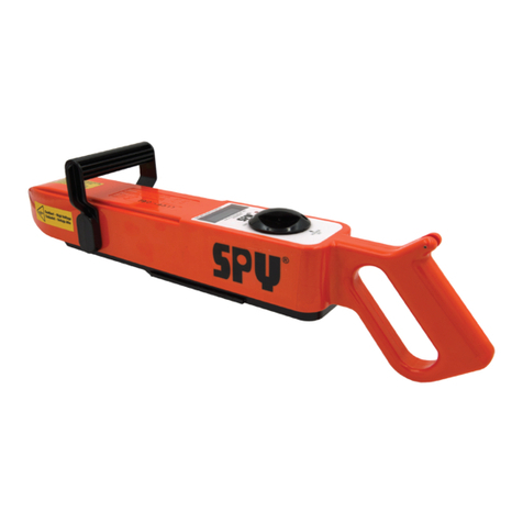
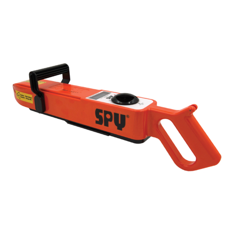
SPY 785 User manual

o p e r at i n g
instructions
Spy®
portab le
pulse
dc
h o l i day
detector
model
785 / 790

2
welcome
Thank you for purchasing the SPY®Model 785 / 790 Pulse DC Holiday
Detector.
SPY Inspection Equipment and our SPY®brand of Coating Inspection,
JeepMeter and Pig Tracking equipment has been serving companies
all over the world since 1953. With the purchase of this high precision
instrument you can now enjoy access to worldwide service and support
only SPY®and our vast Distributor network can offer.
For more information about SPY®brand equipment please visit our
website at www.spyinspect.com.
The SPY®Model 785/ 790 meet the Electromagnetic Compatibility
Directive and the Low Voltage Directive. The product is Class A,
Group 1 ISM equipment according to CISPR 11. Group 1 ISM product:
A product in which there is intentionally generated and/or used
conductively coupled radio-frequency energy which is necessary for
the internal functioning of the equipment itself. Class A products are
suitable for use in all establishments other than domestic and
those directly connected to a low voltage power supply network
which supplies buildings used for domestic purposes.
is a registered trademark of SPY Inspection Equipment,
Houston, Texas, United States.
A copy of this Operating Instructions Manual can be downloaded on our
website at www.spyinspect.com.

3
Ta b l e
of
contents
Operator Safety . . . . . . . . . . . . . . . . . . . . . . . . . . . . . . . . . 4
Unit Calibration . . . . . . . . . . . . . . . . . . . . . . . . . . . . . . . . . 6
Principles of Holiday Detector Operation . . . . . . . . . . . . . . 7
SPY®Model 785/ 790 Pulse DC Holiday Detector Overview . . . . . 8
Connecting Accessories . . . . . . . . . . . . . . . . . . . . . . . . . . 10
Grounding Methods . . . . . . . . . . . . . . . . . . . . . . . . . . . 12
Controls and Voltage Adjustments . . . . . . . . . . . . . . . . . . . 20
Test Voltage Guide . . . . . . . . . . . . . . . . . . . . . . . . . . . . 22
DC Paddle . . . . . . . . . . . . . . . . . . . . . . . . . . . . . . . . 23
Battery Charging & Storage Instructions . . . . . . . . . . . . . . 24
Field Calibration . . . . . . . . . . . . . . . . . . . . . . . . . . . . . . . . 26
Troubleshooting Guide . . . . . . . . . . . . . . . . . . . . . . . . . . 27
Maintenance and Repair . . . . . . . . . . . . . . . . . . . . . . . . 29
Technical Specifications . . . . . . . . . . . . . . . . . . . . . . . . . 30
Warranty . . . . . . . . . . . . . . . . . . . . . . . . . . . . . . . . . 31
Electrode Types . . . . . . . . . . . . . . . . . . . . . . . . . . . . . 32
Accessories . . . . . . . . . . . . . . . . . . . . . . . . . . . . . . . . . . 33
Related Equipment . . . . . . . . . . . . . . . . . . . . . . . . . . . . 34

4
operator
safety
PLEASE READ THESE INSTRUCTIONS CAREFULLY PRIOR TO
USING THE EQUIPMENT!
WARNING! This is a HIGH VOLTAGE device capable of producing an
electrical shock if not properly grounded and/or operated in accordance
with the instructions and procedures prescribed in this manual! If you have a
pacemaker or other life critical electronic medical device DO NOT use this device.
Only trained and responsible personnel should operate high voltage equipment.
Display warning labels prominently prior to and during testing. Portable holiday
detectors are designed to operate and maintain an electric current output well
below levels which could cause injury. However, you may experience a mild shock
if the test electrode or ground is touched while the equipment is activated. Wear
rubber or plastic gloves and non-conductive footwear to minimize potential shock.
Keep in mind that the shock prevention effectiveness of the rubber or plastic glove
and footwear is limited to the condition of their protective surface. Make sure your
gloves and footwear are void of tears and holes and are in good condition.
Use of Portable Holiday Detectors is limited to finding defects in insulating
materials. Testing should be conducted clear of personnel not involved in the
testing procedure. Personnel operating Portable Holiday Detectors should
be aware of the safety limitations imposed by their environment at all times.
Operator should have an assistant to ensure that unauthorized personnel are
kept clear of the testing area.
DANGER! Portable Holiday Detectors create an arc or spark. Use of
a Portable Holiday Detector in or around combustible or flammable
environments can result in an explosion. When operating in any potentially
hazardous area, consult with the plant or site safety officer before proceeding
with a holiday detection test in any potentially hazardous or suspect area.
DANGER! IF YOU HAVE A PACEMAKER DO NOT USE THIS
DEVICE.

5
DO NOT CUT THE GROUND CABLE TO A SHORTER LENGTH.
CAUTION! DO NOT TOUCH THE BARE GROUND WIRE WHEN
THE DETECTOR IS TURNED ON.
WARNING! DO NOT USE WHEN RAINING. If it is raining then
there is a safety concern for the operator. Pure water is non-
conductive, but almost any contaminant will cause water to become conductive
(dust in the air or salt from an operator’s hands). If conductive water covers the
wand (the black plastic part of the detector where the electrode is attached) and
the orange case then the operator will become the return path for the high
voltage. While this is NOT LETHAL, it does hurt. Also the unit may become
damaged.
If it isn’t raining, but the coating surface is wet, the problem becomes one
of accurately locating the coating defect (holiday). Again, the water will
conduct the electricity and you may get false holiday indications many feet from
the actual holiday(s). In this case it is recommended that you dry the testing area
prior to inspection.
CAUTION! DO NOT USE AROUND SENSITIVE
ELECTRONICS OR RADIO EQUIPMENT. When in standby the
SPY®Model 785 / 790 Pulse DC Holiday Detector will generate radio frequency
emissions which are within the limit defined by the Electromagnetic Compatibility
Directive. Due to its method of operation however, the SPY®Model 785 / 790
Pulse DC Holiday Detector will generate broadband RF emissions when the unit is
generating high voltage or when a spark is produced at the electrode. It is therefore
recommended that the user does not activate the high voltage within the vicinity
of sensitive electronics or radio equipment.
ELECTRODES / ACCESSORIES: It is imperative for the accurate operation of
the unit that electrodes (Spring & Brush) and accessory attachments (Spring &
Brush Wands & Ground Cable) be kept clean and free of dirt and debris. Please
clean with a damp cloth before storing them for future use.

6
unit
calibration
As the operator of this unit you require accurate, safe, and reliable equipment to
perform coating inspections at the proper output voltage.
Prior to leaving our manufacturing facility SPY Inspection Equipment certifies that
SPY®Model 785 / 790 Holiday Detector has been calibrated and demonstrates
the output voltage, which appears on the display of the detector within +/- 5% of
indicated setting over the range of 1-15 kV for the 785 and 5-35 kV for the 790.
Since output voltage is regulated, this tolerance is maintained regardless of load.
Your unit comes with a Factory Calibration Certificate Traceable to NIST and a
Factory Authorized Calibration Decal applied to the side of the unit both with
the date your unit was calibrated.
Our units do not tend to drift but it is recommended that this unit be calibrated at
least once per year or more frequently based on heavy usage. Recalibration of
our equipment should be performed ONLY at a SPY®Authorized Service
Center due to the unique calibration process; test equipment utilized and
properly trained SPY®technicians.
We DO NOT recommend using any other calibration service other than a SPY®
Authorized Service Center; using an outside service with technicians not trained
to work on SPY®brand equipment could damage the unit and, if the enclosure is
opened, void the warranty.
When equipment service is needed please visit our Services & Repairs page on
spyinspect.com.
Fill out the online service form, submit, and then follow the instructions provided
in the confirmation email that is sent to you. Please check your spam folder if
you do not get the confirmation email. If you experience issues with the online
service form please call us at 713-681-5837 so we can assist you.
For International Customers we have Authorized Service Centers World Wide.
Please visit the Distributor Locator page on spyinspect.com to search for a local
SPY®Authorized Service Center in your area. If none, please see instructions
above to send to our SPY®Manufacturing Facility.

7
principles
of
h o l i day
detector
operation
Holiday detectors are devices that are used to detect the presence of
defects in the non-conductive coatings applied to surfaces in order to
minimize ion flow from a conductive substrate. This is accomplished
by attempting to create an electrical circuit by passing an electrode
over the non-conductive coating. A sufficient voltage is generated in
the electrode to cause a spark that will jump from the electrode to the
substrate if a defect is found. When a defect is found a horn will sound
and a LED light will turn off.
Metal objects such as pipelines, reinforcing bar (rebar), storage tanks
or structural steel are normally covered with a protective coating to
prevent corrosion. Holiday detectors are used to inspect these coatings
for pin holes, scratches or other coating faults. They work by generating
a voltage high enough to jump a gap that is longer than the thickness of
the coating.
The laws of physics determine the required voltage level to jump a given
distance, or gap. Coating type also affects voltage level requirements.
Environmental Conditions such as humidity, temperature, and other
environmental factors will also affect voltage required to jump a given
distance.
A holiday detector simply applies a voltage to the outside of the coating.
With the pipe connected to ground and with the holiday detector
connected to ground, a hole in the coating will allow a spark to jump
or “arc” from the electrode to the pipe to complete the circuit. When a
complete circuit is formed, an audible and visual signal is activated on
the holiday detector.

8
spy®
model
785 / 790
pulse dc
h o l i day
detector
overview
The Model 785 Pulse DC Holiday Detector is a high voltage (1-15
kV) detector designed to cover a wide range of coatings from thin
films to tapes to extruded or coal tar types of coatings (4 -150 Mils).
Since the operating characteristics of this detector are very broad it
is recommended that thin film epoxy coatings be inspected with the
model 780 or 785 holiday detector.
The Model 790 Pulse DC Holiday Detector is a high voltage (5-35 kV)
detector designed specifically for tapes, extruded or coal tar types of
coatings, and thicker somatic type coatings (50 -750 Mils).
The Model 785 / 790 Pulse DC Holiday Detectors incorporates circuitry
allowing the detectors to maintain a selected voltage, regardless of
different pipe diameters, coating thickness variations and battery wear
(unless the battery is totally discharged). Keep in mind that the voltage
can decrease slightly depending on ground losses and/or conditions.

9
1 Electrode Accessory
Connection Point
2 Electrode Wand
3 Shoulder Strap Connection
4 Easy Carry Top Handle
5 Model & Serial Number
6 Built In Digital LCD JeepMeter
(Voltage meter)
7 Indicator Light
8 Control Knob (3 positions:
Off / Voltage Set / On)
9 Voltage Set Access Hole
10 Shoulder Strap Connection
11 Comfort Grip
12 Ground Cable Connection Point
13 Horn
14 Quick Release Battery Button
15 12V Battery
16 Wand Release
17 Spring or Brush Electrode
11
12
15
16
2
14
13
6 8
9
4
5
3
10
1
17
7

10
connecting
accessories
CAUTION! DO NOT TOUCH. Make sure the switch is in the OFF position
prior to connecting any accessory.
STEP 1. CONNECTING THE ELECTRODE WAND. Plug into the “front”
of the detector. Push the wand in until it locks in place. It can be released by
pressing the release (located near the front / bottom of the unit) upwards until
the wand pops out.
STEP 2. CONNECTING THE ELECTRODES. Connect the electrode to the
wand. The wand comes with the spring adapter attached to the wand. If it is a
spring or full circle brush electrode attach to the pipe.
CAUTION! DO NOT TOUCH THE ELECTRODE WHILE THE DETECTOR
IS OPERATING.
Battery
Control Knob
Shoulder Strap
Electrode Wand
Caution! - High Voltage
Cuidado! - Voltaje Alto
1 2 3
Clip Installation
1
3
4
5

11
CAUTION! DO NOT TOUCH THE GROUND CABLE WHILE DETECTOR
IS OPERATING.
OPTIONAL: BRUSH ADAPTER KIT. The Model 780 Kit comes with a
brush adapter kit for use in connecting flat brush / neoprene electrodes, half-circle
electrodes and full-circle electrodes.
STEP 3. CONNECTING THE CLIP \ SHOULDER STRAP. First attach the
strap clip to the black handle by placing the tab portion of the strap clip into the
top groove on the back side of the handle that faces the unit display. Then push
up on the bottom of the strap clip in the direction of the opposite side of the black
handle until the strap clip snaps into place around the black handle. Next attach
the shoulder strap to the front handle clip and the pin on top of the rear handle.
The front clip can slide to the left or right on the handle to allow hand placement
while using the detector.
STEP 4. BATTERY. The battery will only install one way (from the front side).
It is keyed to prevent insertion in an incorrect fashion. One end of the battery
is flat and the other has a step. The flat end goes towards the rear of the unit.
Push the battery on until it snaps in place (the spring will be almost completely
compressed when properly installed). To remove the battery, press the orange
release on the bottom left side of the unit. Newer batteries can be a bit resistant
when trying to remove the battery because of the newness of the battery and
the tight fit on the slide path; if so give a gentle tap with your palm on the battery
in the direction of removal.
STEP 5. CONNECTING THE GROUND CABLE. The ground cable plugs
into the bottom side of the rear handle. It uses a quarter turn fastener, so insert
the cable as far as possible and rotate it at least a quarter clockwise turn until it
locks into place. The kit includes a quick connect grounding clamp that allows
the option to take the clamp on or off the ground wire for different grounding
methods. Earlier kit versions did not include a grounding clamp and you can order
one from SPY if you would like the ability to add one to your ground cable.
PROPER GROUNDING. Make sure the ground cable is uncoiled and
extended.

12
Grounding methods
1. DIRECT GROUNDING
Direct grounding using the standard 50 ft ground cable is the most reliable form
of grounding which offers a direct connection between the holiday detector
and the non-insulated pipe end (cut back) to be tested.
A. Part #12884 50 ft ground cable
Optional Parts needed to ground using this method:
B. Part #14196 Grounding Rod

13
An additional grounding rod allows the direct grounding of the holiday detector,
if the bare pipe end (cut back) cannot be connected using the standard 50 ft
ground cable. If desired SPY®also makes custom length ground cables of
any length, contact sales for details. Refer to the Grounding Methods on
page 16 for more details.
A. Part #12884 50 ft ground cable (custom lengths available)
Optional Parts needed to ground using this method:
B. Part #14196 Grounding Rod
2. DIRECT GROUNDING USING A SECOND GROUNDING ROD

14
3. INDIRECT GROUNDING USING A TRAILING GROUND WIRE
Indirect grounding using a trailing ground. This grounding alternative allows
holiday testing without an obstructing cable, if direct grounding is not possible.
To use the ground cable using the trailing ground method please remove the
quick connect grounding clamp if you have it attached, to keep it clean so it
makes good ground connection when needed (some earlier kit versions may
not have this kit part).
IMPORTANT: Soil Moisture is very important to establishing a good ground
using the trailing grounding method, if the trailing ground wire is on soil that is
too dry, there is ice or it is on cement this method will not work properly and
the trailing ground will need to be connected to a grounding rod. Refer to the
Grounding Methods on page 16 for more details.
A. Part #12884 50 ft ground cable (custom lengths available)
Optional Parts needed to ground using this method:
B. Part #14196 Grounding Rod

15
4. CAPACITIVE GROUNDING USING A GROUNDING COLLAR
The grounding collar is used if no direct or indirect grounding is possible. The
grounding collar is also recommended in case of bad conducting or extremely
dry soil. Refer to the Grounding Methods on page 16 for more details.
A. Part #12884 50 ft ground cable (custom lengths available)
Optional Parts needed to ground using this method:
B. Part #14196 Grounding Rod
C. Part #14188 Grounding collar 4”- 8”
Part #14189 Grounding collar 10” - 18”
Part #14190 Grounding collar 20” - 30”
Part #14191 Grounding collar 32” - 42”
Part #14192 Grounding collar 48” - 60”
FOR USE ONLY WITH 785/790 AND 125/135 PULSE DC UNITS

16
Grounding methods
EARTH (SOIL) GROUND AS AN ELECTRICAL CURRENT RETURN PATH
For a Holiday Detector to inspect a coated pipe properly an electrical ground
return path is needed. When a holiday in the coating is detected a spark occurs
forcing a low current to flow from the metal pipe back through the ground wire
of the detector. An alarm circuit inside the detector senses the low current and
a “JEEP” is heard.
The most optimum electrical ground return path is with the ground wire of
the Holiday Detector directly connected to the bear pipe end, “cutback”. This
method is called “Direct Grounding”. Using this method, the low current flows
through a wire of very low resistance back to the detector. In this case the
Earth is not part of the ground return path.
In many instances Direct Grounding is not possible. Two alternate methods
can be used, “Direct grounding using a secondary ground rod” or “Indirect
grounding using a trailing ground wire”. In both methods the Earth (soil) now
becomes part of the electrical ground return path allowing the low current to
flow back to the detector.
In all cases, for the safety of all personnel during the coating inspection, the
pipe should be grounded to Earth. Make an electrical connection to the bear
end of the pipe, “cutback”. Attach a wire from this connection to a ground rod
driven into the Earth. Depending on the moisture content of the soil the ground
rod should be driven down about 2 feet. Drive the rod deeper in dryer soils.

17
GOOD GROUNDING PRACTICES
Soil conditions must be evaluated prior to beginning the job
1. Soil Moisture Content
Since the Earth is being used as an electrical conductor the moisture content
of the soil must be taken into consideration. Soils with a high moisture
content offer a lower resistance to current flow and have a much lower
voltage loss. While soils of a low moisture content offer a higher resistance
to current flow, there is a greater voltage loss.
The voltage loss that is referred to here, exists between the ground rod
where the pipe is grounded to Earth and the ground rod or trailing wire where
the Holiday Detector is grounded to Earth. This distance could be 35 – 50
feet or even several 1000 feet depending on the job conditions.
As an example, if the job was located in an area of low soil moisture content,
called for an inspection voltage of 2.5KV and there happened to be a voltage
loss of 1.5KV between ground rods, the Holiday Detector would have to
be adjusted to 4KV to compensate for the 1.5KV loss in the Earth and yet
maintain the 2.5KV between the pipe and the coating. The 4KV voltage
setting would have been identified by performing a “Field Calibration”.
In this example, refer to illustration #3, avoid using the “Indirect grounding
using a trailing ground wire” method. This method allows the ground wire to
only come in contact with the surface of the soil. No ground rod is used to
locate an area of higher soil moisture content.
2. “Insulating” Surfaces
When the moisture content in a soil is so low it can’t provide the low resistance
return path for the low current and it basically becomes an “insulator” with
very high resistance and higher voltage loss.
For example, if the soil is very dry with low moisture content such as sand,
dry clay or a rocky surface, when the soil is frozen or there is ice on the
surface, these surfaces have become “insulators” and can’t provide a low
resistance return path. Other “insulating” surfaces would be concrete,
cement and asphalt. In each instance there would be a significant voltage
loss in the soil.

18
GROUND ROD DEPTH BECOMES AN ISSUE WHEN PROVIDING A GOOD
EARTH GROUND
1. Shallow Ground Rod
When the moisture content of the soil is high a ground rod can be driven
into the earth about 1 - 2 feet to provide a low resistance return path to the
holiday detector.
2. Deep Ground Rod
When the moisture content is low the ground rod needs to be driven down
deeper into an area where a higher soil moisture content exists. Driving the
rod deeper helps to reduce the voltage loss in the Earth. Both ground rods,
at the cutback end of pipe and where the Holiday Detector is connected,
typically are driven to the same depth and could be up to 5 feet deep or
greater, in some areas. Soils of this type would be sand, dry clay or very
rocky soils.
PERFORM FIELD CALIBRATIONS TO MAINTAIN A GOOD GROUND
THROUGHOUT THE JOB
SPY®highly suggests performing a Field Calibration at the beginning of the
job, at certain intervals during the job, if the soil moisture content becomes
questionable and when changing locations on the same job.
Field Calibration:
When the moisture content of the soil is high a ground rod can be driven
into the earth about 1 - 2 feet to provide a low resistance return path to the
holiday detector.
• How to perform a Field Calibration can be found in NACE SP0490-2007,
Section 3.
• Per section 3.3.1, create a holiday that is approximately 0.031” in diameter.
Ensure that the hole extends completely through the coating to the metal
substrate.
• Per section 3.3.2, start with the lowest test voltage setting of the holiday
detector and slowly increase the test voltage until the manufactured
holiday can be positively detected at normal operating speeds.
• Per section 3.3.3, this method of test voltage adjustment shall be performed
while the exploring electrode and grounding are in the expected operating
position.

19
For example, when inspecting a good distance of welded pipeline, it would
be advisable to perform Field Calibrations at certain intervals along the
pipeline to verify a known holiday can still be easily detected at the specified
inspection voltage. This will assure the operator that he is inspecting the pipe
under optimum conditions and is not missing any holidays. A Field Calibration
would also allow the operator to make any voltage adjustments to the Holiday
Detector to compensate for any voltage loss in the soil between ground rods,
if conditions do change.
CONSIDERATIONS – ‘’INDIRECT GROUNDING USING THE TRAILING
GROUND WIRE’’ METHOD
This grounding alternative, Illustration #3, allows holiday testing without an
obstructing cable, if direct grounding is not possible.
Important: When using this method “Soil Moisture Content” is very
important to establish a good ground. The moisture in the soil acts as a return
path for a low current that flows back to the holiday detector allowing the unit
to “Jeep” when a holiday is located. Without this low resistance return path,
the unit would not Jeep and the operator would miss valid holidays.
Caution: This method should not be used when a surface becomes an
“insulator” and can’t provide a low current return path.
For example, if the soil is very dry with low moisture content such as sand, dry
clay or a rocky surface, when the soil is frozen or there is ice on the surface.
these surfaces have become “insulators”. DO NOT use this method when the
trailing ground must be dragged across concrete, cement or asphalt surfaces.
These too are considered “insulating” surfaces.
CONSIDERATIONS – ‘’CAPACITIVE GROUNDING USING A GROUNDING
COLLAR’’ METHOD
This grounding method, Illustration #4, can be used only with Pulsed DC
holiday detectors such as the SPY 785 or 790. It cannot be used with the SPY
780 detector since it has a continuous DC voltage output. The DC low current
that would normally be produced when a holiday is located is blocked by the
capacitance of the grounding collar. Therefore, no holidays can be detected.

20
controls
and
vo ltag e
adjustments
The control knob has three positions: OFF, VOLTAGE SET, and ON.
In the OFF position all power is off, including the high voltage output.
STEP 6. SETTING THE VOLTAGE OUTPUT. Turn the knob
clockwise to the middle position (voltage set) this turns on the high
voltage output and activates the internal JeepMeter (voltage meter), the
LCD display turns on, the red indicator LED light will blink and the horn
tone will pulse on and off.
Using the SPY®provided flathead screwdriver place the flat screwdriver
head through the hole on the bottom side of the knob to change
the voltage setting,the voltage (shown on display) is in kilovolts
(thousands of volts). Turning the screwdriver clockwise will increase the
voltage and counter clockwise will decrease the voltage.
POWER ON
RIGHT
POWER OFF
LEFT
VOLTAG E SET
MIDDLE
Other manuals for 785
1
This manual suits for next models
2
Table of contents
Other SPY Security Sensor manuals

