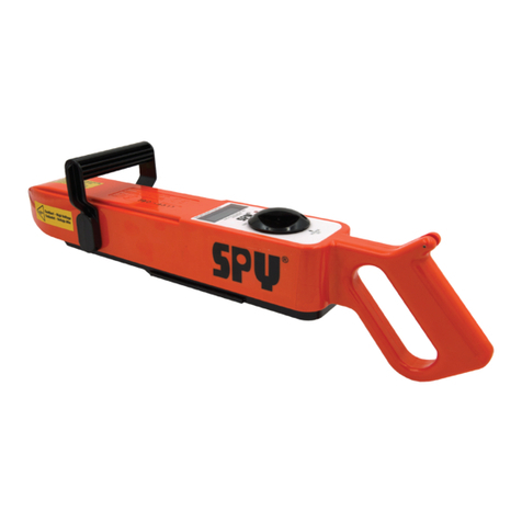
SPY 780 User manual

PIPELINE
INSPECTION
COMPANY
LTD.
Portable Holiday Detectors
OPERATING
INSTRUCTIONS
SPY
®
‚PORTABLE
HOLIDAY DETECTORS
Models 780, 785, & 790

2
Safety Disclaimer
Only trained and responsible personnel should operate high
voltage equipment. Display warning labels prominently prior to and
during testing. Portable holiday detectors are designed to operate
andmaintainanelectriccurrentoutputwellbelow levels whichcould
cause injury. However, you may experience a mild shock if the test
electrode or ground is touched while the equipment is activated.
Wear rubber or plastic gloves and non-conductive footwear to
minimize potential shock. Keep in mind that the shock prevention
effectiveness ofthe rubber orplastic glove and footwear islimited to
the condition of their protective surface. Make sure your gloves and
footwear are void of tears and holes and are in good condition.
Use of Portable Holiday Detectors is limited to finding defects in
insulating materials. Testing should be conducted clear of personnel
not involved in the testing procedure. Personnel operating Portable
HolidayDetectorsshouldbeawareofthesafetylimitationsimposedby
their environment at all times. Operator should have an assistant to
ensurethat unauthorizedpersonnelare kept clear of the testingarea.
Danger: Portable Holiday Detectors create an arc or spark. Use
of a Portable Holiday Detector in or around combustible or
flammable environments can result in an explosion. When operating in
any potentiallyhazardousarea, consultwiththeplant or site safetyoffi-
cer before proceeding with a holiday detection test in any
potentiallyhazardousorsuspectarea.
EMI Disclaimer
WARNING....This is a class A product. In a domestic environment
this product may cause radio interference in which case the user may
berequired totake adequate measures.
NOTE....
Holiday detectors create a spark during their normal course
of operation when a defect in the pipe coating is found.
This spark will cause radio interference. During the device’s passive
or search mode, it qualifies as a class A product.

3
Table of Contents
Safety & EMI Disclaimer .............................. 2
Principles of Operation................................. 4
Differences Between Models......................... 5
Operating Instructions .............................. 6-8
Battery Instructions ..................................... 9
EC Declaration of Conformity...................... 10
Warranty................................................. 11
Warning! This is a HIGH VOLTAGE device capable of
producing an electrical shock if not properly grounded and/or
operated in accordance with instructions and procedures
prescribedinthismanual!

4
Principles of Operation
Metal objects such as pipelines, reinforcing bar (rebar), storage
tanks or structural steel are normally covered with a protective
coating to prevent corrosion. Holiday detectors are used to inspect
these coatings for pin holes, scratches or other coating faults. They
work by generating a voltage high enough to jump a gap that is
longer than the thickness ofthe coating.
The laws of physics determine the required voltage level to
jump a given distance, or gap. Coating type also affects voltage
level requirements.
A holiday detector simply applies a voltage to the outside of the
coating. With the pipe connected to ground and with the holiday
detector connected to ground, a hole in the coating will cause a
spark to jump or “arc” from the electrode to the pipe to complete the
circuit. When a complete circuit is formed, a signal is activated on the
Holiday Detector.
AbriefdescriptionofthestepsnecessarytooperateaSPY®‚Model
780, 785 or 790 holiday detector is presented here with detailed
steps following later in the manual.
To operate the detector,make sure the control switch is in the OFF
position (fully ccw), then install the battery. The battery is keyed so it
can only be installed in one way. Then install the electrode wand on
the front of detector and insert the ground cable into the rear
of detector (inside handle). Ground the pipeline and connect the
electrode, spring or brush. Turn the control knob to the middle posi-
tion (set voltage). This activates the internal Jeepmeter. A pulsing tone
and light warn that this is the “set voltage” mode. Set the voltage to
the required value. Turn the unit on (fully cw). A running tone and
light indicates the detector is operating. Roll the spring toward the
bare metal end of the pipe. When the electrode is sufficiently close,
a spark will jump from the electrode tothe pipe, the running tone and
light will go out, and a loud signal horn will sound to designate a
holiday. Of course it is not a real holiday but it demonstrates what
happens when the electrode encounters a holiday and verifies correct
detector operation.

Differences between 780, 785, & 790
Model 780, 785, and 790 holidaydetectors incorporate new
circuitryallowing the detectors to maintain a selected voltage,
regardless of different pipe diameters, coating thickness variations
and battery wear (unless the battery is totally discharged). Keep in
mind that the voltage the coating actually “sees” will decrease
slightly depending on ground losses and/or conditions.
The model 780 holiday detector is a low voltage (1-5kv) detector
designed specifically for thin film epoxy coating.sThe output voltage of
this detector is normally D.C. (direct current). However, if moisture is
encountered on the pipe, the detector output automatically switches
to a fast pulse. Fast pulse enables continued operation whereas
with older type thin film detectors the operator either had to wait until
the moisture evaporated or the pipe had to be dried.
The model 785 holiday detector is a high voltage (1-15kv)
detector designed to cover a wide range of coatings from thin films to
tapes to extruded or coal tar types of coatings. Since the operating
characteris- ticsof thisdetectorareverybroadit is recommended
thatthinfilm epoxycoatings be inspected with the model 780
detector.
The model 790 holiday detector is a high voltage (5-35kv)
detector designed specifically for tapes, extruded or coal tar types of
coatings, and thicker somatic type coatings.
780•785•790
5

6
Operating Instructions
Connecting Accessories
The electrode wand plugs into the “front” of the detector. Push the
wand in until it locks in place. It can be released by pressing the release
(located near the “front” of the unit on the bottom) upwards until the
wandpops out.
The ground cable in plugged into the rear handle. It uses a quarter
turn fastener, so insert the cable as far as possible, then rotate
it at least a quarter turn until it locks in place.
Thebatteryinstallsfromthefront.Notethebatterywillonlyinstallone
way - it is keyed to prevent insertion in an incorrect fashion. One end of
thebatteryis flatandthe otherhasa step.The flatendgoestowardsthe
rear of the unit. Push the battery on until it snaps in place (the spring will
be almost completely compressed when properly installed). To remove
the battery, press the release on the bottom left side of the unit (the release
is orangeto stand out against the black base of thedetector).
Electrode wand
connects here
Ground cable
connects here
Battery Slidesthis
direction to remove
Front
Rear

7
Screwdriverhole
Controls
The control knob has three positions: OFF,VOLTAGESET,and
ON.
In the OFF position all power is off, including the high voltage
output. Turningthe knob clockwise 30 degrees to the VOLTAGE
SET position turns on the high voltage output, blinks the red LED,
pulsesthe run tone, and turns on the display. The voltage displayed
is in kilovolts (thousands of volts.) A screwdriver can be placed
through the hole in the rear of the knob nearest the operator to
change the voltage setting. Turning the screwdriver clockwise will
increase the voltage. In the ON position the voltage adjustment is
not accessible. In this position the unit is in the normal running
mode with the red LED on steady, the run tone steady, and the
display off.
CAUTION!
DO NOT TOUCH bare ground wire when the detector is on.
DO NOT CUT the ground cable to a shorter length.

Carrying Strap
CAUTION! DONOTTOUCHtheelectrode or
groundwirewhiledetectorisoperating.
Shoulder strap connection
Spring or brush
electrode connection
Built in Jeepmeter with digital
readout to verifysetting
Easy carry top handle
Positive groundlight
8 hour battery
Toattachthecarrying strap, first snake
the clip under the handle from the front,
insertthetabinto thetopcenter groove on
the front handle, and then snap the clip
around the front handle. The strap is
clipped between the front handle clip and
the pin in the rear handle at thetop.
Comfortable grip
Ground cable enters here
8

Battery Instructions
General : The SPY® battery is a completely sealed, rechargeable
12 volt unit. It can be used in any position and under
most conditions.
To Charge The Battery :
Slide the charger onto the battery as far as possible. The
charger will have an amber LED on while charging. This
LED will be green when charged. A discharged battery
requires 4-8 hours to fully charge.
There is no danger of overcharging the battery. After
the battery is fully charged, the charger will maintain a
trickle charge to keep the battery at peak charge.
It is recommended that the battery be recharged as soon
aspossible after use.
Donotdisconnectthechargepowercordwhilethebattery
is attached.
Battery Storage:
The battery should be fully charged BEFORE storing.
Storage at temperatures below 75˚F is recommended.
After six months of storage or storage in extremely high
temperatures, the battery should be recharged to maintain
peak efficiency and maximize its lifespan.
This Portable Holiday Detector is an accurate, reliable
instrument which is only warranted if it is properly handled,
maintained and operated as prescribed by Pipeline
Inspection Co., Ltd.
BATTERY REMOVAL:
Press the release (orange part) on
the base plate (black part) and push
the battery away from the rear handle.
9
WARNING! Do not use any other type of charger.
This charger is specially designed for this battery .
Battery Release

10
EC Declaration of Conformity
Manufacturer of Equipment:
PipelineInspectionCo.Ltd.
Authorized Representative in the EC Community:
PipelineInductionHeatLTD
ThePipelineCentreFarringtonRoad
Rossendale Road Industrial Estate
Burnley, Lancashire BB11 5SW
England,UnitedKingdom
Attn: Michael Burnley
Description of Equipment:
Holiday Detectors
Models 780, 785, 790 and accessories
Holiday detectors are devices that are used to detect thepresence of
defects in the non-conductive coatings applied to surfaces in orderto
minimize ion flow from a conductive substrate. This is accomplished by
attemptingto createan electricalcircuitby passingan electrodeoverthe
non-conductive coating. A sufficient voltage is generated in the
electrode to cause a spark that will jump from the electrode to the
substrate if a defect is found. When a defect is found a horn will sound
and a light will turn off.
Specifications: The products mentioned above were submitted as
acommonfamilyastheyutilizecommondesigns,componentsandmeth-
odsofconstruction.Representativetestswereperformedoneachdevice
thatwouldexhibitthe“worstcase”scenarioforapproval.

11
Warranty
Pipeline Inspection Co., Ltd., hereafter referred to as (SPY
®
) warrants
that SPY®‚ Model 780/785/790 Series Holiday Detectors and
Jeepmetersshall,undernormaluseand service,be free fromdefectsin
material and workmanship. SPY®‘s entire warranty obligation shall be
limited to, at SPY®'s option, the repair or replacement free of charge to
thebuyerofanydefectiveequipmentorpartsthereofwhichprovetobe
defectivein materialand workmanshipundernormaluseandservice.
Claims for defective parts must be made in writing within twelve
(12) months after shipment of the equipment from the works of SPY
®
.
Fast wearing and consumable parts including, but not limited to,
electrodes and ground cables, are expressly excluded from the
warranty. SPY® shall have the option to require return of a claimed
defective part to SPY®'s plant in the U.S.A., freight prepaid by buyer
for examination to establish buyer's claim.
ExceptwithSPY®'sprior written approval, SPY® shall notbeliable
(a)forthecostofrepairs,alterationsorreplacementsoranyexpense
connected therewith made or incurred bythe buyer or its designers,
or(b)fordefectsresultingfrom alterationsorrepairsmade byothers
than SPY
®
‚or its approved representatives.
SPY® shall not be liable for damages, including but not limited to
direct, special, indirect or consequential, resulting from the handling,
or use, whether alone or in combination with other products, or any
SPY
®
equipment or third party designed or manufactured equipment,
includingwithoutlimitation,anyloss ordamage sustained orcaused
by the operation and use of the equipment which is improperly
operated or its successful operation is impaired by natural elements
afteritsdeliverytothebuyer.
Theforegoingwarrantyisexclusiveandinlieuofallotherwarranties
whether written, oral or implied (including without limitation, any
warranty of merchantability or fitness for purpose).

printed 10.06
Liberty Sales and Distribution, LLC
2880 Bergey Road, Suite F
Hatfield, PA 19440
Phone: (877) 373-0118
Fax: (888) 850-3787
Email: sales@libertysales.net
Other manuals for 780
1
This manual suits for next models
2
Table of contents
Other SPY Security Sensor manuals
