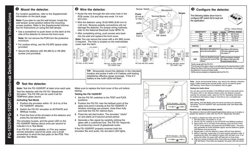
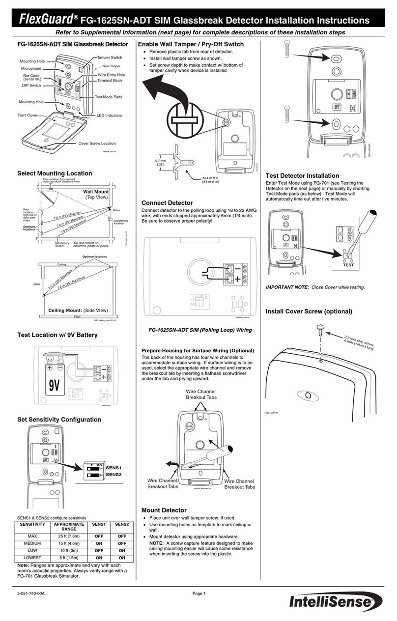
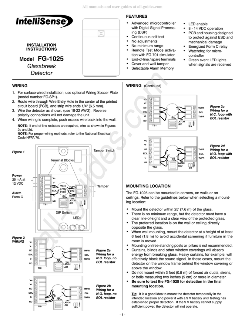
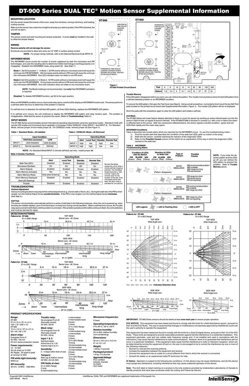
IntelliSense FG-1008 User manual

1
INSTALLATION INSTRUCTIONS
Model: FG-1008
Glassbreak Detector
& Magnetic Contact
MOUNTING LOCATION
The FG-1008 can be mounted on doors
and window frames (indoors only). It can
also be mounted in corners, on walls or on
ceilings. Refer to the guidelines below
when selecting a mounting location.
• Mount the FG-1008 within 8’ (2.4 m) of the glass
to be protected. Do not install beyond this range
even if testing indicates greater range.
• The detector must have a direct line-of-sight to
and a clear view of the glass.
• When wall mounting, mount the detector at a
height of at least 6’ (1.8 m).
• Mountingonfree-standingpostsandpillarsisnot
recommended.
• The FG-1008 will detect through venetian blinds
and light drapes. For heavy window coverings,
mount the unit on the window frame behind the
covering. Test the location thoroughly whenever
there are window coverings present.
• Do not mount the detector within 3 feet (0.9 m) of
forced air ducts, sirens, or bells measuring two
inches (5 cm) or more in diameter.
• Ifthemagneticcontactisenabled,theglassbreak
housing must be mounted less than 1” (2.5 cm)
fromthemagnethousing. The glassbreak detec-
tor and magnet housings must be aligned and
mounted parallel to each other. See Figure 1.
• Magnetically susceptible material will affect the
range of the contact gap. If using the magnetic
contact, be sure to test the gap thoroughly when
mounted on iron or steel surfaces.
• Be sure to test the detector for detection in
the final mounting location.
Mounting Guidelines
TheFG-1008isdesignedtodetectframedglass
broken by an impact sufficient to make a hole.
To minimize the chance of false alarms:
• Avoid installing in rooms with high-level noise
sources, such as air compressors, bells, power
tools, etc., if those sources can be active when
the detector can signal an alarm.
• Testfalsealarmimmunitybyactivatinganyknown
noise sources in the room.
To maximize detection:
• Minimize range to the glass. Do not install be-
yond the maximum specified range, even if test-
ingindicates greater range.
• Verifyallinstallationsbackto the paneltobesure
that the protection loop is intact.
TIP: It is a good idea to mount the detector temporarily in the
intended location and power it with a 9 V battery until testing
has established effective range coverage. If the 9 V battery is
low, it cannot supply sufficient power and the detector will not
operate.
1
STEP1
Figure 1
Carefully push
screwdriver into lower
slot to disengage latch
2
STEP2
Figure 3
Separating the printed circuit board
(PCB) housing from mounting plate
Mount the glassbreak
detector housing and
magnet housing no more
than 1” (2.5 cm) apart.
Glassbreak detector housing
Magnet housing
Figure 2b
Removing the front cover of magnet housing
Magnet housing
back cover
Carefully push
screwdriver into lower
slot to disengage latch Lift up and off
Magnet
Frontcover
Figure 2a
Removing the front cover of glassbreak detector housing
Carefully push
screwdriver into lower
slot and push down to
disengage latch
Tamper armGlassbreak housing
Frontcover Lift up and off
Switch
Magnet

2
3
STEP3
MOUNTING PROCEDURE
IMPORTANT: Test the detector in the desired mounting location
before drilling mounting holes.
1. Toopentheglassbreakhousing,insertascrew-
driverintotheslotattheendofthehousingand
gently depress the front cover latch. Lift and
remove the front cover. Refer to Figure 2a.
2. To remove the front cover of the magnet hous-
ing, insert a screwdriver into the slot at the end
of the back cover and gently depress the front
coverlatch. Liftandremovethefrontcover. Re-
fer to Figure 2b.
3. Separatethemountingplatefromtheglassbreak
housing. Insertascrewdriverintotheslotatthe
topofthePCBasshown. Slightlytwistandgen-
tly push downward on the latch. See Figure 3.
4. Align the “SWITCH” with the “MAGNET” to de-
terminethecorrectorientationformounting. See
Figure4b.
5. Route the wires through the wiring channel as
shown in Figure 4a. (The channel loop forces
condensationoffthewiringandpreventsitfrom
reaching the PCB. ) Remove breakout tab and
useanindustrystandard4” (10 cm)tiewrapifa
strain relief is required.
6. Securethemountingplateandmagnethousing
with #6 (M 3.5) screws (not provided).
7. RemovetheappropriatebreakouttabinthePCB
housing. See Figure 5.
8. Route the wire through the wire entry hole in
the PCB housing and reconnect the housing to
themountingplate.
9. Cutandstripwire ends 1/4” (6.5 mm). Wirethe
detector as shown (use 22 - 18 AWG). Reverse
polarity connections will not damage the detector.
See Figure 5.
10.Replace front cover.
FG-1008 CONFIGURATION
Configure jumpersW1-W3 to best suit the
application. See Figure 6.
W1: The FG-1008 comes with the LEDs
enabled. To disable the LED operation,
remove the jumper from positionW1 on the
PCB.
W2: The detector comes with alarm LED
LATCH disabled. To enable alarm LED
LATCH, place a jumper across W2.
W3: The FG-1008 comes with the mag-
netic contact enabled. To disable the mag-
netic contact, place a jumper across W3.
TESTING
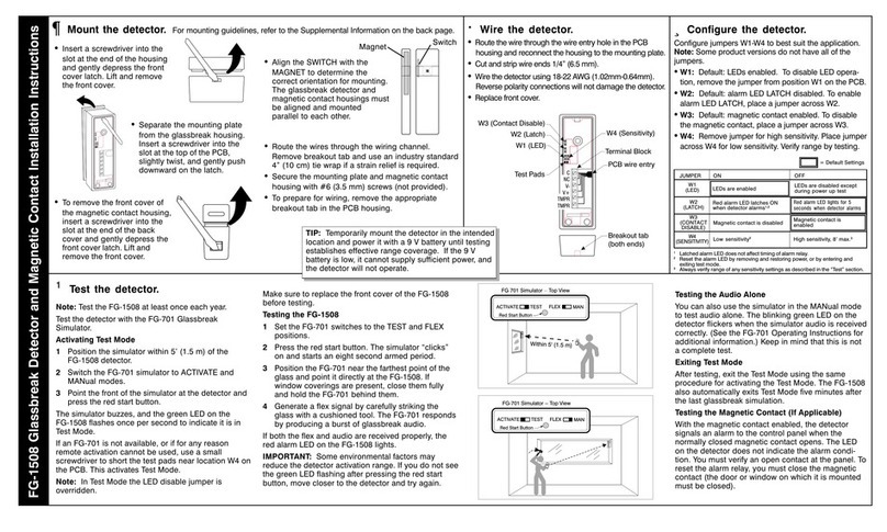
The FG-1008 should be tested at least
once each year. Test the detector with the
FG-701 Glassbreak Simulator. The model
FG-700Glassbreak Simulator can be used
if it is set for the TEMPered glass sound.
Other glassbreak simulators will not give
an accurate indication of range.
You must place the FG-1008 into Test
Mode before you can test the detector.
Figure 4a
Routing the wires through
the mounting plate
Route wire
through wiring
channel and
wire entry hole
of mounting
plate
Wire
entry
hole
MAGNET
Mount the PCB housing and
magnet housing no more
than 1” (2.5 cm) apart.
Figure 5
Route wires through the PCB housing and
connect to terminal block. Connect PCB
housing to mounting plate.
Figure 4b
AlignMAGNET
and“SWITCH”
Breakout
tab
Back view of
mounting plate “SWITCH”
location indicator
Frontview of
mounting plate
4
STEP4
Figure 6
Jumper settings
Breakouttab
Breakouttab
Terminalblock
PCB
wire
entry
hole
After mounting plate is secured to wall, route wire through wire
entry hole of PCB housing and PCB board. Strip wire ends and
connect to terminal block.
LEDs are enabled
Red alarm LED latches ON
when detector alarms1,2
Magnetic contact is disabled
LEDs are disabled except
during powerup test
Red alarm LED lights for 5
seconds when detector alarms
Magnetic contact is enabled
JUMPER ON OFF
W1
(LED)
W2
(LATCH)
= Factory defaults
W3
(CONTACT
DISABLE)
1Latched alarm LED does not affect timing of alarm relay.
2Reset the alarm LED by removing and restoring power, or by momentarily removing and replacing the LATCH jumper.
NOTE: For proper wiring methods, refer
to the National Electrical Code, NFPA 70.
Secure mounting plate
on door or window
frame with #6 (M 3.5)
mounting screws
Secure magnet
housing on door or
window parallel to
the detector
housing

3
5
STEP5
TESTINGcontinued...
To activateTest Mode:
1. Position the simulator within 5 feet (1.5 m) of
thedetector.
2. Switch the FG-701 to ACTIVATE and MANual
modes.
3. Point the front of the simulator at the detector
and press the red start button. See Figure 7.
You should hear a short buzz from the
simulator, and the green LED on the FG-
1008 should begin flashing about once per
second to indicate it is in Test Mode.
If an FG-701 is not available, or if for any
reason remote activation cannot be used,
use a small screwdriver to short the test
pads at location W4 on the PCB (see Fig-
ure 8). This will activateTest Mode. Make
sure to replace the front cover of the FG-
1008 before beginning test.
NOTE: In Test Mode the LED disable jumper is overridden.
IMPORTANT: Some environmental factors may reduce the detector
activation range. If you do not see the green LED flashing after
pressing the red start button, move closer to the detector and try
again.
To test the FG-1008:
1. Place the detector in Test Mode as described
above.
2. SettheFG-701switchestotheTESTandFLEX
positions.
3. Presstheredstartbutton. Thesimulatorwill“click”
on and start an eight second armed period.
4. Position the FG-701 near the farthest point of the
protectedglassandpointitdirectlyattheFG-1008.
Ifwindowcoveringsarepresent,closethemfully
and hold the FG-701 behind the window cover-
ingsfortesting.See Figures 10a&b.
5. Generate a flex signal by carefully striking the
glass with a cushioned tool. The FG-701 will
respond by producing a burst of glassbreak au-
dio. See Figure 9.
Ifboth the flexandaudio are receivedproperly,
the red alarm LED on the FG-1008 will light.
You can also use the simulator in the
MANual mode to test audio alone. The
blinking green LED on the detector will
flicker when thesimulator audio is received
correctly.(SeetheFG-701OperatingInstruc-
tions for additional information.)This is not a
complete test. You must repeat steps 1-5
above until the red alarm LED lights.
After testing, exit the Test Mode using the
same procedure for activating the Test
Mode. TheFG-1008 will also automatically
exitTest Mode after ten minutes.
Test MagneticContactif Applicable
With the magnetic contact enabled, the
detector will signal an alarm to the control
panel when the normally closed magnetic
contact opens. The LED on the detector will
not indicate the alarm condition. An open
contact must be verified at the panel. To
reset the alarm relay, the magnetic contact
must be closed (the door or window on
which it is mounted must be closed).
Figure 7
EnteringTest Mode
FG-701
Glassbreak
Simulator
Figure 8
Shorting the test pads if using the
FG-700 Glassbreak Simulator
Figures 10a&b
Hold FG-701 behind window coverings when testing
Figure 9
Testing
Place the head of the screwdriver so it is
touching both test pads at location W4
FG-701 Glassbreak Simulator

4
LED Indicators
The two LEDs shining through the front cover are used to
indicate the detector's operational status. The following table
summarizes the LED operation when the LEDs are enabled.
FCC Notice: This equipment has been tested and found to comply with the limits for a Class B digital device, pursuant to part 15 of the FCC Rules. These limits are designed to provide reasonable protection
against harmful interference in a residential installation. This equipment generates, uses and can radiate radio frequency energy, and if not installed and used in accordance with the instructions may cause
harmful interference to radio communications. However, there is no guarantee that interference will not occur in a particular installation. If this equipment does cause harmful interference to radio or television
reception, which can be determined by turning the equipment off and on, the user is encouraged to try to correct the interference by one or more of the following measures: 1) Reorient or relocate the receiving
antenna, 2) Increase the separation between the equipment and receiver, 3) Connect the equipment into an outlet on a circuit different from that to which the receiver is connected. The installer can also consult
an experienced radio/television technician for additional suggestions, if necessary.
In addition, a booklet on interference, prepared by the Federal Communications Commission, is also available for reference. Order "Inter ference Handbook" from the U.S. Government Printing Office,
Washington D.C. 20402, stock no. 0004-000-00450-7.
Copyright 1997 C&K Systems, Inc.
All Rights Reserved
http://www.cksys.com
5-051-436-00 Rev C
C&K is a registered trademark of C&K Components, Inc.
IntelliSense is a registered trademark of C&K Systems, Inc.
3M is a registered trademark and Scotchtint is a trademark of 3M Corporation.
Hardglass is a registered trademark of CHB Industries.
Normal, no event OFF OFF
Normal, event detected Flicker OFF
Normal, break detected OFF ON
Power-up self-test ON, one second ON, one second
Trouble detected Flash ON/OFF Flash OFF/ON
Test mode, no alarm Flash once per second OFF
Test mode, event detected Flicker OFF
Test mode, alarm Flash once per second ON
Condition Green LED Red LED
Self-Tests
The FG-1008 automatically performs a series of self-tests
during power-up, and continuously. If any self-test fails, the
detector will signal trouble by flashing the LEDs alternately
once per second. Protection will continue if possible. If the
trouble condition clears, the LEDs will return to the normal
state. Always return the detector for repair if there is any
indication of trouble, even if the trouble is temporary.
SPECIFICATIONS
Range:
8’(2.4m) maximum
No minimum range
Alarmrelay:
Form A, 250 mA maximum
25VDCmaximum
Alarm duration:
5 seconds (unaffected by alarm
LED latching)
Tamperswitch:
Cover tamper 25 mA maximum
24VDCmaximum
Powerrequirements:
8 - 14 VDC; 17 mA typical at
12VDC, 30 mA max.;
AC Ripple: 4 Volts peak to peak at
nominal 12 VDC
Operating temperature:
32°to120°F(0° to49°C)
Storage:-4°to122°F(-20°to50°C)
RFIimmunity:
30 V/m, 10 MHz - 1000 MHz
ESDimmunity:
10 kV, Discharges of either polarity
toexposed surfaces
Magneticcontact:
Makegap 0.9” minimum
Break gap 2.2” maximum
Dimensions:
Glassbreakhousing:
4-9/16”x15/16”x1-1/4”
(11.6 cm x 2.3 cm x 3.2 cm)
Magnethousing:
4-9/16”x15/16”x1/2”
(11.6 cm x 2.3 cm x 1.3 cm)
Weight:
2.9 oz., (81 g)
packaged product: 3.8 oz., (108 g)
Accessories:
FG-701 Glassbreak Simulator
Approvals/listings:
FCC verified
UL listed
POWER-UPSELF-TESTS
• RAMTest:Write&read allRAMlocations
withone’s &zero’s
• ArithmeticTest:Verifycorrectresultsfor
CPUarithmetic
• LogicTest:Verifycorrect resultsfordata
comparisons
• ClockRate Test:Checkclock frequencyby
measuringexternaltimeconstants
• ActiveAnalogCircuit Test: Injectsignals
intoanalog channelstocheck gains,filters,
A/D,andinterrupts
CONTINUOUSSELF-TESTS
• Watchdog:Supervises
microcontroller
• ROMChecksum:Firmware ROM
checksumverified
• RAMTest:Write& readRAM
locationswith one’s &zero’s
• LogicTest:Verifycorrectresultsfor
datacomparisons
• PassiveAnalogCircuitTest:Verify
analoginputs are withinnormal
bounds
Protected glass:
Minimum size for all types is 11" (28 cm) square; Glass must be framed in
the wall of the room or mounted in a barrier of 36" (0.9 m) minimum width.
1Laminated and sealed insulating glass types are protected only if both plates of the
glass are broken.
2For glass coated on the inner surface with 3M ScotchtintTM type RE35NEARL or Hardglass®
Security Film.
IMPORTANT: The FG-1008 must be connected to a UL listed power supply or UL listed
control unit capable of providing a minimum of four hours of standby power.
THICKNESS
Type Minimum Maximum
Plate 3/32" (2.4 mm) 1/4" (6.4 mm)
Tempered 1/8" (3.2 mm) 1/4" (6.4 mm)
Laminated11/8" (3.2 mm) 9/16" (14.3 mm)
Wired 1/4" (6.4 mm) 1/4" (6.4 mm)
Coated21/8" (3.2 mm) 1/4" (6.4 mm)
Sealed Insulating11/8" (3.2 mm) 1/4" (6.4 mm)
NOTE: The content of this manual has been
revised. For your convenience, dashed lines have
been added to the margins of this document to
note the locations of the changes.
Other IntelliSense Security Sensor manuals

IntelliSense
IntelliSense FG-1025 User manual

IntelliSense
IntelliSense FG-1508 User manual

IntelliSense
IntelliSense FG-1025 User manual

IntelliSense
IntelliSense DUAL TEC DT-906 Series Owner's manual

IntelliSense
IntelliSense AWARE User manual

IntelliSense
IntelliSense FlexGuard FG-1625SN-ADT User manual

IntelliSense
IntelliSense FG-1525R Owner's manual
Popular Security Sensor manuals by other brands

Risco
Risco iWISE QUAD AM Grade 3 installation instructions

Falltech
Falltech EcoAnchor user manual

IXOM
IXOM CHLORGUARD user manual

Honeywell
Honeywell Fire-Lite Alarms D365PL Installation and maintenance instructions

Kemppi
Kemppi Delta+ 90 FreshAir User quick guide

iRay Technology
iRay Technology Mars1717VS user manual