Spyder Pleasure-Way User manual

1
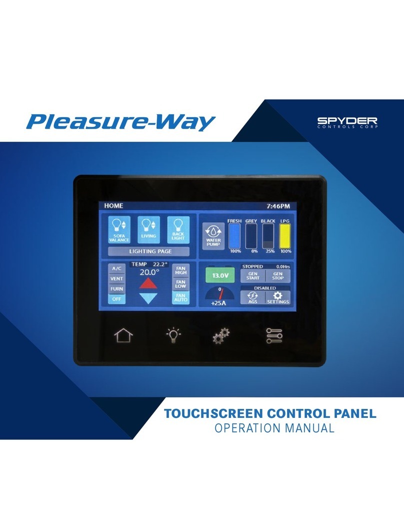
TOUCHSCREEN CONTROL PANEL
OPERATION MANUAL

2
G GETTING STARTED
12 VOLT BATTERY DISCONNECT SWITCH
To operate the touchscreen control panels, the 12 VOLT
BATTERY DISCONNECT switch must be in the ON position.
(This applies to the front and rear touchscreen control panels)
Touch anywhere on the touchscreen for the display to light up.
DISPLAY SCREEN MENU OPTIONS
The menu options are located off to the right of the
touchscreen control panel. There are five menu pages:
HOME, LIGHTING, POWER MANAGEMENT, MECHANICAL
AND SETTINGS.
Touch a menu icon to display the screen you want to access.
iGETTING STARTED
i12 Volt Battery Disconnect Switch
i Display Screen Menu Options
1HOME PAGE
1 Lighting Quick Access
2 Climate Control Center
3Water Pump
3Tank Level Panel
3 Water Heater
4DC Power
4 AC Power Display
4 Generator
5LIGHTING PAGE
5 Getting Started
6 Home Page Lighting Quick Access
7POWER MANAGEMENT PAGE
7 DC Power
8 AC Power
9 The EMS (Energy Management System)
9 Solar Charger
10 Solar Charger Settings
11 Generator
11 AGS Easy Setup
13 AGS Manual Setup
15 MECHANICAL PAGE
15 Power Sofa
16 Awning
16 Fan-Tastic Vent Fan
17 SETTINGS PAGE
18 Screen Settings
19 Diagnostics
TABLE OF
CONTENTS
HOME PAGE MECHANICAL PAGE
(Sofa, Awning, Fantastic Fan)
SETTINGS PAGE
(Module Status, G12 Status,
DCM3, Faults)
LIGHTING PAGE
POWER
MANAGEMENT PAGE

1
LIGHTING QUICK ACCESS
This area provides a short cut to your 3 most used lights.
(See LIGHTING PAGE 6) for customization.
The configuration shown here will allow you to turn
ON or OFF lighting for the KITCHEN, SOFA VALANCE,
READING and the BACK LIGHT.
Buttons with up/down arrows are capable of dimming.
Touch and hold the light button for brightening and
dimming of the lighting.
Select the LIGHTING PAGE button for a complete list of
lighting options.
HOME PAGE
To access the HOME page, select the icon from the menu off to the right of the touchscreen control panel.
Buttons will display in light blue when activated.
The HOME page will display the following: LIGHTING, CLIMATE CONTROL, WATER PUMP, WATER HEATER, TANK LEVELS, DC
POWER, GENERATOR START/STOP and AC SOURCE.

2
CLIMATE CONTROL CENTER
The CLIMATE CONTROL CENTER displays the inside
temperature and the desired temperature in the center circle.
The actual inside temperature of the coach is displayed
in the smaller number below the set temperature. The set
temperature is the large number selected by touching the
white dot and moving it around the temperature scale to the
desired temperature.
Use the MODE buttons on the left to select the desired item
that you want to operate. You can select: FURNACE, AIR
CONDITIONER, VENT FAN or FAN SPEED to the right. These
devices are thermostatically controlled.
NOTE: Fahrenheit or Celsius can be selected on the
Settings page.
FURNACE MODE (TRUMA VARIOHEAT)
If the desired temperature is above the interior temperature
the furnace will engage and warm the coach to the desired
temperature. At the desired temperature the furnace
will cycle off. If the temperature drops below the desired
temperature the furnace will cycle back on. Ensure that the
propane switch on the exterior of the coach is in the ON
position.
NOTE: Ensure that the fan speed on the right side is set to FAN
AUTO. If there is 110 volt available and the fan is left on HIGH or
LOW, the fan in the AC will engage during the furnace mode.
VENT MODE
If the desired temperature is below the interior temperature,
the roof vent fan will open and the fan will engage. The fan
will run at high speed until the interior temperature reaches
the desired temperature. When the interior temperature
reaches the desired temperature the fan will shut off,
however the vent lid will remain open. The fan will cycle off
and on to keep the desired temperature.
A/C MODE
120 volt power from a shore line or from the generator must
be present to activate the air conditioner. In the A/C mode
if the desired temperature is below the interior temperature
the roof top A/C will engage to cool the interior of the coach.
The FAN HIGH, FAN LOW and FAN AUTO are used to control
the air conditioner fan speed. If the FAN HIGH or FAN LOW is
chosen the air conditioner fan will continue to run while the
air conditioner compressor will cycle on and off.

3
If FAN AUTO is chosen the air conditioner fan will cycle
on and off a short time before, and a short time after the
air conditioner compressor engages, to keep the desired
temperature.
NOTE: The FAN HIGH, FAN LOW and FAN AUTO are used to
control the air conditioner fan speed only. These controls will
not affect the roof vent or the furnace fan speeds.
WATER PUMP
Select the WATER PUMP button to run the on-board water
pump.
Ensure there is water in the fresh water holding tank before
engaging the water pump. The water pump should not be
turned on when the motorhome is connected to city water.
It’s recommended that you turn off the water pump when
the water system is not in use or when you are going to be
away from your motorhome.
TANK LEVEL PANEL
The FRESH, GREY and BLACK tank levels. The fresh and grey
water tanks are located underneath the floor of the vehicle. The
black water tank is located above the floor directly under the
toilet.
The LPG indicates how full the LP tank is. The LP gauge is
located on the tank with a sending unit that sends levels to the
touchscreen control panels.
WATER HEATER
Please refer to the manufacturer’s operating instructions for
further information.
Select the WATER HEATER symbol to adjust.
Set water temperature using the - or + symbols. Press OK to
return to HOME PAGE.
The water heater setting will be displayed at the top right of the
HOME PAGE.

4
DC POWER (COACH BATTERIES)
This gauge displays the STATE-OF-CHARGE, BATTERY
VO LTAG E , BATTERY TEMPERATURE, and REAL TIME LOSS/
GAIN AMPERAGE.
(for more information see page 7)
AC POWER DISPLAY (120 VOLT POWER)
When operating your coach on AC power, the current power
source you are using will light up and be displayed on the
Home Page.
GENERATOR
This gauge displays the START/STOP SWITCH, GENERATOR
STATUS and AUTO GENERATOR START STATUS.
These buttons will start and stop your generator. Touch and
hold the button to start the generator. There will be a slight
delay before the starter engages.

5
To access the LIGHTING PAGE, select the icon from the menu off to the right side of the touchscreen control panel.
NOTE: LIGHTING PAGES will vary depending on the model.
GETTING STARTED
Select a light button to turn ON or OFF lighting associated with the area. Buttons will display in light blue when activated.
The LIGHT MASTER button turns ON or OFF all the lights inside the vehicle. The LIGHT MASTER button does not control AWNING
LIGHT or the PORCH LIGHT.
Buttons with a sliding bar are capable of dimming.
To turn OFF the screen display, select the BACK LIGHT button on the HOME page. To turn the screen display back ON, touch
anywhere on the screen.
WARNING: Ensure the awning light is off when the awning is retracted in the stow position.
LIGHTING PAGE

6
HOME PAGE LIGHTING QUICK ACCESS
The QUICK ACCESS LIGHTING buttons on the HOME page
can be customized to show any 3 lights, by following
these instructions:
1. Select the SETTINGS icon on the touchscreen control
panel.
2. Select the SCREEN SETTINGS button. This will bring up
the DEFAULT BUTTONS section.
3. Use the + and – buttons to adjust lighting options.
NOTE: BACK LIGHT is a required for the quick access panel
and cannot be changed.

7
POWER MANAGEMENT PAGE
The POWER MANAGEMENT PAGE will assist you in managing your power consumption. This
especially helpful when you are dry camping.
DC POWER
BATTERY PANEL
Indicates the state-of-charge of the batteries, battery voltage and the temperature of the
batteries. The temperature gauge measures the current temperature inside the coach battery
box and will help you determine if it’s safe to charge your batteries.
Battery voltage will vary depending on the load. The battery voltage will change depending on
the amount of charge the battery is receiving from the solar panel, engine alternator, or the
inverter/charger.
NOTE: The temperature of the batteries is important, do not charge the batteries if the
temperature is below 32 degrees Fahrenheit or 0 degrees Celsius.
To access the POWER MANAGEMENT PAGE, select the icon from the menu off to the right side of the touchscreen control panel.

8
LOSS/GAIN AMPERAGE METER
The LOSS/GAIN AMPERAGE METER gives a real time level of
DC amperage used in the motorhome. A positive number will
indicate that more amperage is going into the battery bank
than is being used. A negative number means the battery
bank is being drawn down.
ESTIMATION GAUGE
The ESTIMATION GAUGE gives an estimate of time remaining
for the DC power that can be drawn from the battery bank.
The average rating takes into consideration consumption over
a short period of time.
The ESTIMATION GAUGE also estimates the charging time
when plugged into shore power, on generator power, solar
charging or when the vehicle is running and the batteries are
being charged.
AC POWER
The AC POWER display will show the source of AC power
(GENERATOR, INVERTER or SHORE), the VO LTA G E of AC
power and the FREQUENCY of AC power. It will also indicate
the AMPERAGE draw of the 120 VAC appliances.

9
THE EMS (ENERGY MANAGEMENT SYSTEM)
The EMS monitors two of the heavy amperage draw appliances
(MICROWAVE/CONVECTION OVEN and the INDUCTION
COOK TOP) installed in the coach.
This ENERGY MANAGEMENT SYSTEM will limit the combined
amperage draw of these two appliances. If the amperage
SOLAR CHARGER
The SOLAR CHARGER module is connected to the Go Power
GP-RVC-30 MPPT Solar Controller.
From this screen you can turn ON or OFF the solar panel feed
into the solar controller by pressing the POWER symbol.
To the left shows the PANEL VOLTAGE before the controller,
the CHARGE VOLTAGE at the controller to the batteries and the
CHARGE AMPS the solar panels are producing.
Towards the middle of the display shows the type of charge that is coming from the panels. It will indicate if the controller is: OFF,
BULK, ABSORPTION and FLOAT for the various type of charge.
NOTE: Please refer to the MPPT solar controller manual for more information.
draw exceeds the parameters of the management system, the microwave GREEN display will turn to RED and the microwave will
be shut OFF. Once the amperage draw from the cook top drops below the threshold, the microwave will return to green and the
microwave can be reactivated.
The INDUCTION COOK TOP can draw up to 1800 watts or 15 amps. The MICROWAVE can draw up to 1600 watts or 13.3 amps.
The amount of WATTS/AMPS is determined by the settings of the appliances. In most cases the MICROWAVE and COOK TOP will
not be able to be used at the same time. There are other items in the coach that will also put a load on the electrical system.
MAXIMUM INPUT FROM POWER SOURCES:
Xantrex Inverter – 2000 watts or 16.6 amps
Onan Generator – Mercedes 2500 watts or 20.8 amps, Ford or Ram 2800 watts or 23.3 amps
Shore Power – 3600 watts or 30 amps

10
SOLAR CHARGER SETTINGS
Touch the GEAR symbol to display the settings page for the solar controller. This includes:
• Solar Charging Rate
• History of Charge
• Solar Charge Settings
• Solar Charge Controller Maximum Ratings

11
GENERATOR
The GENERATOR module will allow you to START and STOP the
generator, check the HOUR METER and set the parameters
and activate the AGS (AUTO GENERATOR START) system.
AUTOMATIC GENERATOR START (AGS)
This feature can be used to charge the coach batteries and/
or for climate control in your coach.
To operate the AGS system the vehicle must be turned OFF,
the 12V battery disconnect switch must be ON, and the fuel
must be on or at the appropriate level.
For the ASCENT and PLATEAU models, the LP switch must be
in the ON position and the LP tank must have adequate fuel.
For the LEXOR and ONTOUR models, there must be at least
¼tank of gasoline.
Select the AGS button to enable the AUTOMATIC
GENERATOR START function. A display will appear with a
warning and instructions. Touch and hold CONTINUE for 5
seconds to activate the AGS system. Once the system is
activated it will return to the main POWER MANAGEMENT
PAGE and the AGS will be in blue.
NOTE: It is recommended that you manually start the
generator allowing it to run a short period of time before
setting the AGS system. This will ensure adequate fuel
and operation of the generator before relying on the AGS
system to start the generator and power the appliances.
WARNING: Do not use the AUTOMATIC GENERATOR
START if you are plugged into shore power, or if you are in
an area where running the generator is prohibited.
WARNING: Ensure all windows and doors are closed
on the vehicle while operating your generator. This will
eliminate generator exhaust from entering your coach.

12
To activate the AGS function, first choose the set up by
touching the GEAR symbol. The GEAR symbol will bring up a
screen that allows you to choose between EASY SET UP or
MANUAL SET UP.
AGS EASY SETUP
Select EASY SETUP for a quick set up of the START
parameters.
By touching EASY SETUP it will allow you to choose
which items will trigger the AGS system. You can choose
BATTERY CHARGING or CLIMATE CONTROL. To ACTIVATE or
DEACTIVATE the systems touch the box next to the system
you want to activate the AGS. A CHECK MARK symbol will
appear when the system is active.
STARTING THE GENERATOR
The first page displayed will ask when you want the generator
to AUTO START. Select the boxes to check or uncheck the
reason to enable.
Select the NEXT button to continue.
STARTING CONDITIONS FOR LOW BATTERY
This page will enable you to set the PERCENTAGE OF
BATTERY CHARGE when the AGS system is activated. The
generator when running will charge the coach batteries
through the inverter/charger.
Use the + and – buttons to adjust the settings.
Select the NEXT button to continue.
STOPPING CONDITIONS FOR LOW BATTERY
This page will enable you to set the PERCENTAGE OF
BATTERY CHARGE at which point the generator will turn OFF.
Use the + and – buttons to adjust the settings.
Select the NEXT button to continue.

13
GENERATOR RUN LIMITS
This page will enable you to set the parameters for RUN TIME
for the air conditioner settings. Once the air conditioner
has brought the coach down to the chosen temperature
and cycled off, the generator should continue to run for ten
minutes.
It will also allow you to set the MAXIMUM run time for the
generator.
Use the + and – buttons to adjust the settings.
Select the NEXT button to continue.
QUIET TIME SETTINGS
Select the box in the top right hand corner to enable or
disable QUIET TIME settings. QUIET TIME settings allow you
to determine when the generator will not be allowed to run.
Select the box above the FINISH button to enable or disable
a battery top up just before the system goes into QUIET TIME
settings.
Select the FINISH button to complete EASY SETUP.
AGS MANUAL SETUP
Select MANUAL SETUP for more in depth set up choice and
will allow you to set all parameters for the the AGS system.
You can choose BATTERY or HVAC system to trigger the AGS.
You can choose your RUN TIMES, QUIET TIMES and BATTERY
CAPACITY for shut down parameters.
Touch FINISH when complete to return to the POWER
MANAGEMENT main page. Touch AGS to enable the AGS
system. Hold continue for 5 seconds to trigger the AGS
system.
NOTE: If both the LOW BATTERY VOLTAGE and the HVAC
LOADS are activated, which ever one needs the most run
time to acquire the desired result will override the other
setting.
NOTE: When AGS is used for the HVAC system (air
conditioning), the appliance must be selected on the HOME
page, the temperature must be selected and set on the
HOME page, and the fan on the HOME page should be set
to FAN AUTO.

14
START TRIGGERS
Select LOW BATTERY VOLTAGE or HVAC LOADS to turn on the
required triggers for AUTO GEN START. Buttons will display in
light blue when activated.
Use the + and – buttons to adjust the settings for:
• GENERATOR START PERCENTAGE
• NUMBER OF RESTART TRIES
RUNNING
Use the + and – buttons to adjust the settings for the
GENERATOR RUN TIME. This applies the HVAC setting.
STOPPING
Use the + and – buttons to adjust the settings for the
PERCENTAGE OF BATTERY CHARGE before the generator will
shut OFF. This applies to the LOW BATTERY VOLTAGE setting.
QUIET TIME
Select QUIET TIME button to set the parameters for the
QUIET TIME settings.
Use the + and – buttons to adjust the settings.

15
To access the MECHANICAL PAGE, select the icon from the menu off to the right side of the touchscreen control panel.
These include: THE FAN-TASTIC VENT FAN, AWNING AND POWER SOFA.
POWER SOFA
The sofa EXTEND and RETRACT module will allow you to lay
your sofa flat or bring it to a upright position. When touched
the touch pads will light up in blue. If there is a fault, the
touch pad will turn red. If the touch pad turns red, check to
see if there is anything caught under or between the sofa
cushions. Once the obstruction is clear touch the pad again
and the sofa will continue to EXTEND or RETRACT.
Touch and hold the EXTEND button until the sofa is fully
extended. Touch and hold the RETRACT button until the sofa
is completely retracted.
WARNING: Do not sit on sofa when operating the power sofa
functions.
MECHANICAL PAGE

16
AWNING (ENTRY DOOR PANEL ONLY)
Ensure the rear passenger side door and sliding door are
CLOSED before operating the awning.
Touch and hold the EXTEND button until the awning is fully
extended. Touch and hold the RETRACT button until the
awning is completely retracted.
The awning can be operated when the IGNITION OFF light is
lit in green. The awning will not operate when the vehicle is
running.
WARNING: Always ensure the awning is in the fully
retracted position before moving or driving the coach. The
awning does not automatically retract when the vehicle is
started.
FAN-TASTIC VENT FAN
Select LID UP or LID DOWN button to open or close the vent.
Select the FAN button to start the Fan-Tastic Vent fan.
(This fan is an exhaust fan used to draw air out of the coach).
The fan is also controlled by the thermostat. Ensure the
temperature of the thermostat is higher than the inside
temperature.
Use the + and – buttons to adjust the speed of the fan.
NOTE: The fan is equipped with a rain sensor so the fan
cannot be operated when it is raining. The fan cannot be
operated when the fan lid is closed.

17
TEMPERATURE UNITS
Select this button to change from FAHRENHEIT to CELSIUS.
This will allow you to monitor the interior temperature and set
the thermostat according to your chosen measure.
SCREEN BRIGHTNESS
Slide the bar to set the screen to the desired lumens.
SETTING THE CLOCK
Select the left side UP/DOWN arrows to change the hour
reading on the display. Select the right side UP/DOWN
arrows to change the minutes.
To change from AM to PM you must run the clock through the
12 hour cycle. You can also adjust for a 12hr or a 24hr clock.
NOTE: Setting the clock is critical to the Automatic
Generator Start Feature.
To access the SETTINGS PAGE, select the icon from the menu off to the right side of the touchscreen control panel.
This page will allow you to adjust TEMPERATURE UNITS, TIME, DISPLAY ITEMS, MODEL and DIAGNOSTICS.
SETTINGS PAGE

18
SCREEN SETTINGS
Select the SCREEN SETTINGS button to bring up the POWER
SAVING MODE, COLOR SCHEME, the DEFAULT PAGE and the
DEFAULT BUTTONS (quick access lighting on HOME page).
POWER SAVINGS
By using the + or – buttons, you can set the number of
MINUTES the screen will be active before it goes off. Once
the screen turns OFF, touch anywhere on the screen to turn
back ON.
COLOR SCHEME
This page will allow you to select a LIGHT on dark or a DARK
on light color scheme for the display screen.
DEFAULT PAGE
Selecting the ENABLE button on the DEFAULT PAGE will
allow you to set the time that the screen display will stay
active on any particular page. When enabled by use of the +
or – buttons, you can set the SCREEN DISPLAY duration, and
choose a page as the DEFAULT PAGE.
For example if you choose the HOME page as your default
page and you are on the LIGHTING page, the screen will
return to the HOME page after the set duration.
The DEFAULT BUTTONS section allows you to customize the
QUICK ACCESS LIGHTING on the HOME page. (See page 6)
Other manuals for Pleasure-Way
1
Table of contents
Other Spyder Touchscreen manuals
Popular Touchscreen manuals by other brands

Elo TouchSystems
Elo TouchSystems 2799L user manual

Johnson Controls
Johnson Controls Tyco HS2TCHP E user manual

InFocus
InFocus INF5532AG Handling guide

SunBriteDS
SunBriteDS DS-3214TSL Operator's manual

DTEN
DTEN D7X Android Edition Product guide

Elo TouchSystems
Elo TouchSystems 1725C Series Specification sheet

Legamaster
Legamaster PROFESSIONAL e-Screen 55 inch ETD Quick setup guide

Savant
Savant ITP-E5500V2 Series Quick reference guide

Advantech
Advantech TPC-660G user manual

CRE
CRE GENSYS COMPACT PRIME quick start

Cincoze
Cincoze CV-108 user manual

Elo TouchSystems
Elo TouchSystems ETXX87C-4SWA-1 Series user guide