Spyder Pleasure-Way User manual

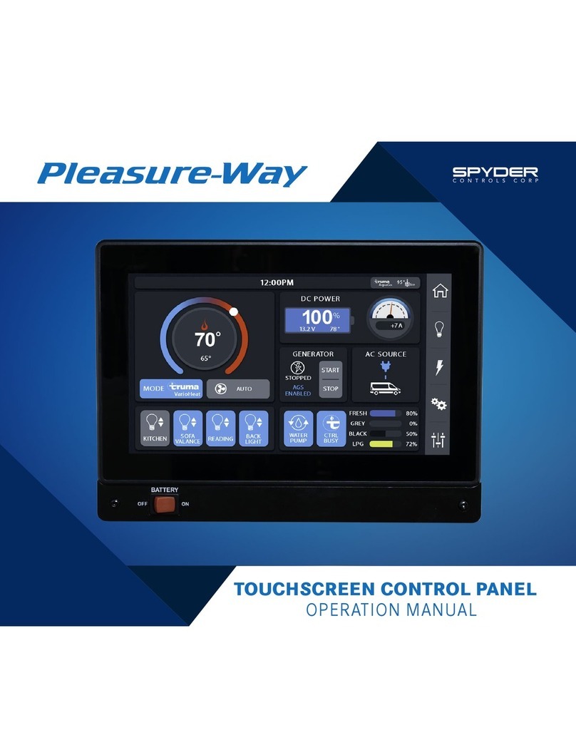
TOUCHSCREEN CONTROL PANEL
OPERATION MANUAL


3

4
1GETTING STARTED
1 12 Volt Battery Disconnect Switch
1 Menu Options
1HOME PAGE
1 Lighting Quick Access
2 Water Pump
2 Tank Level Panel
2 Climate Control Center
4 Battery Voltage
4 Loss/Gain Amperage Meter
4 Generator Start/Stop
5 Automatic Generator Start
6 AGS Easy Setup
7 AGS Manual Setup
9LIGHTING PAGE
10 Getting Started
10 Home Page Lighting Quick Access
11 MECHANICAL PAGE
11 Getting Started
11 Fan-Tastic Vent®Fan
11 Awning
12 Power Sofa
12 SETTINGS PAGE
12 Getting Started
13 Screen Settings
14 Diagnostics
TABLE OF
CONTENTS

1
G GETTING STARTED
12 VOLT BATTERY DISCONNECT SWITCH
To operate the touchscreen control panels, the 12 volt battery
disconnect switch must be in the ON position.
(This applies to the front and rear touchscreen control panels)
MENU OPTIONS
The menu options are located at the bottom of the
touchscreen control panel. There are four menu options:
HOME, LIGHTS, MECHANICAL AND SETTINGS.
Select a menu icon to access the appropriate page.
To access the HOME page, select the icon from the menu at
the bottom of the touchscreen control panel.
Buttons will display in light blue when activated.
The HOME page will display the following:
LIGHTING, CLIMATE CONTROL, WATER PUMP, TANK LEVELS,
BATTERY VOLTAGE, LOSS/GAIN AMPERAGE,
GENERATOR START/STOP, and AUTOMATIC GENERATOR
START/SETTINGS.
LIGHTING QUICK ACCESS
This area provides a short cut to your 3 most used lights.
(See LIGHTING PAGE 10) for customization.
The configuration shown here will allow you to turn on or off
lighting for the SOFA VALANCE, LIVING (main living room) and
the BACK LIGHT.
Buttons with up/down arrows are capable of dimming.
Touch and hold the light button for brightening and dimming of
the lighting.
Select the LIGHTING PAGE button for a complete list of
lighting options.
HOME PAGE

2
WATER PUMP
Select the WATER PUMP button to run the on-board water
pump.
Ensure there is water in the fresh water holding tank before
engaging the water pump. The water pump should not be
turned on when the motorhome is connected to city water.
It’s recommended that you turn off the water pump when
the water system is not in use or when you are going to be
away from your motorhome.
TANK LEVEL PANEL
The FRESH, GREY and BLACK tank levels measure in 25%
increments.
The propane tank (LPG) levels will read in a single percentage.
CLIMATE CONTROL CENTER
The CLIMATE CONTROL CENTER displays the inside
temperature and the desired temperature in the center column.
The actual inside temperature of the coach is displayed in black
above the desired temperature. The desired temperature can
be set with the use of the red and blue arrows. The blue arrow
will allow you to lower the desired temperature. The red arrow
will raise the desired temperature.
Use the MODE buttons on the left to select the desired item
that you want to operate. You can select:
FURNACE, VENT or AIR CONDITIONER.
These devices are thermostatically controlled.
NOTE: MODE buttons display in light blue when activated.

3
In the furnace mode (FURN)
If the desired temperature is above the interior temperature
the furnace will engage and warm the coach to the desired
temperature. At the desired temperature the furnace
will cycle off. If the temperature drops below the desired
temperature the furnace will cycle back on. Ensure that the
propane switch on the exterior of the coach is in the ON
position.
NOTE: Ensure that the fan speed on the right side of the
red and blue arrow is set to FAN AUTO. If there is 110 volt
available and the fan is left on high or low, the fan in the AC
will engage during the furnace mode.
In the VENT mode
If the desired temperature is below the interior temperature,
the roof vent fan will open and the fan will engage. The fan will
run at high speed until the interior temperature reaches the
desire temperature. When the interior temperature reaches
the desired temperature the fan will shut off, however the vent
lid will remain open. The fan will cycle off and on to keep the
desired temperature.
In the A/C mode
110 volt power from a shore line or from the generator must
be present to activate the air conditioner. In the A/C mode
if the desired temperature is below the interior temperature
the roof top A/C will engage to cool the interior of the coach.
The FAN HIGH, FAN LOW and FAN AUTO are used to control
the air conditioner fan speed. If the FAN HIGH or FAN LOW is
chosen the air conditioner fan will continue to run while the air
conditioner compressor will cycle on and off.
If FAN AUTO is chosen the air conditioner fan will cycle
on and off a short time before, and a short time after the
air conditioner compressor engages, to keep the desired
temperature.
NOTE: The FAN HIGH, FAN LOW and FAN AUTO are used to
control the air conditioner fan speed only. These controls
will not affect the roof vent or the furnace fan speeds.

4
BATTE RY VOLTAGE
This gauge displays the battery voltage. The battery voltage
will vary depending on the load. The battery voltage will
change depending on the amount of charge the battery is
receiving from the solar panel, engine alternator, or the
inverter/charger.
GENERATOR START/STOP
These buttons will start and stop your generator. Touch and
hold the button to start the generator. There will be a slight
delay before the starter engages.
You also can monitor the number of hours that the generator
has operated. This is important for service.
LOSS/GAIN AMPERAGE METER
The loss/gain amperage meter will allow you to monitor the
amount of draw on the coach batteries. This allows the user
to balance out power use and will enhance the dry camping
experience. The amperage readings will vary depending on the
number of appliances in use, and the amount of charge going
into the coach.

5
AUTOMATIC GENERATOR START
The automatic generator start (AGS) can be used to charge the
coach batteries and/or for climate control in your coach.
To enable AGS for the Ascent, Plateau, and Plateau XL
models, the LP switch must be in the ON position and the LP
tank must have adequate fuel. To enable AGS on the Lexor
models there must be at least ¼ tank of gasoline.
Select the AGS button to enable the automatic generator
start function. A display will appear with a warning and
instructions. AGS will not engage if you do not cycle the
ignition to the run position within the allotted time or if you
touch CANCEL on the screen.
NOTE: The ignition should only remain in the run position
for less than 10 seconds otherwise AGS will be disabled.
Select the SETTINGS button to set the parameters for
Auto Generator Start.
After selecting the SETTINGS button you will have a choice
between EASY SETUP or MANUAL SETUP.
WARNING:Do not use the automatic generator start if
you are plugged into shore power, or if you are in an area
where running the generator is prohibited.

6
GENERATOR RUN LIMITS
This page will enable you to set the parameters for run time
for the air conditioner settings. Once the air conditioner has
brought the coach down to the chosen temperature and cycled
off, the generator should continue to run for ten minutes.
It will also allow you to set the maximum run time for the
generator.
Use the + and – buttons to adjust the settings.
Select the NEXT button to continue.
AGS EASY SETUP
Select EASY SETUP for a quick set up of the start parameters.
STARTING THE GENERATOR
The first page displayed will ask when you want the generator
to auto start. Select the boxes to check or uncheck the reason
to enable.
Select the NEXT button to continue.
STARTING CONDITIONS FOR LOW BATTERY
This page will enable you to set the voltage and the period
of time below that voltage, where you want your generator
to start. The generator when running will charge the coach
batteries through the inverter/charger.
Use the + and – buttons to adjust the settings.
Select the NEXT button to continue.

7
STOPPING CONDITIONS FOR LOW BATTERY
This page will enable you to set the parameters for the battery
charging system. You will be able to set the desired charge
voltage as well as the amount of time that the battery has held
the voltage before the generator will shut down.
Use the + and – buttons to adjust the settings.
Select the NEXT button to continue.
QUIET TIME SETTINGS
Select the box in the top right hand corner to enable or disable
quiet time settings. Quiet time settings allow you to determine
when the generator will not be allowed to run.
Select the box above the FINISH button to enable or disable
a battery top up just before the system goes into quiet time
settings.
Select the FINISH button to complete EASY SETUP.
AGS MANUAL SETUP
Select MANUAL SETUP for more in depth set up choice.
START TRIGGERS
Select LOW BATTERY VOLTAGE or HVAC loads to turn on the
required triggers for AUTO GEN START. Buttons will display in
light blue when activated.
Select QUIET TIME button to set the parameters for the quite
time settings.
Use the + and – buttons to adjust the settings.

8
STARTING
Use the + and – buttons to adjust the settings for:
• battery voltage
• delay if the generator fails to start
• number of restart tries
RUNNING
Use the + and – buttons to adjust the settings for the generator
run time. This applies the HVAC setting.
STOPPING
Use the + and – buttons to adjust the settings for the voltage
parameters and the amount of time the battery remains at that
voltage before the generator will shut off. This applies to the
low battery voltage setting.
NOTE: If both the LOW BATTERY VOLTAGE and the HVAC
LOADS are activated, which ever one needs the most run
time to acquire the desired result will override the other
setting.
NOTE: When automatic generator start is used for the
HVAC system (air conditioning or heating), the appliance
must be selected on the main screen, the temperature
must be selected and set on the main screen and the fan
on the main screen should be set to FAN AUTO.

9
LIGHTING PAGE
To access the LIGHTING PAGE, select the icon from the menu
at the bottom of the touchscreen control panel, or select the
LIGHTING PAGE button located underneath quick access
lighting options on the HOME page.
NOTE: LIGHTING PAGES will vary depending on the model.
ASCENT TS & LEXOR TS/FL
PLATEAU TS/FL
PLATEAU XLMB/XLTD/XLTS

10
GETTING STARTED
Select a light button to turn ON or OFF lighting associated with
the area. Buttons will display in light blue when activated.
The LIGHT MASTER button turns ON or OFF all the lights
inside the vehicle. The LIGHT MASTER button does not control
AWNING LIGHT or the PORCH LIGHT.
Buttons with up/down arrows are capable of dimming.
Touch and hold the light button for brightening and dimming of
the lighting.
To turn OFF the screen display, select the BACK LIGHT button
on the HOME page. To turn the screen display back ON, touch
anywhere on the screen.
WARNING: Ensure the awning light is off when the awning
is retracted in the stow position.
HOME PAGE LIGHTING QUICK ACCESS
The quick access lighting buttons on the HOME page
can be customized to show any 3 lights, by following
these instructions:
NOTE: It is recommended that you keep the BACK LIGHT or
PANEL LIGHTS as one of the three options as this will allow
you to turn ON or OFF the touchscreen display.
1. Select the SETTINGS icon from the menu at the bottom
of the touchscreen control panel.
2. Select the SCREEN SETTINGS button. This will bring up
the DEFAULT BUTTONS section.
3. Use the + and – buttons to adjust lighting options.
NOTE: PANEL LIGHTS and BACK LIGHT are the same
function.

11
MECHANICAL PAGE
GETTING STARTED
To access the MECHANICAL page, select the icon from the
menu at the bottom of the touchscreen control panel.
These include:
THE FAN-TASTIC VENT®FAN, AWNING AND POWER SOFA.
FAN-TASTIC VENT®FAN
Select LID UP or LID DOWN button to open or close the vent.
Select the FAN button to start the Fan-Tastic Vent®fan.
(This fan is an exhaust fan used to draw air out of the coach).
The fan is also controlled by the thermostat. Ensure the
temperature of the thermostat is higher than the inside
temperature.
Use the + and – buttons to adjust the speed of the fan.
NOTE: The fan is equipped with a rain sensor so the fan
cannot be operated when it is raining. The fan cannot be
operated when the fan lid is closed.
AWNING
Touch and hold the EXTEND button until the awning is fully
extended. Touch and hold the RETRACT button until the awning
is completely retracted.
The awning can be operated when the IGNITION OFF light
is lit in green. The awning will not operate when the vehicle
is running.
WARNING: Ensure the awning is fully retracted before
starting the vehicle engine. The awning does not
automatically retract when the vehicle is started.

12
POWER SOFA
Touch and hold the EXTEND button until the sofa is fully
extended.
Touch and hold the RETRACT button until the sofa is
completely retracted.
The power sofa will not move unless the buttons are held.
WARNING: Do not sit on sofa when operating the power
sofa functions.
SETTINGS PAGE
GETTING STARTED
To access the SETTINGS page, select the icon from the menu
at the bottom of the touchscreen control panel. This screen
will allow you to adjust TEMPERATURE UNITS, TIME, DISPLAY
ITEMS, MODEL and DIAGNOSTICS.
TEMPERATURE UNITS
Select this button to change from Fahrenheit to Celsius. This
will allow you to monitor the interior temperature and set the
thermostat according to your chosen measure.
SCREEN BRIGHTNESS
Use the + or - buttons to set the screen to the desired lumens.
SETTING THE CLOCK
Select the left side up/down arrows to change the hour
reading on the display. Select the right side up/down arrows to
change the minutes.
To change from AM to PM you must run the clock through the
12 hour cycle.
NOTE: Setting the clock is critical to the Automatic
Generator Start Feature.

13
SCREEN SETTINGS
Select the SCREEN SETTINGS button to bring up the POWER
SAVING MODE, the DEFAULT PAGE and the DEFAULT
BUTTONS (quick access lighting on HOME page).
Select the ENABLE button to activate the POWER SAVING
mode. By using the + or – buttons, you can set the number of
minutes the screen will be active before it goes off. Once the
screen turns off, touch anywhere on the screen to turn back
on.
Selecting the ENABLE button on the DEFAULT PAGE will allow
you to set the time that the screen display will stay active
on any particular page. When enabled by use of the + or –
buttons, you can set the screen display duration, and choose a
page as the default page.
*For example if you choose the HOME page as your default page
and you are on the LIGHTING page, the screen will return to the
HOME page after the set duration.
The DEFAULT BUTTONS section allows you to customize the
quick access lighting on the HOME page. (See page 10)

14
DIAGNOSTICS
Select the DIAGNOSTICS button to trouble shoot the DC
ELECTRICAL SYSTEM.
Select the STATUS button for status of each system.
If the STATUS button is green the item is functioning as normal
and the item is active.
If the STATUS button is grey this item is not in use at this time.
If the STATUS button is red there is a fault with this item (this
will be highlighted in the FAU LTS page).
Select the G6HOUSE to display all circuits in the vehicle.
If the circuit is lit in green it is active and being used.
If the circuit is lit in grey the circuit is not being used and the
items on that circuit are not turned on.
If the circuit is lit in red there is a fault in that circuit.
Select the FAULTS button to view all faults in the system.

15
PLEASE NOTE:
Appliances and options may change without notice and
some appliances and equipment may be optional. Due
to Pleasure-Way’s policy of continuous improvement,
Pleasure-Way Industries Ltd. reserves the right to make
product changes at any time without incurring obligation.
If you require further information about the touchscreen
control panels, please contact one of the following:
1. Your Pleasure-Way Dealer.
2. Pleasure-Way Industries Ltd., at 1-800-364-0189
3. Spyder Controls Ltd. 1- 866-919-9092

16
TOUCHSCREEN CONTROL PANEL OPERATION MANUAL
302 PORTAGE AVENUE
SASKATOON SK, CANADA S7J 4C6
TEL: 800.364.0189 FAX: 306.934.7085
WWW.PLEASUREWAY.COM
Version 3.0
Other manuals for Pleasure-Way
1
Table of contents
Other Spyder Touchscreen manuals
Popular Touchscreen manuals by other brands

Elo TouchSystems
Elo TouchSystems 2242L user guide

Speechi
Speechi ST-XX-UHD-AND-HP-007-S-QSG quick start guide

Bridgetek
Bridgetek LDSBus BRT AN 080 user guide

Elo TouchSystems
Elo TouchSystems 3200L user manual

Carrier
Carrier equipment touch Installation and setup guide

Critical Environment Technologies
Critical Environment Technologies Visio-3 General operation guide