Fireye NXD410TS Owner's manual

© 2020 Carrier 1
NXD-4102
July 24, 2020
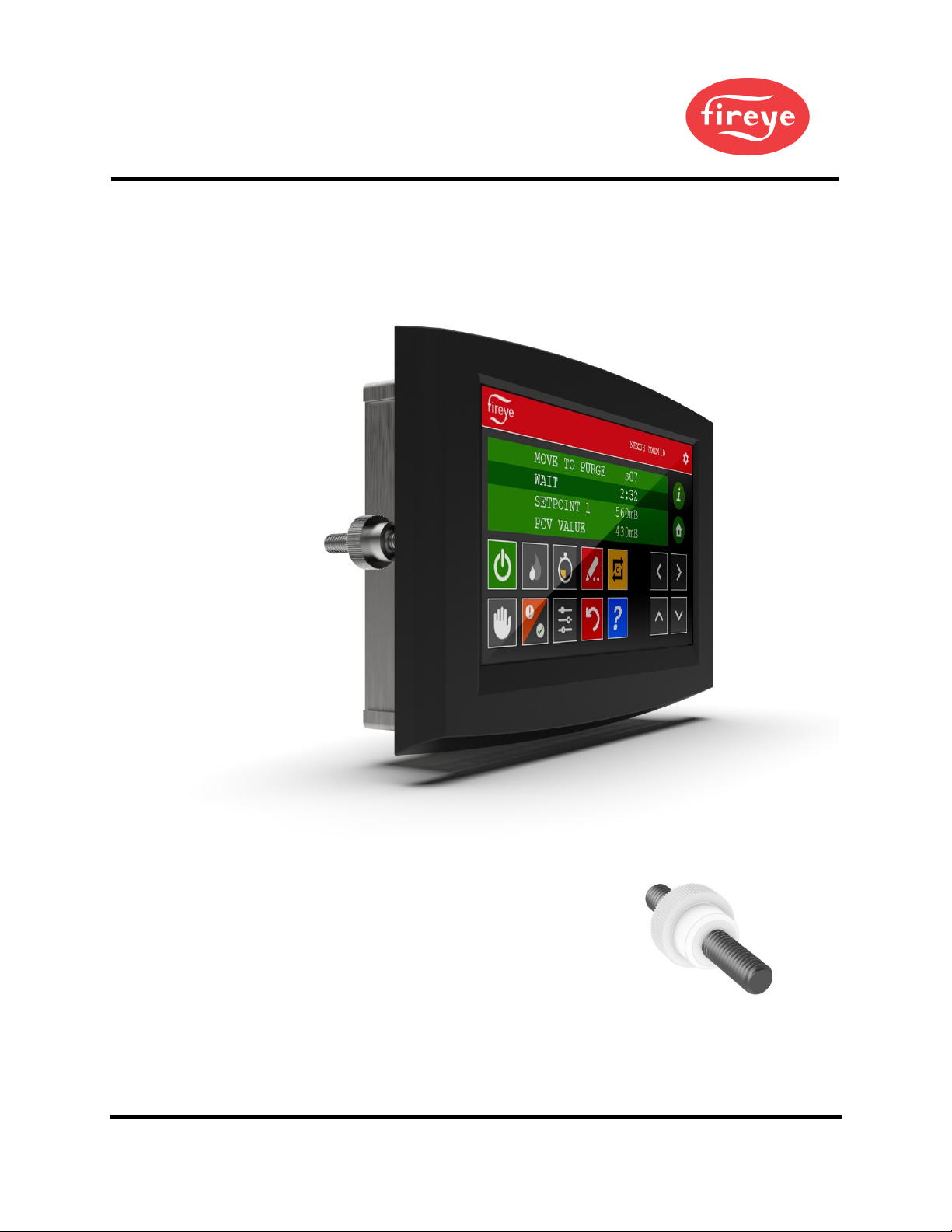
NXD410TS
Touchscreen Interface
Installation and Operation
DESCRIPTION
The NXD410TS provides the means to setup, monitor and display information from the NXF4000 and
PPC4000 series of controls as well as any connected accessories. It provides a full touchscreen
interface for monitoring, configuration and commissioning. The NXD410TS touchscreen is panel
mounted and connects to the NXF4000 or PPC4000 control using a serial communication cable.
NOTE: This bulletin is intended to be a supplement to bulletins NXF-4001 and PPC-4001, which
covers the installation and operation of the NXF4000 and PPC4000 controls, respectively. Please
refer to those bulletins for any specific information on installation, features, commissioning or
operation of the connected controls.
`
WARNING: Failure to properly install, operate, or commission the equipment
in this manual could result in significant property damage, severe injury, or
death. It is the responsibility of the owner or user to ensure that the
equipment described is installed, operated and commissioned in compliance
with this manual and other system component manuals, as well with all
applicable national and local codes.
WARNING: Boiler operation, maintenance, and troubleshooting shall only be
conducted by trained personnel. Persons troubleshooting lockouts or
resetting the control must respond properly to troubleshooting error codes as
described in this product bulletin. Jumpers being used to perform static test
on the system must only be used in a controlled manner and must be removed
prior to the operation of the control. Such tests may verify the external
controllers, limits, interlocks, actuators, valves, transformers, motors and
other devices are operating properly. Such tests must be conducted with
manual fuel valves in the closed position only. Replace all limits and interlocks
not operating properly, and do not bypass limits in interlocks. Failure
to follow
these guidelines may result in an unsafe condition hazardous to life and
property.

2 © 2020 Carrier
TABLE OF CONTENTS
DESCRIPTION .............................................................................................................................................................1
TECHNICAL DATA NXD410TS ................................................................................................................................3
ORDERING INFORMATION......................................................................................................................................4
MOUNTING NXD410TS .............................................................................................................................................5
Method ......................................................................................................................................................................5
Cutout........................................................................................................................................................................6
Template....................................................................................................................................................................6
WIRING ........................................................................................................................................................................7
Terminals...................................................................................................................................................................7
Wiring .......................................................................................................................................................................8
OPERATION ................................................................................................................................................................9
Quick Keys..............................................................................................................................................................10
CERTIFICATIONS NXD410TS.................................................................................................................................12
NOTICE ......................................................................................................................................................................13
WARRANTIES...........................................................................................................................................................13

© 2020 Carrier 3
TECHNICAL DATA NXD410TS
Screen type: Projected capacitive
Resolution: 480 x 272
Diagonal screen area: 109.2mm (4.3 in.)
Interface method: Terminal mode via RS-422
Nominal voltage 24 VDC ± 20%
Nominal power consumption: 0.21A @ 24VDC (5W)
Operating temperature range: 0°C to +50°C (32°F to +122°F)
Storage temperature range: -30°C to +80°C (-22°F to +176°F)
Humidity: 5% to 85%, non-condensing
Degree of protection: Indoor use only, IP40
Installation orientation: Landscape (horizontal)
Unit dimensions faceplate: 128mm x 87mm (5.03 in. x 3.43 in.)
Unit dimensions depth: 32mm (1.26 in.)
Panel cutout dimensions: See mounting section for diagram
Weight: 0.34 kg. (0.75 lb.)
4 © 2020 Carrier
ORDERING INFORMATION
Touchscreen Interfaces
NXD410TS Touchscreen interface, 4.3 inch diagonal screen size, 24VDC, for use with
NXF4000 or PPC4000 parallel positioning system
Accessories
59-561 Cable to connect NXD410TS to NXF4000 or PPC4000, separate power and
communication, sold by the foot.
`
WARNING: Use of third party power supply is permitted, provided the power supply
meets NEC CLASS 2 to protect against fire and electrical shock.
© 2020 Carrier 5
MOUNTING NXD410TS
Method
The NXD410TS requires a non-symmetrical cutout and is secured using two knurled-head thumb nuts.
Refer to the figure below for the layout of these thumb nuts.
View of NXD410TS showing placement of the knurled-head thumb nuts (one on each side)
The thumb nuts attach to threaded posts which are threaded into
inserts on each side of the screen. See the figure to the right for a
diagram of the thumb nut attached to the post. The post and
thumb nuts use M4x0.7 thread and the posts are 25mm long. If a
post and thumb nut are lost and need replacement, an M4x0.7
screw that is 10mm long can be used in combination with a
washer.
Post with knurled-head thumb nut

6 © 2020 Carrier
Cutout
Use the following dimensions to mark the necessary cutout and holes to mount the screen. The orientation
of the diagram is from the face of the panel where the cutout is being made. A template is also provided
below that may be printed at 100% scale and used to provide a guide.
Template

© 2020 Carrier 7
WIRING
Terminals
The recommended cable (59-561) contains six wires: two power wires (18AWG) and four communication
wires (22AWG) in two twisted pairs. There is also a drain wire.
The figures below show the connectors for both power and communications.
Power
Communications
The connector labeled 24V supplies the 24VDC power to the
unit. The connection is polarity sensitive and is designated on the
legend. It is recommended to use wire between 16AWG and
18AWG for this connection. The connector is a two-position
5.08mm pluggable terminal block with screw terminals.
The connector labeled “10101” (symbol/icon for serial port) is
the RS-422 serial port used for the terminal communication to the
NXF4000 or PPC4000. The connections are polarity sensitive
and are designated on the legend. There are connections required
for both send and receive – if one is correct and the other is not,
operation may be erratic. It is recommended to use a single cable
with two twisted wire pairs between 18AWG and 22AWG for
this connection. The connector is a four-position 5.08mm
pluggable terminal block with screw terminals.
The connections to the NXF4000 or PPC4000 are to the
connectors P2 for power and P12 for communications. Refer to
bulletin NXF-4001 or PPC-4001 for further clarification on
terminal ratings, power supply considerations and any other
issues that may not be covered in this bulletin. Refer to the table
below for the required wiring connections between the connected control and the screen.
NXF4000/PPC4000 terminal blocks

8 © 2020 Carrier
Wiring
If the NXD410TS is being used to replace the NXD410, the existing 59-562-2 cable can be used simply by
removing and discarding the DSUB connector on the terminal end. The cable itself is identical and may be
reused.
The wiring between the devices is shown in the table below:
59-561 wire color
Wire gauge
NXF4000/PPC4000 terminal
NXD410TS terminal
Red
18AWG
P2-1
24V(+)
Black
18AWG
P2-4
24V(-)
Yellow
22AWG
P12-7
10101(Rx+)
Blue
22AWG
P12-8
10101(Rx-)
Brown
22AWG
P12-9
10101(Tx-)
Orange
22AWG
P12-10
10101(Tx+)
In the event of electrical noise in the cabling, the drain wire inside the 59-561 cable can be connected to
earth ground on one end of the cable. Normally this is not required as the twisted pairs used for the
communication wiring handles the noise rejection.
© 2020 Carrier 9
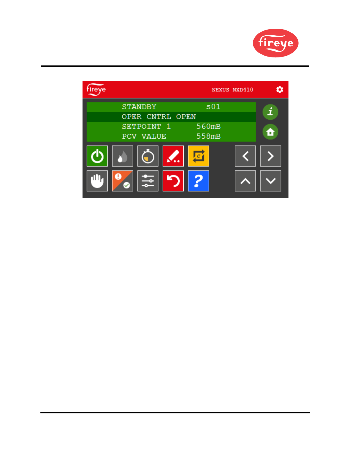
OPERATION
The touchscreen display provides four lines of information. The active area of the display is highlighted on
the second line. The four directional keys (located on the right-hand corner) are used to navigate through
the menus and to update values. The next section shows the various symbols and their functions.
The NXD410TS contains a number of Quick Keys that allow the user to access that function directly. For
these Quick Keys to operate, the installer or operator must first access the KEYPAD SETUP menu where
the user defines if a Quick Key is used or unused. Quick Keys are non-volatile meaning the state of the
function is retained in memory should a power recycle occur. See Fireye bulletin NXF-4001 or PPC-4001
for additional information on NXF4000 or PPC4000 configuration and functionality.
10 © 2020 Carrier
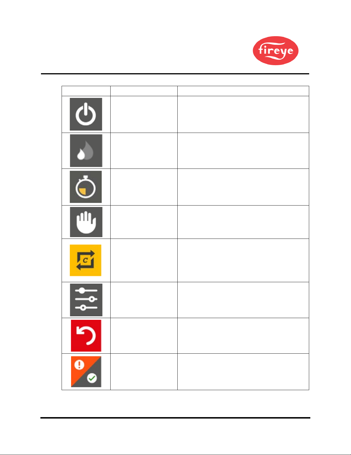
Quick Keys
Button
Key Name
Description
BURNER ON
Used to turn the burner on or off. The button changes
from gray to green when the burner is in the ON
mode. This button can be enabled via the KEYPAD
SETUP menu. Note that this button does not override
any recycle limits.
LOW FIRE
Used to force the burner into low fire operation. The
button changes from gray to green when active. This
button can be enabled via the KEYPAD SETUP
menu.
LEAD LAG
Used to make the control the master when sequencing
is enabled. The button changes from gray to green
when active. This button can be enabled via the
KEYPAD SETUP menu. SEQUENCING SETUP
MASTER SLCT must also be set to KEYPAD.
AUTO MAN
Used to force the burner into manual firing rate
operation. The button changes from gray to green
when active. This button can be enabled via the
KEYPAD SETUP menu.
C-MODE
Used to go to the Commissioning or Adjust Ratio
mode. The mode entered depends upon the passcode
used and whether the burner is firing at the time.
While in Commissioning Mode or Adjust Ratio
mode, this button is also used to exit Commissioning
or Adjust Ratio mode.
ADJUST SETPOINT Used to go to the setpoint screen for the currently
active setpoint.
RESET Allows reset of non-volatile lockout.
CHECK/RUN and
FAULT
Normally used to access fault history information. If
BURNER CNTRL SETUP
ENABLE
RUN/CHECK is set to YES and the current state
supports check mode this button will toggle check
mode.
© 2020 Carrier 11
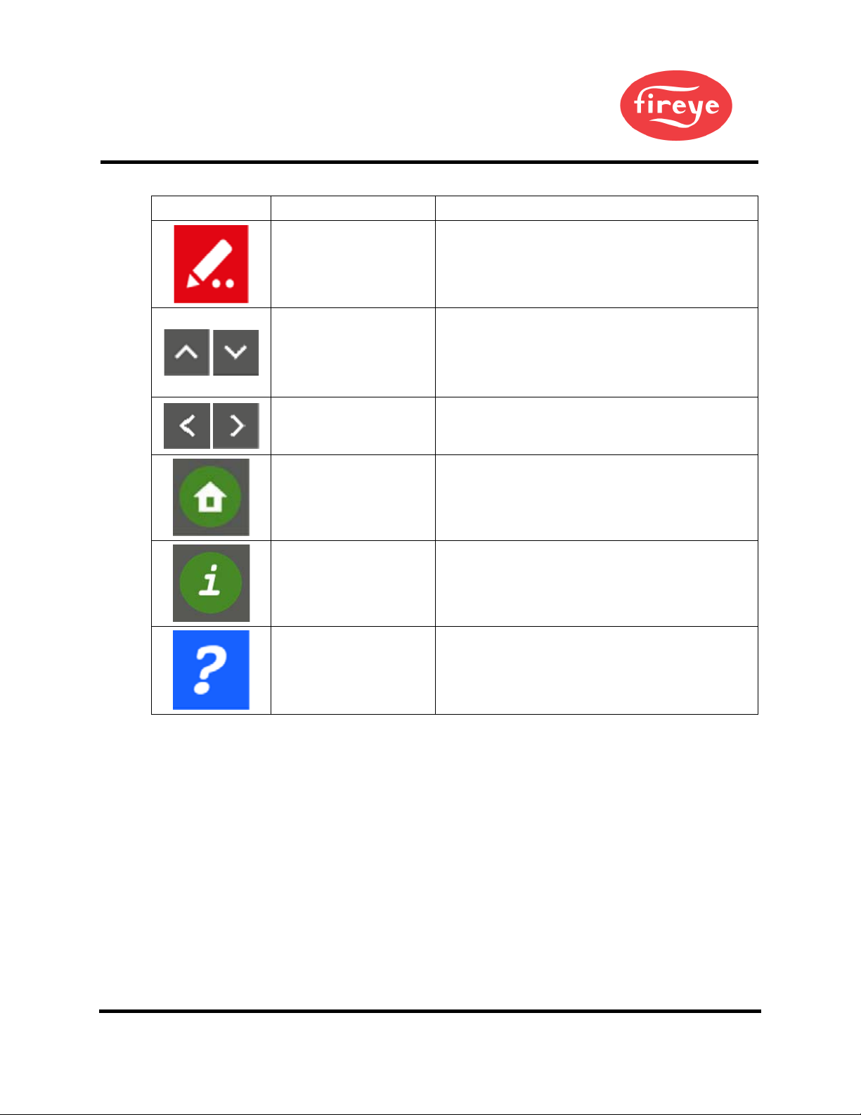
Quick Keys
Button
Key Name
Description
MODIFY/SAVE
In modify mode the button changes from red to green.
In this mode changes to a value are allowed. Pressing
again restores the button to red and saves the entry.
UP/DOWN
Used to navigate up and down through the menu
structure. When in modify mode these are used to
increment/decrement the values. Most values will
scroll from maximum to minimum or from minimum
to maximum in a loop.
BACK/NEXT
Used to move forward or backward through the menu
options. This only applies to what is on the second
(highlighted) line of the display.
HOME Used to return to the home display from any other
screen.
INFO Used to access the information screen where system
and diagnostic information can be accessed.
HELP Used to access the help legend on-screen showing the
meaning of each Quick Key.

12 © 2020 Carrier
CERTIFICATIONS NXD410TS
UL File # MP1537
The products have been designed for use in an industrial environment in compliance with the 2014/30/EU
EMC Directive.
The installation of these devices into the residential, commercial and light-industrial environments is
allowed only in the case that special measures are taken in order to ensure conformity to EN 61000-6-3.
The products are in compliance with the Restrictions on Certain Hazardous Substances (RoHS) Directive
2011/65/EU.
In compliance with the above regulations the products are CE marked.

© 2020 Carrier 13
NOTICE
When Fireye products are combined with equipment manufactured by others and/or integrated into systems
designed or manufactured by others, the Fireye warranty, as stated in its General Terms and Conditions of
Sale, pertains only to the Fireye products and not to any other equipment or to the combined system or its
overall performance.
WARRANTIES
FIREYE guarantees for one year from the date of installation or 18 months from date of manufacture of its
products to replace or repair (Fireye’s option) any product or part thereof (except lamps and photocells)
which is found defective in material or workmanship or which otherwise fails to conform to the description
of the product on the face of its sales order. THE FOREGOING IS IN LIEU OF ALL OTHER
WARRANTIES AND FIREYE MAKES NO WARRANTY OF MERCHANT¬ABILITY OR ANY
OTHER WARRANTY, EXPRESS OR IMPLIED. Except as specifically stated in these general terms
and conditions of sale, remedies with respect to any product or part number manufactured or sold by Fireye
shall be limited exclusively to the right to replacement or repair as above provided. In no event shall Fireye
be liable for consequential or special damages of any nature that may arise in connection with such product
or part.
Fireye, Inc.
3 Manchester Road
Derry, NH 03038
USA
www.fireye.com
NXD-4102
July 24, 2020
Supercedes NXD-4102 dated May 23, 2019
Supercedes NXDTS-4410 dated December 16, 2019
Other manuals for NXD410TS
2
Table of contents
Other Fireye Touchscreen manuals


Popular Touchscreen manuals by other brands

Johnson Controls
Johnson Controls Tyco HC2TCHPRO user manual

InFocus
InFocus INF5532AG Handling guide

XtendLan
XtendLan DPM-IP71R Operation manual

Elo TouchSystems
Elo TouchSystems 1515L Technische Daten

ViewSonic
ViewSonic ViewBoard IFP50 Series quick start guide

Digital Touch Systems
Digital Touch Systems DTS-5570KC user manual


