Squibb-Taylor A120MAN Instruction manual

A120MAN IOM 1 of 7www.squibbtaylor.com 1.800.345.8105
While this informaon is presented in good faith and believed to be accurate, Individuals using this literature must exercise their independent judgment in evaluang product selecon and determining
product appropriateness for their parcular purpose, system requirements and cercaons. The manufacturer reserves the right to change product designs and specicaons without noce.
.comwww.
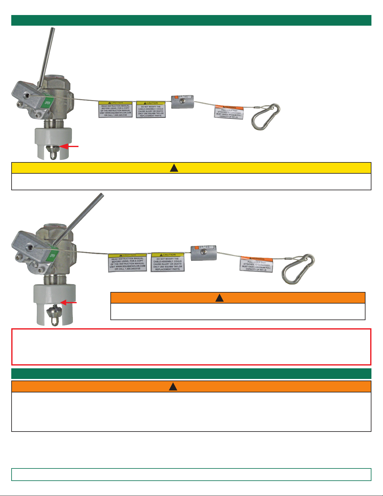
This instrucon manual covers installaon, operaon,
& maintenance for the A120MAN Manual Release for
1 1/4” (A120) & 1 1/2” (A125 & A15) internal valves
manufactured by Marshall Excelsior Co. for outdoor
Anhydrous Ammonia (NH3) applicaons.
.
FAILURE OR IMPROPER SELECTION OR IMPROPER USE OF THE PRODUCTS DESCRIBED HEREIN OR RELATED ITEMS CAN
CAUSE DEATH, PERSONAL INJURY AND PROPERTY DAMAGE.
• This document and other informaon from Squibb Taylor and authorized distributors provide product or system
opons for further invesgaon by users having technical experse.
• The user, through its own analysis and tesng, is solely responsible for making the nal selecon of the system and
components and assuring that all performance, endurance, maintenance, safety and warning requirements of the
applicaon are met. The user must analyze all aspects of the applicaon, follow applicable industry standards, and
follow the informaon concerning the product in the current product catalog and in any other materials provided
from Squibb Taylor or authorized distributors.
To the extent that Squibb Taylor or authorized distributors provide component or system opons based upon data or
specicaons provided by the user, the user is responsible for determining that such data and specicaons are suitable
and sucient for all applicaons and reasonably foreseeable uses of the components or systems.
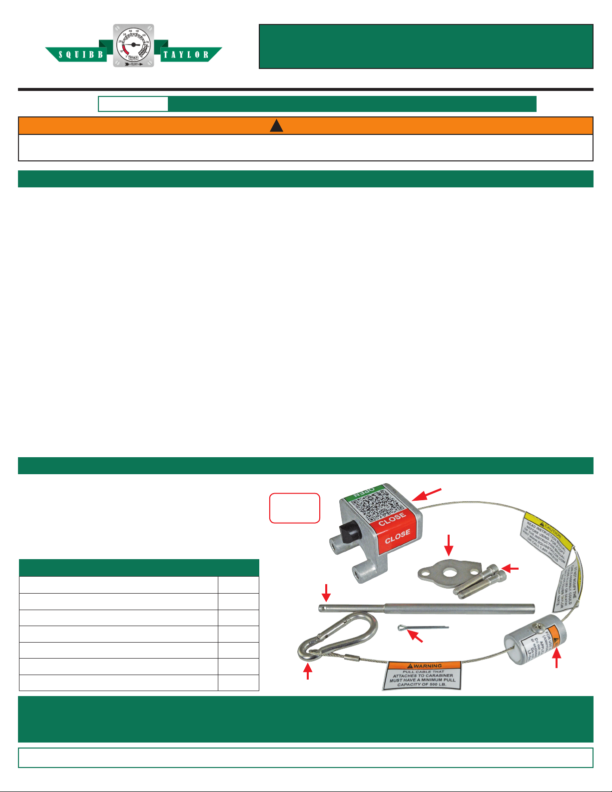
Manual Release with Break-Away Coupling 1 Pc.
Lever 1 Pc.
Plate 1 Pc.
Coer Pin 1 Pc.
Hex Mounng Cap Screws 2 Pc.
Carabinier 1 Pc.
Carabinier
Cap
Screws
Manual Release
Plate
Lever
Coer Pin
Break-Away
Coupling
Patent
Pending
!WARNING
ANHYDROUS AMMONIA APPLICATIONS ONLY.

A120MAN IOM 2 of 7www.squibbtaylor.com 1.800.345.8105
While this informaon is presented in good faith and believed to be accurate, Individuals using this literature must exercise their independent judgment in evaluang product selecon and determining
product appropriateness for their parcular purpose, system requirements and cercaons. The manufacturer reserves the right to change product designs and specicaons without noce.
1. Remove Plate & Cap Screws
from Gland Assembly. These
can be discarded.
Tool Used: 5/16” Allen Wrench
2. Install the Plate as shown.
Insert the thin end of the
Lever into the sha of the
Gland Assembly. Line up the
hole in Lever with the hole
in the Gland Assembly Sha
& insert the Coer Pin.
3. Secure the Lever to
the Gland Assembly
Sha by bending the
ends of the Coer
Pin back to secure it.
Verify that the Coer
Pin ends DO NOT rub
against the Plate.
C a p S c r e w s
& Plate
4. Aach the Manual Release onto
the valve. Insert the New Cap
Screws(2) into the Manual Release.
Line up the holes on the plate
with the holes on the valve. Line
up the Manual Release with the
holes on the plate & valve. Start
threading the screws into the
valve.
6. Test the Open operaon of the Manual
Release. Move the Lever to the right unl it
stops & release it. The plunger on the
Manual Release should have retracted
into the Release Housing to allow movement
of the lever. Once the Lever moves past the
plunger it should pop out to prevent it from
moving back to the Closed Posion.
Tool Used: 5/16” Allen Wrench
5. Secure the Manual
Release onto the
valve by ghtening
the Cap Screws(2)
with an Allen
Wrench to 25 - 30
Inch-Pounds of
Torque.
Hex
Screws
Lever In The
Open Posion
Lever In
The Closed
Posion
Pull The
Carabinier On
The End
7. Test the Close operaon of the Manual Release. Pull on
the Carabinier on the end of the cable unl the plunger
retracts & allowing the Lever to move to the Closed Posion.
Release the cable. Check the posion of the lever to make
sure that valve is closed. Check the plunger to make sure
that it has popped back out.
Plate
Coer
Pin
Bent
Ends
!WARNING
!WARNING
Lever In The
Open Posion
Lever In The
Closed Posion

A120MAN IOM 3 of 7www.squibbtaylor.com 1.800.345.8105
While this informaon is presented in good faith and believed to be accurate, Individuals using this literature must exercise their independent judgment in evaluang product selecon and determining
product appropriateness for their parcular purpose, system requirements and cercaons. The manufacturer reserves the right to change product designs and specicaons without noce.
1. See that the manual release is properly connected, works freely and is not worn.
2. Make sure there are no obstrucons or debris to block the valve and lever from closing.
3. Make sure that both cables move freely inside the Break-Away Coupling.
Open
Closed
Pull on the Loop End of the Cable. The plunger will retract to allow the lever to move. The closing
spring causes the valve to close.
The operator must always be aware of where the remote closure controls are located and know
how to operate the controls if an emergency requires valve closure. When nished, make a habit
of closing the internal valve from the remote closure point, thus checking to see that the control
actually is capable of closing the valve and operang correctly.
1. Always open the internal valve before opening any other valves in the line.
2. Move the lever to the half-open (rapid equalizaon) posion (Operaonal Schemac Figure 1, View #2 - A120,
A125, A15 IOM) to equalize pressure. When the main poppet clicks open, move the operang lever fully open.
3. Open other line valves slowly to avoid sudden surges which could slug the excess ow valve shut.
4. If the excess ow valve does close, close the nearest downstream valve. Move the internal valve’s operang
lever back to the rapid equalizing posion (outlined in step 2) and wait for the valve to click open. Then move
the operang lever fully open and slowly open the downstream valve.
!WARNING
!CAUTION
!WARNING

A120MAN IOM 4 of 7www.squibbtaylor.com 1.800.345.8105
While this informaon is presented in good faith and believed to be accurate, Individuals using this literature must exercise their independent judgment in evaluang product selecon and determining
product appropriateness for their parcular purpose, system requirements and cercaons. The manufacturer reserves the right to change product designs and specicaons without noce.
1. Remove Plate & Cap Screws
from Gland Assembly. These
can be discarded.
Tool Used: 5/16” Allen Wrench
2. Install the Plate as shown.
Insert the thin end of the
Lever into the sha of the
Gland Assembly. Line up the
hole in Lever with the hole
in the Gland Assembly Sha
& insert the Coer Pin.
3. Secure the Lever to
the Gland Assembly
Sha by bending the
ends of the Coer
Pin back to secure it.
Verify that the Coer
Pin ends DO NOT rub
against the Plate.
4. Aach the Manual Release onto
the valve. Insert the New Cap
Screws(2) into the Manual Release.
Line up the holes on the plate
with the holes on the valve. Line
up the Manual Release with the
holes on the plate & valve. Start
threading the screws into the
valve.
6. Test the Open operaon of the Manual
Release. Move the Lever to the right unl it
stops & release it. The plunger on the
Manual Release should have retracted
into the Release Housing to allow movement
of the lever. Once the Lever moves past the
plunger it should pop out to prevent it from
moving back to the Closed Posion.
Tool Used: 5/16” Allen Wrench
5. Secure the Manual
Release onto the
valve by ghtening
the Cap Screws(2)
with an Allen
Wrench to 25 - 30
Inch-Pounds of
Torque.
7. Test the Close operaon of the Manual Release. Pull on
the Carabinier on the end of the cable unl the plunger
retracts & allowing the Lever to move to the Closed Posion.
Release the cable. Check the posion of the lever to make
sure that valve is closed. Check the plunger to make sure
that it has popped back out.
Lever In The
Open Posion
Lever In The
Closed Posion
Lever In
The Closed
Posion
Lever In The
Open Posion
Pull The
Carabinier On
The End
Plate
Coer
Pin
C a p S c r e w s
& Plate
Bent
Ends
Hex
Screws
!WARNING
!WARNING

A120MAN IOM 5 of 7www.squibbtaylor.com 1.800.345.8105
While this informaon is presented in good faith and believed to be accurate, Individuals using this literature must exercise their independent judgment in evaluang product selecon and determining
product appropriateness for their parcular purpose, system requirements and cercaons. The manufacturer reserves the right to change product designs and specicaons without noce.
1. See that the manual release is properly connected, works freely and is not worn.
2. Make sure there are no obstrucons or debris to block the valve and lever from closing.
3. Make sure that both cables move freely inside the Break-Away Coupling.
Pull on the Loop End of the Cable. The plunger will retract to allow the lever to move. The closing
spring causes the valve to close.
The operator must always be aware of where the remote closure controls are located and know
how to operate the controls if an emergency requires valve closure. When nished, make a habit
of closing the internal valve from the remote closure point, thus checking to see that the control
actually is capable of closing the valve and operang correctly.
Open
1. Always open the internal valve before opening any other valves in the line.
2. Move the lever to the half-open (rapid equalizaon) posion (Operaonal Schemac Figure 1, View #2 - A120,
A125, A15 IOM) to equalize pressure. When the main poppet clicks open, move the operang lever fully open.
3. Open other line valves slowly to avoid sudden surges which could slug the excess ow valve shut.
4. If the excess ow valve does close, close the nearest downstream valve. Move the internal valve’s operang
lever back to the rapid equalizing posion (outlined in step 2) and wait for the valve to click open. Then move
the operang lever fully open and slowly open the downstream valve.
Closed
!WARNING
!CAUTION
!WARNING

A120MAN IOM 6 of 7www.squibbtaylor.com 1.800.345.8105
While this informaon is presented in good faith and believed to be accurate, Individuals using this literature must exercise their independent judgment in evaluang product selecon and determining
product appropriateness for their parcular purpose, system requirements and cercaons. The manufacturer reserves the right to change product designs and specicaons without noce.
1. Remove the Phillips
Head Screw from
the Break-Away
Coupling.
Phillips
Head
Screw
2. Remove the Break-Away Insert
from the Break-Away Coupling.
Grasp the outside of the
Coupling & push on the
Break-Away Insert unl it
is free of the Coupling.
3. Make sure that you
push the Break-Away
Insert out of the
Coupling on the side
that is aached to the
Manual Release.
4. Remove the Manual
Release cable from the
Break-Away Insert.
Manual Release
Cable
6. Discard the
Break-Away Insert.
Inspect the Crimped
Ends of the Cables
for wear or
deterioraon.
Discard
Break-Away Insert
8. Replace the Manual
Release Cable End
back into the new
Break-Away Insert.
7. Replace the Looped
Cable End back
into the New
Break-Away Insert.
9. Keep both cables
spread apart from
the center of the
Break-Away Insert.
Slide the Coupling over
the Break-Away Insert,
just enough to cover
the ends of the cables.
10. Line the Big Hole
in the Coupling
up with the hole
that is in the
Break-Away Insert.
Line Up Holes
11. Replace the Phillips
Head Screw as
shown. Tighten the
screw with a Phillips
Head Screw driver.
12. Check both cables.
Make sure that
each cable rotates
in & out.
Looped Cable Manual Release
Cable
Manual Release
Cable
5. Remove the Looped
Cable from the
Break-Away Insert.
Looped Cable
Cable Ends
!CAUTION

A120MAN IOM 7 of 7www.squibbtaylor.com 1.800.345.8105
While this informaon is presented in good faith and believed to be accurate, Individuals using this literature must exercise their independent judgment in evaluang product selecon and determining
product appropriateness for their parcular purpose, system requirements and cercaons. The manufacturer reserves the right to change product designs and specicaons without noce.
111901 A120-45AM 1 1/4” MNPT 1 1/4” FNPT Angle 45 GPM
111903 A120-45SM Straight
111906 A125-45AM
1 1/2” MNPT 1 1/4” FNPT
Angle 45 GPM
111908 A125-45SM Straight
111911 A125-60AM Angle 60 GPM
111913 A125-60SM Straight
111916 A15-45AM
1 1/2” MNPT 1 1/2” FNPT
Angle 45 GPM
111918 A15-45SM Straight
111921 A15-60AM Angle 60 GPM
111923 A15-60SM Straight
111904 A120-45A 1 1/4” MNPT 1 1/4” FNPT
A ng le
or
Straight
45 GPM
111909 A125-45A 1 1/2” MNPT 1 1/4” FNPT 45 GPM
111914 A125-60A 60 GPM
111919 A15-45A 1 1/2” MNPT 1 1/2” FNPT 45 GPM
111924 A15-60A 60 GPM
111930 LB-1 Latch Block Break-Away Assembly
111931 LC Lanyard & Carabinier Kit
111932 BAI Break-Away Insert
LB-1
LC
A120-45A
BAI
A120-45AM
Table of contents
Other Squibb-Taylor Industrial Equipment manuals