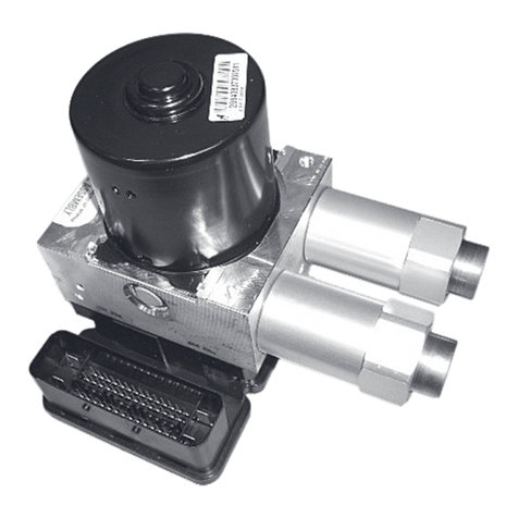
Squibb-Taylor AL344 Owner's manual

Form FVC 034—Rev 02 1 of 2
Installation, Operation, Maintenance,
Disassembly and Assembly Instructions
for Models AL344, AL345 & AL360, AL361
February 2008 Form FVC 034 - Rev 02
KEEP THIS DOCUMENT WITH THE PRODUCT UNTIL IT REACHES THE END USER.
Before installation or removal of Quick Acting Valves, the system must be purged completely of all product. Use proper safety equipment at all
times. An abundant supply of clean water must be readily available and easily accessible as a means of providing IMMEDIATE First Aid
treatment for exposure to ANHYDROUS AMMONIA. For LP-Gas service, follow NFPA / ANSI 58 Standard for the Storage and Handling of
Liquefied Petroleum Gases, plus all Local and State Safety Regulations. To insure long term safe operation, the manufacturer
recommends that under normal service conditions, this product should be inspected at least once every five (5) years and be repaired
or replaced as required. To prevent the accidental opening of any valve, never grasp or carry a valve by its handwheel or handle.
WARNING
CAUTION: Contact with or inhalation of Liquid Anhydrous Ammonia or LP-Gas, or their vapors, can cause serious injury or death.
Dispersement must be in accordance with local regulations.
For the proper handling and storage of Anhydrous Ammonia, refer to ANSI Standard K61.1.
For the proper handling and storage of Liquefied Petroleum Gas, refer to NFPA Pamphlet 58.
TOOLS REQUIRED: Safety Equipment (i.e. gloves, goggles, and clothing), 12” Pipe Wrench, 1/4” diameter Drift Pin, small Ball Peen Hammer,
7/16” Open-End or Boxed-End Wrench, Center Punch
Removal of Valve for Repair or Replacement
Step 1: Safety equipment (i.e. gloves, goggles, and clothing) must be worn before continuing to the next step.
Step 2: The Valve to be repaired must be in the CLOSED position, as shown in Figure 1. Make sure that all product has been removed from
the system prior to any disassembly.
NOTE: See ‘WARNING!’ at the top of this page.
INCORPORATED
DALLAS TEXAS
(214) 3
5
7
-
4
5
9
1
(
8
0
0
)
3
4
5
-
8
1
0
5
REFER TO FIGURE 1 FOR THE FOLLOWING STEPS:
Disassembly & Reassembly Procedure for Repair
Step 1: Remove the Valve from the service line or tank.
Step 2: With the Handle ○
1in the ‘CLOSED’ position, drive out the Handle Pivot Pin ○
2and remove the Handle .
Step 3: Remove the Handle Centering Ring ○
3from the Stem ○
4and keep it for re-assembly.
Step 4: Clean the part of the Stem that is sticking out of the top of the Bonnet ○
5and remove any burrs or debris.
Step 5: Secure the Valve Body ○
6in a bench-mounted vise, and remove the Bonnet ○
5by turning it in a counter-clockwise direction. The
Stem ○
4and the Disc Holder ○
7may come out with the Bonnet. If so, hold the Bonnet in an upright position and push the Stem
through the Bonnet.
NOTE: Take note of the position of the parts as the Stem is removed from the Bonnet. This will help in the reassembly of the Valve.
Step 6: Remove any Seals that may be on the Stem.
Step 7: Remove the Spring ○
8and the Centering Bushing ○
9from the Stem.
Step 8: Inspect the Stem for “pitting”, damage or undue wear. The Stem must be replaced if any one of these conditions exist. If the Stem is
in good condition, clean it thoroughly and keep it for reassembly.
Step 9: Place the Disc Holder ○
7in a bench-mounted vice and secure it just tightly enough to allow removal of the Jam Nut ○
10 , the Disc
Washer ○
11 , and the Disc ○
12 . Discard the old Disc and the Jam Nut.
Step 10: Install the new Disc, followed by the old Disc Washer, then the new Jam Nut. Tighten the Jam Nut, then, with the Jam Nut facing
upward, “stake” the thread and the Jam Nut at point ○
Ausing a sharp-pointed punch.
Step 11: Remove and discard the Seals from the Stem (Body/Bonnet Seal ○
13 , Seal Retainer ○
14 , Stem Seal ○
15 , Seal Sleeve ○
16 , and Seal
Washer ○
17 ).
Step 12: Inspect the Bonnet ○
5for thread damage.
Step 13: Clean the Bonnet, the Handle Assembly, and the Body thoroughly prior to beginning the reassembly process.
Step 14: Lubricate the new Seal Washer ○
17 with a small amount of the lubricant provided in the kit. Then use a pencil, or a round object, to
guide the Seal Washer into the counterbore of the Bonnet until it is bottomed out.
Step 15: Lubricate the Body/Bonnet O-Ring Seal ○
13 with a small amount of the lubricant provided in the kit. Then place the O-Ring over the
threads of the Bonnet, taking care not to cut the O-Ring.
Step 16: Secure the Valve Body ○
6in the vise. Use the 80 Grit abrasive cloth provided in the kit to remove any rust or pitting on the Seat
Surface ○
B. If the Seat Surface cannot be polished to near new-valve condition, the Valve Body must be replaced.
REFER TO FIGURE 1 FOR THE FOLLOWING

Form FVC 034—Rev 02 2 of 2
Step 17: Lubricate the Sealing Area ○
Cof the Stem and then place the Stem and the Disc Holder into the Valve Body.
Step 18: Install the Centering Bushing ○
9, larger diameter first, over the Stem until the Bushing rests on the Disc Holder.
Step 19: Place the Spring ○
8over the Stem and onto the Bushing.
Step 20: Place the new Seal Retainer ○
14 , larger diameter first, over the Stem and on top of the Spring.
Step 21: Lubricate the new Stem Seal ○
15 and slide it over the Stem, against the Seal Retainer.
Step 22: Lubricate the Seal Sleeve ○
16 and install it over the Stem, small end first, until it slips behind the Stem Seal.
Step 23: Lightly lubricate the threads of the Bonnet, then place the Bonnet (with the previously assembled Seal Washer) over the Stem.
Gently push the Bonnet downward while turning it in a clockwise direction to engage the threads of the Valve Body. Tighten the
Bonnet securely, using a 12” pipe wrench.
Step 24: Place the Handle Guide ○
3, with the angled diameter facing downward, over the end of the Stem.
Step 25: Secure the Valve Body in the vise as if it were laying on its side, and rotate the Stem until the cross hole is facing upward.
Step 26: Lay the Handle ○
1on its side and start the new Handle Pivot Pin ○
2into one side.
Step 27: With the Pin pointing upward and the Handle in the ‘CLOSED’ position, align the Pin with the Stem’s cross hole, and drive the Pin
through the Stem and into the other side wall of the Handle. The Pin should be flush on both sides of the Handle.
Step 28: LATCH TEST
A) Open and close the Handle three (3) times.
B) In the ‘CLOSED’ position, spin the Handle around three (3) times.
C) In the ‘OPEN’ position, rotate the Handle three (3) full revolutions. (This action will “seat” the Stem Seals.)
D) Check the camming action by opening the Valve Handle fully and then pushing slowly on the Handle, allowing it to snap
shut with its own cam action. NOTE: When in the ‘CLOSED’ position, there must be at least 1/16” gap between the
Handle and the Handle Bearing ○
18 .
Step 29: PRESSURE TEST
After the Latch Test is complete, with the Valve in the ‘CLOSED’ position, the seal between the Valve Seat and Stem Seal
(surface ○
B) should be ‘bubble-tight’, when pressurized at the inlet side to 75 PSIG with air and submerged in water.
Step 1: To open the Valve, depress the top surface of the Handle Safety Lock at ○
Dand lift the Handle to its vertical position. When the
Valve is in the full ‘OPEN’ position, the heel of the Handle with rest squarely on the Handle Bearing ○
18 and the Handle will be
cammed over slightly past the center of the Valve.
Step 2: To close the Valve, tap the Handle in the closing direction. The Handle will pivot in a ‘Quick Acting’ manner to the CLOSED position.
The closing spring action of the Valve Assembly is designed to force the Handle Safety Lock ○
19 to lock under the Bonnet Flange (see
note in FIGURE 1), therefore preventing accidental opening of the Valve.
WARNING! If the Valve is not allowed to snap shut under its own spring action, but is instead closed slowly by
holding the Handle as it is moved toward the CLOSED position, the Handle may not continue to its
STOP position. Make sure the handle Safety Lock ○
19 is engaged under the Bonnet Flange when the
Valve is in the CLOSED position.
Disassembly & Reassembly Procedure for Repair (cont’d.) REFER TO FIGURE 1 FOR THE FOLLOWING
Operation of the Quick Acting Valve REFER TO FIGURE 1 FOR THE FOLLOWING
FIGURE 1
This manual suits for next models
3
Table of contents
Other Squibb-Taylor Industrial Equipment manuals
