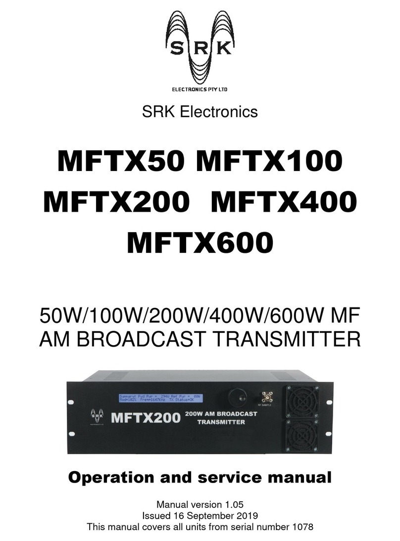
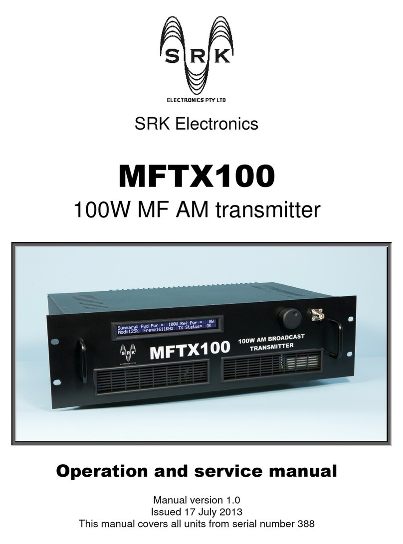
SRK Electronics MFTX100 Operation manual

SRK Electronics
MFTX100 MFTX200
MFTX400 MFTX600
100W/200W/400W/600W MF AM
BROADCAST TRANSMITTER
Operation and service manual
Manual version 1.04
Issued 6 November 2017
This manual covers all units from serial number 889

MFTX AM TRANSMITTERS
SRK Electronics
2
Contents
1. MFTX QUICK START GUIDE ............................................................................................................. 5
2. OVERVIEW ...................................................................................................................................... 7
3. SPECIFICATIONS .............................................................................................................................. 8
4. WARRANTY ................................................................................................................................... 12
5. UNPACKING .................................................................................................................................. 13
6. INSTA ATION .............................................................................................................................. 14
6.1 GENERAL ........................................................................................................................................... 14
6.2 ENVIRONMENTAL ................................................................................................................................ 15
6.3 ELECTRICAL SUPPLY .............................................................................................................................. 16
6.4 EARTHING .......................................................................................................................................... 17
6.5 ANTENNA .......................................................................................................................................... 18
6.6 AUDIO FEED ....................................................................................................................................... 19
6.7 EXTERNAL PO ER SUPPLY (MFTX600 ONLY) .......................................................................................... 20
7. EXTERNA VIEWS .......................................................................................................................... 21
7.1 FRONT PANEL ..................................................................................................................................... 21
7.1.1 (1) Display ............................................................................................................................. 21
7.1.2 (2) Control knob .................................................................................................................... 21
7.1.3 (3) RF sample connector ....................................................................................................... 21
7.1.4 (4) Air vents ........................................................................................................................... 21
7.2 REAR PANEL ....................................................................................................................................... 22
7.2.1 (1) Rig t/mono audio input connector ................................................................................. 22
7.2.2 (2) Left audio input ............................................................................................................... 22
7.2.3 (3) RF output connector ........................................................................................................ 22
7.2.4 (4) Mains input connector ..................................................................................................... 22
7.2.5 (5) Eart stud ........................................................................................................................ 22
7.2.6 (6) Air vent ............................................................................................................................ 22
7.2.7 (7) Analogue remote control barrier strip ............................................................................. 23
7.2.8 (8) Serial remote control connector ...................................................................................... 23
7.2.9 (9) Heatsink ........................................................................................................................... 23
8. TRANSMITTER OPERATION ........................................................................................................... 24
8.1 RF FUNCTIONS ................................................................................................................................... 25
8.1.1 Set RF power ......................................................................................................................... 25
8.1.2 Forward and reflected power metering ................................................................................ 25
8.1.3 Carrier frequency .................................................................................................................. 26
8.1.4 Carrier reference ................................................................................................................... 26
8.2 AUDIO FUNCTIONS .............................................................................................................................. 28
8.2.1 Gain control .......................................................................................................................... 28
8.2.2 Modulation metering ............................................................................................................ 28
8.2.3 Compressor ........................................................................................................................... 28
8.2.4 Limiter ................................................................................................................................... 28
8.2.5 Low Pass Filter ...................................................................................................................... 29
8.2.6 Stereo .................................................................................................................................... 29
8.3 TIME FUNCTIONS ................................................................................................................................. 30
8.3.1 Clock...................................................................................................................................... 30

MFTX AM TRANSMITTERS
SRK Electronics
3
8.3.2 Nig t-time power .................................................................................................................. 30
9. FRONT PANE OPERATION ............................................................................................................ 31
9.1 SUMMARY SCREEN .............................................................................................................................. 32
9.2 RF MENU .......................................................................................................................................... 33
9.2.1 Setting carrier power ............................................................................................................ 33
9.2.2 Setting carrier frequency ...................................................................................................... 33
9.2.3 Turning RF on and off ........................................................................................................... 34
9.2.4 Reading forward and reflected power .................................................................................. 34
9.3 AUDIO MENU ..................................................................................................................................... 35
9.3.1 Setting audio gain ................................................................................................................. 35
9.3.2 Reading modulation dept ................................................................................................... 35
9.3.3 Enabling and disabling t e audio low pass filter (LPF) ......................................................... 35
9.3.4 Enabling and disabling audio compressor ............................................................................ 36
9.3.5 Enabling and disabling stereo ............................................................................................... 36
9.4 LIMITER MENU .................................................................................................................................... 37
9.4.1 Enabling and disabling t e limiter ........................................................................................ 37
9.4.2 Setting t e positive limit level ............................................................................................... 37
9.4.3 Setting t e negative limit level ............................................................................................. 38
9.5 LPF MENU ......................................................................................................................................... 39
9.5.1 Setting filter type .................................................................................................................. 39
9.5.2 Setting cutoff frequency ....................................................................................................... 39
9.6 RF PA1 – RF PA6 .............................................................................................................................. 40
9.7 ALARMS ............................................................................................................................................ 41
9.8 DATE/TIME MENU ............................................................................................................................... 42
9.8.1 Reading elapsed days ........................................................................................................... 42
9.8.2 Setting date and time ........................................................................................................... 42
9.9 NIGHT PO ER MENU ........................................................................................................................... 43
9.9.1 Enabling and disabling nig t-time power switc ing ............................................................. 43
9.9.2 Setting nig t-time power start and stop times ..................................................................... 43
9.9.3 Setting nig t-time power ...................................................................................................... 43
9.10 CARRIER REFERENCE ........................................................................................................................ 44
9.11 UNIT DATA .................................................................................................................................... 45
10. REMOTE CONTRO ........................................................................................................................ 46
10.1 ANALOGUE REMOTE CONTROL .......................................................................................................... 47
10.1.1 Interlock ................................................................................................................................ 47
10.1.2 TX OK relay ............................................................................................................................ 47
10.1.3 Audio OK relay ...................................................................................................................... 47
10.1.4 Alarm tally output ................................................................................................................. 48
10.2 SERIAL REMOTE CONTROL................................................................................................................. 49
10.2.1 Serial command list (alp abetical) ....................................................................................... 49
10.2.2 Serial command list (by function) ......................................................................................... 51
11. A ARMS ........................................................................................................................................ 53
11.1 S R ALARM AND FLASHOVER ALARM ................................................................................................ 54
11.2 INTERLOCK ALARM .......................................................................................................................... 55
11.3 GEN ALARM .................................................................................................................................. 56
11.4 TEMPERATURE ALARM ..................................................................................................................... 57
11.5 AUDIO ALARM ............................................................................................................................... 58
12. MAINTENANCE ............................................................................................................................. 59
12.1 EXAMPLE LOG SHEET ....................................................................................................................... 60

MFTX AM TRANSMITTERS
SRK Electronics
4
13. ADJUSTMENTS .............................................................................................................................. 61
13.1 POT1, FOR ARD PO ER CALIBRATION .............................................................................................. 61
13.2 POT2, REFLECTED PO ER THRESHOLD ............................................................................................... 61
13.3 POT3, REFLECTED PO ER CALIBRATION ............................................................................................. 61
13.4 POT4, CARRIER FREQUENCY FINE ADJUSTMENT .................................................................................... 61
13.5 POT5, LCD CONTRAST.................................................................................................................... 61
13.6 POT6, ALARM TALLY ANALOGUE VOLTAGE TRIM ................................................................................... 61
13.7 DC SUPPLY ADJUSTMENT ................................................................................................................. 62
13.8 DIRECTIONAL COUPLER NULL ............................................................................................................. 62
14. CIRCUIT DESCRIPTION ................................................................................................................... 63
14.1 THEORY OF OPERATION .................................................................................................................... 63
14.2 BLOCK DIAGRAMS ........................................................................................................................... 65
14.2.1 MFTX100 block diagram ....................................................................................................... 65
14.2.2 MFTX200 block diagram ....................................................................................................... 66
14.2.3 MFTX400 block diagram ....................................................................................................... 67
14.2.4 MFTX600 block diagram ....................................................................................................... 68
14.3 CONTROL UNIT ............................................................................................................................... 69
14.4 RF PO ER AMPLIFIER ...................................................................................................................... 71
14.5 OUTPUT FILTER .............................................................................................................................. 72
15. ABBREVIATIONS............................................................................................................................ 73
16. BI OF MATERIA S ....................................................................................................................... 75
16.1 MFTX100 TOP LEVEL ..................................................................................................................... 75
16.2 MFTX200 TOP LEVEL ..................................................................................................................... 76
16.3 MFTX400 TOP LEVEL ..................................................................................................................... 77
16.4 MFTX600 TOP LEVEL ..................................................................................................................... 78
16.5 CONTROL UNIT ............................................................................................................................... 79
16.6 RF PO ER AMPLIFIER ...................................................................................................................... 80
16.7 MFTX100 OUTPUT FILTER ............................................................................................................... 81
16.8 MFTX200 OUTPUT FILTER .............................................................................................................. 82
16.9 MFTX400 OUTPUT FILTER .............................................................................................................. 83
16.10 MFTX600 OUTPUT FILTER .............................................................................................................. 84
17. SCHEMATICS ................................................................................................................................. 85
17.1 MFTX100 OVERALL SCHEMATIC ...................................................................................................... 85
17.2 MFTX200 OVERALL SCHEMATIC ...................................................................................................... 86
17.3 MFTX400 OVERALL SCHEMATIC ...................................................................................................... 87
17.4 MFTX600 OVERALL SCHEMATIC ...................................................................................................... 88
17.5 CONTROL UNIT SCHEMATIC .............................................................................................................. 89
17.6 RF PO ER AMPLIFIER SCHEMATIC .................................................................................................... 97
18. PCB AYOUTS ................................................................................................................................ 98
19. CHANGE HISTORY ......................................................................................................................... 99

MFTX AM TRANSMITTERS
SRK Electronics
5
1. MFTX Quick Start Guide
We strongly urge our customers to read this manual before attempting to use the
transmitter. The MFTX range of MF transmitters incorporate functionality and
features not normally found in equipment of this type and a thorough
understanding if these will lead to easier commissioning and use.
However, we understand that our customers are busy people with a high level of
technical competence. So with this in mind the following is a quick procedure to
get your transmitter up and running:
1. Unpack the transmitter. Please retain the packing.
2. The MFTX600 consists of the transmitter proper and an external power supply. Both
units are rack mountable. The power supply is designed to sit on top of the transmitter
(for standalone configurations) or immediately above the transmitter (if rack mounted).
All other models use an internal power supply.
3. Please allow adequate front-to-back air flow. No additional ventilation space is needed.
4. Depending on the power supply configuration, 0ne, two or three supplies may be
included in the power supply (MFTX600 only). There are three separate mains feeds to
the power supply from the transmitter. The DC output of the power supply is fed back
to the transmitter on the blue Anderson connector. This must be fully engaged into the
mating connector on the rear of the transmitter. This may require some force (which is
normal)
5. Antenna connection is made via the N connector on the rear of the transmitter.
6. Audio connection is made by the three pin XLR connector on the rear of the transmitter.
This is electronically balanced so unbalanced audio feeds should connect pins 1 and 3 as
return.
7. Earth connection can be made to the M6 stud on the rear of the transmitter.
8. Mains is supplied to the transmitter via the IEC cable (supplied).
9. All manual controls are accessible via the single front panel knob. This is rotated to
select the menu or parameter to be read or modified. A flashing arrow on the LCD
points to the current parameter. Pressing the knob will cause that parameter to flash
and rotating the knob will allow that parameter to be modified. Once set to the desired
value, pressing the knob again will cause the value to be stored in NV RAM and will
allow another parameter to be selected.

MFTX AM TRANSMITTERS
SRK Electronics
6
10. This transmitter has been shipped with the following settings:
a. RF = off
b. Set power = maximum
c. Audio gain = 20%
d. LPF = in
e. LPF type = Bessel
f. LPF cutoff = 8.8KHz
g. Compressor = off
h. Limiter = on
i. Positive limit/negative limit = gives -95/+125% limit
Note that the positive and negative limit values are arbitrary units, not
percent.
j. Night time power = Disabled, 96
k. Reference = internal
l. Location = Melbourne
m. Front panel = enabled
11. These represent a typical setup.
12. Turn on the transmitter by the circuit breaker on the rear panel (MFTX600 and 400) or
by plugging in the mains cord (MFTX200 and 100).
13. All fans should start and the LCD should light, showing the summary screen.
14. You can now change any settings as desired using the front panel control.
15. Apply program audio and set the audio gain that gives the desired modulation depth.
16. Adjust set power to give the desired carrier rest power.
17. Turn on the RF.
18. The forward power meter should indicate the presence of RF output. Note that the
forward and reflected power measurements are true average power reading. Also that
there is no forward power control loop. Therefore discrepancies between the set power
and indicated forward power will almost certainly occur, especially if running into a
reflective load. In practice, set power should be adjusted to give the desired forward
power.

MFTX AM TRANSMITTERS
SRK Electronics
7
2. Overview
The MFTX100, MFTX200, MFTX400 and MFTX600 are 100W, 200W, 400W and
600W carrier rest AM transmitters designed for continuous unattended service in
MF broadcast applications.
Amongst others, the MFTX transmitters have the following features:
•10-100W, 20-200W, 40-400W and 60-600W carrier rest power
•Power efficient design
•Pseudo frequency agile
•Electronically balanced professional audio inputs
•In-built audio processor
•Over SWR and over temperature protection
•Loss of audio alarm
•Automatic recovery from alarm conditions – no user intervention
required
•Night-time power reduction
•Alarm tally – records nature and time of up to 4000 alarms
•Safety interlock input
•Transmitter OK and audio OK relay outputs
•Serial remote control port
•Elapsed operational days counter
•Unity power factor mains load
•RF sample port

MFTX AM TRANSMITTERS
SRK Electronics
8
3. Specifications
MFTX100
RF output power (0% mod) 10-100W, settable in 1W steps
RF output power (peak) 500W
RF output connector N female
Harmonics and spurious >-65dBc
Factory set frequency range 531-1701KHz
User set frequency range within ±3% of factory setting
Carrier stability +/-2Hz
Audio input level 0.24-2.4V RMS
Audio frequency response 10Hz-13KHz
Audio distortion <0.5% THD
Audio signal-to-noise ratio >60dB
Squarewave tilt @40Hz 5%
Squarewave overshoot 2%
Carrier shift <5%
Modulation capability 125% positive peak modulation
Audio input impedance >10,000 ohms
Audio input connectors XLR 3 pin female
SWR alarm threshold 10W
Over temperature trip 85°C
Audio alarm period 30 seconds
Alarm tally capacity 4000 alarm events
Power input (100W, 0% mod) 170W
Supply voltage 105-264VAC
Supply connector IEC 3 pin male
Earth stud M6
Cooling Convection/Forced air
Size 2U rack case, 300mm deep
Weight <10Kg
Ambient temperature -5°C to +50°C
Humidity 0 to 95% RH, non-condensing
Altitude 0 to 4000m above sea level

MFTX AM TRANSMITTERS
SRK Electronics
9
MFTX200
RF output power (0% mod) 20-200W, settable in 2W steps
RF output power (peak) 1000W
RF output connector N female
Harmonics and spurious >-65dBc
Factory set frequency range 531-1701KHz
User set frequency range within ±3% of factory setting
Carrier stability +/-2Hz
Audio input level 0.24-2.4V RMS
Audio frequency response 10Hz-13KHz
Audio distortion <0.5% THD
Audio signal-to-noise ratio >60dB
Squarewave tilt @40Hz 5%
Squarewave overshoot 2%
Carrier shift <5%
Modulation capability 125% positive peak modulation
Audio input impedance >10,000 ohms
Audio input connectors XLR 3 pin female
SWR alarm threshold 20W
Over temperature trip 85°C
Audio alarm period 30 seconds
Alarm tally capacity 4000 alarm events
Power input (200W, 0% mod) 400W
Supply voltage 105-264VAC
Supply connector IEC 3 pin male
Earth stud M6
Cooling Convection/Forced air
Size 3U rack case, 300mm deep
Weight <10Kg
Ambient temperature -5°C to +50°C
Humidity 0 to 95% RH, non-condensing
Altitude 0 to 4000m above sea level

MFTX AM TRANSMITTERS
SRK Electronics
10
MFTX400
RF output power (0% mod) 40-400W, settable in 4W steps
RF output power (peak) 2000W
RF output connector N female
Harmonics and spurious >-65dBc
Factory set frequency range 531-1701KHz
User set frequency range within ±3% of factory setting
Carrier stability +/-2Hz
Audio input level 0.24-2.4V RMS
Audio frequency response 10Hz-13KHz
Audio distortion <0.5% THD
Audio signal-to-noise ratio >60dB
Squarewave tilt @40Hz 5%
Squarewave overshoot 2%
Carrier shift <5%
Modulation capability 125% positive peak modulation
Audio input impedance >10,000 ohms
Audio input connectors XLR 3 pin female
SWR alarm threshold 40W
Over temperature trip 85°C
Audio alarm period 30 seconds
Alarm tally capacity 4000 alarm events
Power input (400W, 0% mod) 800W
Supply voltage 105-264VAC
Supply connector IEC 3 pin male
Earth stud M6
Cooling Forced air
Size 5U rack case, 450mm deep
Weight <15Kg
Ambient temperature -5°C to +50°C
Humidity 0 to 95% RH, non-condensing
Altitude 0 to 4000m above sea level

MFTX AM TRANSMITTERS
SRK Electronics
11
MFTX600
RF output power (0% mod) 60-600W, settable in 6W steps
RF output power (peak) 3000W
RF output connector N female
Harmonics and spurious >-65dBc
Factory set frequency range 531-1701KHz
User set frequency range within ±3% of factory setting
Carrier stability +/-2Hz
Audio input level 0.24-2.4V RMS
Audio frequency response 10Hz-13KHz
Audio distortion <0.5% THD
Audio signal-to-noise ratio >60dB
Squarewave tilt @40Hz 5%
Squarewave overshoot 2%
Carrier shift <5%
Modulation capability 125% positive peak modulation
Audio input impedance >10,000 ohms
Audio input connectors XLR 3 pin female
SWR alarm threshold 60W
Over temperature trip 85°C
Audio alarm period 30 seconds
Alarm tally capacity 4000 alarm events
Power input (600W, 0% mod) 1200W
Supply voltage 105-264VAC
Supply connector IEC 3 pin male
Earth stud M6
Cooling Forced air
Size 7U rack case, 450mm deep
Weight <25Kg
Ambient temperature -5°C to +50°C
Humidity 0 to 95% RH, non-condensing
Altitude 0 to 4000m above sea level

MFTX AM TRANSMITTERS
SRK Electronics
12
4. Warranty
SRK warrants that the equipment is newly manufactured and is free of any
defects in materials and workmanship.
SRK shall rectify any defect in the equipment which is notified in writing to SRK
by the Customer within the period of 3 years after the date of acceptance where
such defect renders the equipment unable to conform to the specifications and
configuration prescribed in this manual.
SRK shall be responsible for all costs of rectification of such defects save for
freight and travel costs.
SRK warrants that any replacement parts provided to the Customer are newly
manufactured and are free from defects in materials and workmanship. If the
replacement parts are found to be defective during a period of 90 days after
installation of those parts, they shall be rectified or replaced at SRK's expense.
SRK shall not be liable for defects resulting from improper use of the equipment,
whether by the Customer or by a third party or from damage caused to the
equipment by external influences, including, but not limited to lightning strike,
power surges or irregularity, ingress of water or other moisture, impact or
temperature fluctuations in excess of the tolerances set out in the specifications.

MFTX AM TRANSMITTERS
SRK Electronics
13
5. Unpacking
This section details the way in which the transmitter should be unpacked upon
receipt by the customer.
Upon receipt the transmitter should be visually inspected to ensure that no
damage has occurred in transit.
The packing should be stored and used should it be necessary to return the
transmitter to the manufacturer.
The customer should ensure that all items are present and then store them in a
safe place.

MFTX AM TRANSMITTERS
SRK Electronics
14
6. Installation
6.1 General
This section describes the installation and infrastructure requirements for the
transmitter. Departure from the instructions contained herein may void any
warranty provided by SRK.
The MFTX100 has been designed to be mounted in a standard 19” rack frame,
where it will occupy 2 rack units.
The MFTX200 has been designed to be mounted in a standard 19” rack frame,
where it will occupy 3 rack units.
The MFTX400 has been designed to be mounted in a standard 19” rack frame,
where it will occupy 5 rack units.
The MFTX600 has been designed to be mounted in a standard 19” rack frame,
where it will occupy 6 to 8 rack units, depending upon power supply options
supplied.
However, the transmitter may also be used in a free standing situation, so long
as all other requirements are met as below.

MFTX AM TRANSMITTERS
SRK Electronics
15
6.2 Environmental
The transmitter is intended for indoor use.
The transmitter should be protected from rainfall and direct sunlight, extremes of
temperature and humidity and from conditions of high dust levels.
The transmitter shall not be operated at altitudes in excess of 4000m above sea
level.
The transmitter must be installed on a flat, stable surface.
The transmitter must be installed in the upright position.
The transmitter must be installed in a location free from vermin and the ingress of
other animals.
The transmitter shall not be installed in locations prone to flooding.
All ventilation orifices must be clear to allow adequate air flow.
If installed in a rack, the equipment immediately above or below the transmitter
should not overhang the fins of the heatsink on the rear of the transmitter
(MFTX100 and 200 only).

MFTX AM TRANSMITTERS
SRK Electronics
16
6.3 Electrical supply
The electrical supply to the transmitter must be of the voltage, form and
frequency described in the specifications.
All electrical wiring must be carried out in accordance with local laws, standards
and regulations.
If power supply voltages regularly fall outside specifications then a voltage
regulator must be installed between the supply inlet and the transmitter.
Whilst the transmitter does include live-neutral mains supply MOV protection,
external three way protection is also recommended for long term reliability.

MFTX AM TRANSMITTERS
SRK Electronics
17
6.4 Earthing
Adequate earthing of the transmitter is vital to ensure long term reliability and
user safety.
The electrical supply must be earthed, via the earthing pin of the IEC connector.
In countries where power outlet earthing is only optional, an earthed outlet must
be used.
A separate, independent, earth is required for the transmitter/antenna system
and must be connected to the earthing point indicated on the rear of the
transmitter.
The cable used to connect this earth should be as thick as possible, with 8 AWG
being the smallest size acceptable. Where possible, broad earthing band should
be used.
In addition to the earth connection to the transmitter, the outer conductor of the
coax feed to the antenna should be connected to the earth, as indicated below.
The earth itself must be of high quality buried copper, at least 1.5m deep and
preferably in ground that is habitually humid (eg, the base of a gutter down pipe).

MFTX AM TRANSMITTERS
SRK Electronics
18
6.5 Antenna
The antenna load connected to the transmitter must be tuned to minimise
reflections. Whilst the transmitter is designed to withstand high levels of
reflection for short periods, continually high levels of reflected power will degrade
the long term reliability of the transmitter. Operating SWR should be kept to
below 1.9:1.

MFTX AM TRANSMITTERS
SRK Electronics
19
6.6 Audio feed
In situations where the audio feed to the transmitter is over any form of land line,
suitable protection must be included external to the transmitter to ensure voltage
transients do not enter the transmitter. These may be in the form of high power
zener diodes and/or gas discharge tubes.

MFTX AM TRANSMITTERS
SRK Electronics
20
6.7 External Power Supply (MFTX600 only)
The MFTX600 uses an external power supply. This is designed to sit
immediately above the transmitter.
There are various power supply options including multiple redundant switch
mode supplies or a linear supply.
The MFTX600 has capacity for up to three supplies and there is a switched
mains supply for each (controlled by the main breaker).
The nominal 50VDC from the supply is fed back into the transmitter via the blue
Anderson connector. Note that this connector must be fully engaged and this
may require some force. This is normal.
Other manuals for MFTX100
1
This manual suits for next models
3
Table of contents
Other SRK Electronics Transmitter manuals
Popular Transmitter manuals by other brands
H3C
H3C TC01 quick start

DME
DME SRB-406 Operation manual
MTS Sensors
MTS Sensors Level Plus M Series Operation and installation manual

Kanardia
Kanardia Daqu installation manual
Becker
Becker Centronic EasyControl EC415A-III Assembly and operating instructions
Honeywell
Honeywell SMV800 Quick start installation guide
