Specifications are subject to change without notice.
AR006664 and AR004418 interior transmitters
with analog outputs
PRODUCT DESCRIPTION
Programmable interior transmitters with 4 - 20 mA or 0 - 10 V outputs are designed for measurement of CO2concentration in air and
for measurement of air temperature in exacting interiors in building energy management and HVAC systems.
The CO2concentration is measured using the dual wavelength NDIR sensor with multiple point adjustment. This principle compensates
aging of the sensing elements and guarantees outstanding high reliability and long-term stability of the measurement.
Measured valuesare displayed on a two-line LCD display. The device is also equipped with three-color LED for visual indication of the
CO2concentration. Using TSensor software (see www.guilcor.com) you can set up measuring range of device output, measurement
mode of CO2concentration and limits of CO2LED indication. For device connection to USB port of PC is used AR006576 cable
(optional accessories). The connector for AR006576 cable connection is situated on the front part of the device near the info-button.
Transmitters are designed for easy installation on ordinary KU68 wiring boxes with using two enclosed mounting screws.
type * output measured values construction mounting
AR006664 2 x 4-20mA T + CO2ambient air wall
AR004418 2 x 0-10V T + CO2 ambient air wall
f
* models marked TxxxxZare custom - specified devices T…temperature, CO2…concentration of CO2in air
INSTALATION AND OPERATION
For correct function there is necessary to find proper device place. It shouldn’t be placed at places where it can be affected by sunshine,
near radiators, heating elements and other heat sources, air handlers, windows, doors, into racks and shelves and similar places. For
buildings with less thermal insulation there is not suitable to place them on external walls of building. If there are communication conductors
placed into conduit, there is strongly recommended make it caulk, to restrict air flow around device.
Current outputs 4 - 20 mA (transmitter AR006664) can be galvanically isolated or galvanically non-isolated. Configuration jumpers
(see schematic diagram) are located on the front part of the device. Voltage outputs 0 - 10 V (transmitter AR004418) are not
galvanically isolated.
Firstly mount back part of device onto wiring box with two holding screws. Connect cables to terminals and finally insert front part of
device (installation procedure see next page). For transmitter connection it is recommended to use shielded cable. Maximum cable
length of the current loop is 1200m, maximum voltage output cable length is 15m. All cables should be located as far as possible
from potential interference sources.
After powering on the device starts the internal test. During this time LCD display shows ---- instead of CO2concentration value.
Devices don´t require special operation and maintenance. We recommend you periodic calibration for measurement accuracy validation.
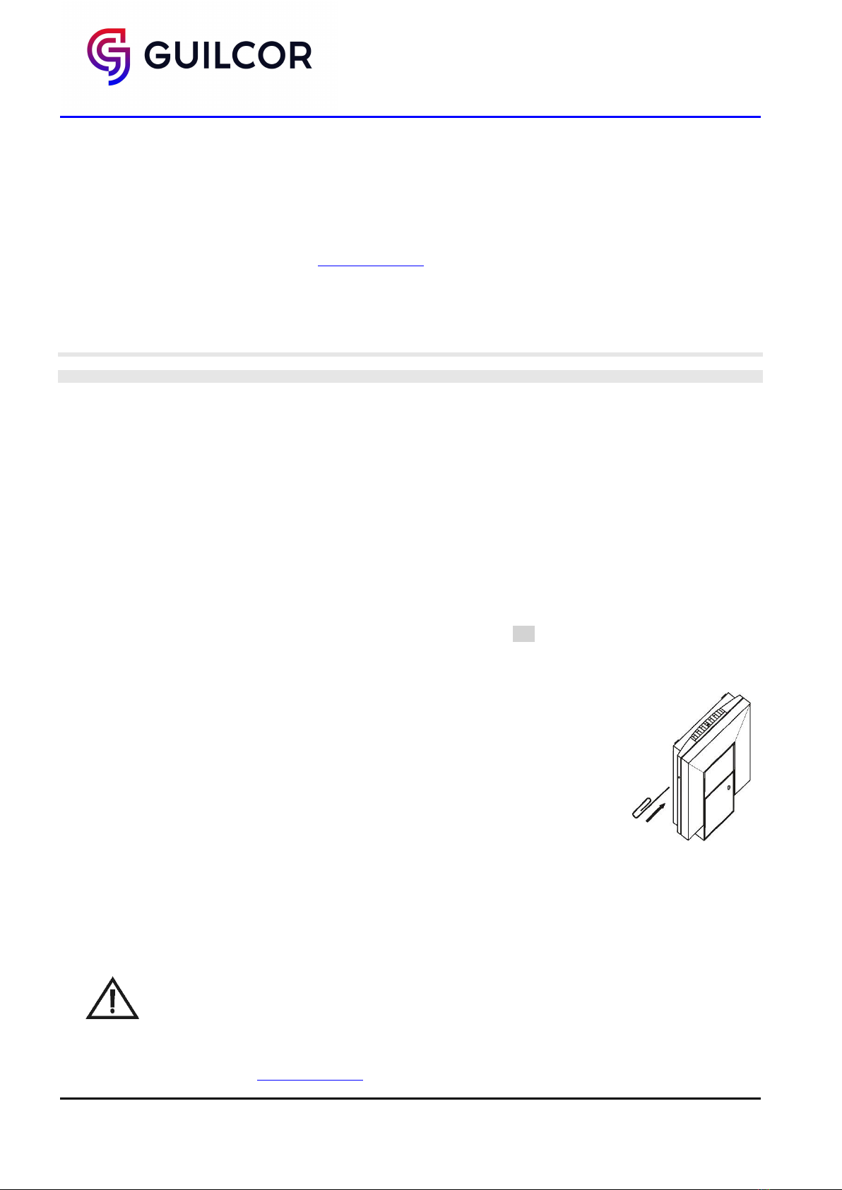
INFO MODE
The output range settings can be verified without a use of the computer by pressing button on the left side
of the device (see picture). For button pressing use thin instrument (paper clip etc.). First short press shows
low range and type of measured value for I1 output. Next button press shows values for upper scale limit
(the same channel, the same value). I2 output settings are displayed similarly. No measurement and
communication is possible during info mode. If device stays in info mode for longer than 15 s, device
automatically returns to measuring cycle.
ERROR STATES
Device continuously checks its state during operation and if an error appears, it is displayed relevant code:
Err 2 - CO2concentration or temperature measurement error occurred
Err 0, Err 1, Err 3 and Err 4 - it is a serious error, please contact distributor of the device
SAFETY INSTRUCTIONS
-Don’t connect or disconnect transmitter while power supply voltage is on.
- Don´t use the device in an explosive environment.
- Devices are not designed for locations with chemically aggressive environment.
- Installation, electrical connection and commissioning should be performed by qualified personnel only.
- Devices contain electronic components, it needs to liquidate them according to currently valid conditions.
-To supplement the information provided in this data sheet, use the manuals and other documentations which
are available at www.guilcor.com.


