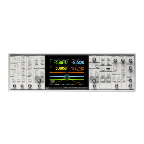
SRS Labs SR830 User manual

DSP Lock-InAmplifier
model SR830
1290 D Reamwood Avenue
Sunnyvale, CA94089 USA
Phone: (408) 744-9040 • Fax: (408) 744-9049
Copyright©1999
All Rights Reserved
Revision 1.5 • 11/99
Stanford Research Systems

GENERAL INFORMATION
Safety and Preparation for Use 1-3
Specifications 1-5
Abridged Command List 1-7
GETTING STARTED
Your First Measurements 2-1
The Basic Lock-in 2-3
X, Y, R and θ2-7
Outputs, Offsets and Expands 2-9
Storing and Recalling Setups 2-13
Aux Outputs and Inputs 2-15
SR830 BASICS
What is a Lock-in Amplifier? 3-1
What Does a Lock-in Measure? 3-3
The SR830 Functional Diagram 3-5
Reference Channel 3-7
Phase Sensitive Detectors 3-9
Time Constants and DC Gain 3-11
DC Outputs and Scaling 3-13
Dynamic Reserve 3-15
Signal Input Amplifier and Filters 3-17
Input Connections 3-19
Intrinsic (Random) Noise Sources 3-21
External Noise Sources 3-23
Noise Measurements 3-25
OPERATION
Power On/Off and Power On Tests 4-1
Reset 4-1
[Keys] 4-1
Spin Knob 4-1
Front Panel BNC Connectors 4-2
Key Click On/Off 4-2
Front Panel Display Test 4-2
Display Off Operation 4-2
Keypad Test 4-3
Standard Settings 4-4
FRONT PANEL
Signal Input and Filters 4-5
Sensitivity, Reserve, Time Constants 4-7
CH1 Display and Output 4-12
CH2 Display and Output 4-15
Reference 4-18
Auto Functions 4-21
Setup 4-23
Interface 4-24
Warning Messages 4-26
REAR PANEL
Power Entry Module 4-27
IEEE-488 Connector 4-27
RS232 Connector 4-27
Aux Inputs (A/D Inputs) 4-27
Aux Outputs (D/A Outputs) 4-27
X and Y Outputs 4-27
Signal Monitor Output 4-28
Trigger Input 4-28
TTL Sync Output 4-28
Preamp Connector 4-28
Using SRS Preamps 4-29
PROGRAMMING
GPIB Communications 5-1
RS232 Communications 5-1
Status Indicators and Queues 5-1
Command Syntax 5-1
Interface Ready and Status 5-2
GET (Group Execute Trigger) 5-2
DETAILED COMMAND LIST 5-3
Reference and Phase 5-4
Input and Filter 5-5
Gain and Time Constant 5-6
Display and Output 5-8
Aux Input and Output 5-9
Setup 5-10
Auto Functions 5-11
Data Storage 5-12
Data Transfer 5-15
Interface 5-19
Status Reporting 5-20
STATUS BYTE DEFINITIONS
Serial Poll Status Byte 5-21
Service Requests 5-22
Standard Event Status Byte 5-22
LIA Status Byte 5-23
Error Status Byte 5-23
PROGRAM EXAMPLES
Microsoft C, Nationall Instr GPIB 5-25
USING SR530 PROGRAMS 5-31
TABLE OF CONTENTS

Table of Contents
TESTING
Introduction 6-1
Preset 6-1
Serial Number 6-1
Firmware Revision 6-1
Test Record 6-1
If A Test Fails 6-1
Necessary Equipment 6-1
Front Panel Display Test 6-2
Keypad Test 6-2
PERFORMANCE TESTS
Self Tests 6-3
DC Offset 6-5
Common Mode Rejection 6-7
Amplitude Accuracy and Flatness 6-9
Amplitude Linearity 6-11
Frequency Accuracy 6-13
Phase Accuracy 6-15
Sine Output Amplitude 6-17
DC Outputs and Inputs 6-19
Input Noise 6-21
Performance Test Record 6-23
CIRCUITRY
Circuit Boards 7-1
CPU and Power Supply Board 7-3
DSP Logic Board 7-5
Analog Input Board 7-7
PARTS LISTS
DSP Logic Board 7-9
Analog Input Board 7-15
CPU and Power Supply Board 7-21
Front Panel Display Boards 7-24
Miscellaneous 7-30
SCHEMATIC DIAGRAMS
CPU and Power Supply Board
Display Board
Keypad Board
DSP Logic Board
Analog Input Board

SAFETY AND PREPARATION FOR USE
CAUTION
This instrument may be damaged if operated
with the LINE VOLTAGE SELECTOR set for the
wrong AC line voltage or if the wrong fuse is
installed.
LINE VOLTAGE SELECTION
The SR830 operates from a 100V, 120V, 220V, or
240V nominal AC power source having a line fre-
quency of 50 or 60 Hz. Before connecting the pow-
er cord to a power source, verify that the LINE
VOLTAGE SELECTOR card, located in the rear
panel fuse holder, is set so that the correct AC in-
put voltage value is visible.
Conversion to other AC input voltages requires a
change in the fuse holder voltage card position
and fuse value. Disconnect the power cord, open
the fuse holder cover door and rotate the fuse-pull
lever to remove the fuse. Remove the small print-
ed circuit board and select the operating voltage
by orienting the printed circuit board so that the
desired voltage is visible when pushed firmly into
its slot. Rotate the fuse-pull lever back into its nor-
mal position and insert the correct fuse into the
fuse holder.
LINE FUSE
Verify that the correct line fuse is installed before
connecting the line cord. For 100V/120V, use a 1
Amp fuse and for 220V/240V, use a 1/2 Amp fuse.
LINE CORD
The SR830 has a detachable, three-wire power
cord for connection to the power source and to a
protective ground. The exposed metal parts of the
instrument are connected to the outlet ground to
protect against electrical shock. Always use an
outlet which has a properly connected protective
ground.
SERVICE
Do not attempt to service or adjust this instrument
unless another person, capable of providing first
aid or resuscitation, is present.
Do not install substitute parts or perform any unau-
thorized modifications to this instrument. Contact
the factory for instructions on how to return the in-
strument for authorized service and adjustment.
WARNING
Dangerous voltages, capable of causing injury or death, are present in
this instrument. Use extreme caution whenever the instrument covers
are removed. Do not remove the covers while the unit is plugged into a
live outlet.
1-3

1-4

SR830 DSP LOCK-IN AMPLIFIER
1-5
SPECIFICATIONS
SIGNAL CHANNEL
Voltage Inputs Single-ended (A) or differential (A-B).
Current Input 106or 108Volts/Amp.
Full Scale Sensitivity 2 nV to 1 V in a 1-2-5-10 sequence (expand off).
Input Impedance Voltage: 10 MΩ+25 pF, AC or DC coupled.
Current: 1 kΩto virtual ground.
Gain Accuracy ±1% from 20°C to 30°C (notch filters off).
Input Noise 6 nV/√Hz at 1 kHz (typical).
Signal Filters 60 (50) Hz and 120(100) Hz notch filters (Q=4).
CMRR 90 dB at 100 Hz (DC Coupled).
Dynamic Reserve Greater than 100 dB (with no signal filters).
Harmonic Distortion -80 dB.
REFERENCE CHANNEL
Frequency Range 1 mHz to 102 kHz
Reference Input TTL (rising or falling edge) or Sine.
Sine input is1 MΩ, AC coupled (>1 Hz). 400 mV pk-pk minimum signal.
Phase Resolution 0.01°
Absolute Phase Error <1°
Relative Phase Error <0.01°
Orthogonality 90° ± 0.001°
Phase Noise External synthesized reference: 0.005° rms at 1 kHz, 100 ms, 12 dB/oct.
Internal reference: crystal synthesized, <0.0001° rms at 1 kHz.
Phase Drift <0.01°/°C below 10 kHz
<0.1°/°C to 100 kHz
Harmonic Detect Detect at Nxf where N<19999 and Nxf<102 kHz.
Acquisition Time (2 cycles + 5 ms) or 40 ms, whichever is greater.
DEMODULATOR
Zero Stability Digital displays have no zero drift on all dynamic reserves.
Analog outputs: <5 ppm/°C for all dynamic reserves.
Time Constants 10 µs to 30 s (reference > 200 Hz). 6, 12, 18, 24 dB/oct rolloff.
up to 30000 s (reference < 200 Hz). 6, 12, 18, 24 dB/oct rolloff.
Synchronous filtering available below 200 Hz.
Harmonic Rejection -80 dB
INTERNAL OSCILLATOR
Frequency 1 mHz to 102 kHz.
Frequency Accuracy 25 ppm + 30 µHz
Frequency Resolution 4 1/2 digits or 0.1 mHz, whichever is greater.
Distortion f<10 kHz, below -80 dBc. f>10 kHz, below -70 dBc.1 Vrms amplitude.
Output Impedance 50 Ω
Amplitude 4 mVrms to 5 Vrms (into a high impedance load) with 2 mV resolution.
(2 mVrms to 2.5 Vrms into 50Ωload).
Amplitude Accuracy 1%
Amplitude Stability 50 ppm/°C
Outputs Sine output on front panel. TTL sync output on rear panel.
When using an external reference, both outputs are phase locked to the
external reference.

SR830 DSP Lock-In Amplifier
1-6
DISPLAYS
Channel 1 4 1/2 digit LED display with 40 segment LED bar graph.
X, R, X Noise, Aux Input 1 or 2. The display can also be any of these
quantities divided by Aux Input 1 or 2.
Channel 2 4 1/2 digit LED display with 40 segment LED bar graph.
Y, θ, Y Noise, Aux Input 3 or 4. The display can also be any of these
quantities divided by Aux Input 3 or 4.
Offset X, Y and R may be offset up to ±105% of full scale.
Expand X, Y and R may be expanded by 10 or 100.
Reference 4 1/2 digit LED display.
Display and modify reference frequency or phase, sine output amplitude,
harmonic detect, offset percentage (X, Y or R), or Aux Outputs 1-4.
Data Buffer 16k points from both Channel 1 and Channel 2 display may be stored
internally. The internal data sample rate ranges from 512 Hz down to 1
point every 16 seconds. Samples can also be externally triggered. The data
buffer is accessible only over the computer interface.
INPUTS AND OUTPUTS
Channel 1 Output Output proportional to Channel 1 display, or X.
Output Voltage: ±10 V full scale. 10 mA max output current.
Channel 2 Output Output proportional to Channel 2 display, or Y.
Output Voltage: ±10 V full scale. 10 mA max output current.
X and Y Outputs Rear panel outputs of cosine (X) and sine (Y) components.
Output Voltage: ±10 V full scale. 10 mA max output current.
Aux. Outputs 4 BNC Digital to Analog outputs.
±10.5 V full scale, 1 mV resolution. 10 mA max output current.
Aux. Inputs 4 BNC Analog to Digital inputs.
Differential inputs with1 MΩinput impedance on both shield and center
conductor. ±10.5 V full scale, 1 mV resolution.
Trigger Input TTL trigger input triggers stored data samples.
Monitor Output Analog output of signal amplifiers (before the demodulator).
GENERAL
Interfaces IEEE-488 and RS232 interfaces standard.
All instrument functions can be controlled through the IEEE-488 and RS232
interfaces.
Preamp Power Power connector for SR550 and SR552 preamplifiers.
Power 40 Watts, 100/120/220/240 VAC, 50/60 Hz.
Dimensions 17"W x 5.25"H x 19.5"D
Weight 30 lbs.
Warranty One year parts and labor on materials and workmanship.

SR830 DSP Lock-In Amplifier
1-7
COMMAND LIST
VARIABLES i,j,k,l,m Integers
f Frequency (real)
x,y,z Real Numbers
s String
REFERENCE and PHASE page description
PHAS (?) {x} 5-4 Set (Query) the Phase Shift to x degrees.
FMOD (?) {i} 5-4 Set (Query) the Reference Source to External (0) or Internal (1).
FREQ (?) {f} 5-4 Set (Query) the Reference Frequency to f Hz.Set only in Internal reference mode.
RSLP (?) {i} 5-4 Set (Query) the External Reference Slope to Sine(0), TTL Rising (1), or TTL Falling (2).
HARM (?) {i} 5-4 Set (Query) the Detection Harmonic to 1 ≤i ≤19999 and i•f ≤102 kHz.
SLVL (?) {x} 5-4 Set (Query) the Sine Output Amplitude to x Vrms. 0.004 ≤x ≤5.000.
INPUT and FILTER page description
ISRC (?) {i} 5-5 Set (Query) the Input Configuration to A (0), A-B (1) , I (1 MΩ) (2) or I (100 MΩ) (3).
IGND (?) {i} 5-5 Set (Query) the Input Shield Grounding to Float (0) or Ground (1).
ICPL (?) {i} 5-5 Set (Query) the Input Coupling to AC (0) or DC (1).
ILIN (?) {i} 5-5 Set (Query) the Line Notch Filters to Out (0), Line In (1) , 2xLine In (2), or Both In (3).
GAIN and TIME CONSTANT page description
SENS (?) {i} 5-6 Set (Query) the Sensitivity to 2 nV (0) through 1 V (26) rms full scale.
RMOD (?) {i} 5-6 Set (Query) the Dynamic Reserve Mode to HighReserve (0), Normal (1), or Low Noise (2).
OFLT (?) {i} 5-6 Set (Query) the Time Constant to 10 µs (0) through 30 ks (19).
OFSL (?) {i} 5-6 Set (Query) the Low Pass Filter Slope to 6 (0), 12 (1), 18 (2) or 24 (3) dB/oct.
SYNC (?) {i} 5-7 Set (Query) the Synchronous Filter to Off (0) or On below 200 Hz (1).
DISPLAY and OUTPUT page description
DDEF (?) i {, j, k} 5-8 Set (Query) the CH1 or CH2 (i=1,2) display to XY, Rθ, XnYn, Aux 1,3 or Aux 2,4 (j=0..4)
and ratio the display to None, Aux1,3 or Aux 2,4 (k=0,1,2).
FPOP (?) i {, j} 5-8 Set (Query) the CH1 (i=1) or CH2 (i=2) Output Source to X or Y (j=1) or Display (j=0).
OEXP (?) i {, x, j} 5-8 Set (Query) the X, Y, R (i=1,2,3) Offset to x percent ( -105.00 ≤x ≤105.00)
and Expand to 1, 10 or 100 (j=0,1,2).
AOFF i 5-8 Auto Offset X, Y, R (i=1,2,3).
AUX INPUT/OUTPUT page description
OAUX ? i 5-9 Query the value of Aux Input i (1,2,3,4).
AUXV (?) i {, x} 5-9 Set (Query) voltage of Aux Output i (1,2,3,4) to x Volts. -10.500 ≤x ≤10.500.
SETUP page description
OUTX (?) {i} 5-10 Set (Query) the Output Interface to RS232 (0) or GPIB (1).
OVRM (?) {i} 5-10 Set (Query) the GPIB Overide Remote state to Off (0) or On (1).
KCLK (?) {i} 5-10 Set (Query) the Key Click to Off (0) or On (1).
ALRM (?) {i} 5-10 Set (Query) the Alarms to Off (0) or On (1).
SSET i 5-10 Save current setup to setting buffer i (1≤i≤9).
RSET i 5-10 Recall current setup from setting buffer i (1≤i≤9).
AUTO FUNCTIONS page description
AGAN 5-11 Auto Gain function. Same as pressing the [AUTO GAIN] key.
ARSV 5-11 Auto Reserve function. Same as pressing the [AUTO RESERVE] key.
APHS 5-11 Auto Phase function. Same as pressing the [AUTO PHASE] key.
AOFF i 5-11 Auto Offset X,Y or R (i=1,2,3).

SR830 DSP Lock-In Amplifier
1-8
DATA STORAGE page description
SRAT (?) {i} 5-13 Set (Query) the DataSample Rate to 62.5 mHz (0) through 512 Hz (13) or Trigger (14).
SEND (?) {i} 5-13 Set (Query) the Data Scan Mode to 1 Shot (0) or Loop (1).
TRIG 5-13 Software trigger command. Same as trigger input.
TSTR (?) {i} 5-13 Set (Query) the Trigger Starts Scan modeto No (0) or Yes (1).
STRT 5-13 Start or continue a scan.
PAUS 5-13 Pause a scan. Does not reset a paused or done scan.
REST 5-14 Reset the scan. All stored data is lost.
DATA TRANSFER page description
OUTP? i 5-15 Query the value of X (1), Y (2), R (3) or θ(4). Returns ASCII floating point value.
OUTR? i 5-15 Query the value of Display i (1,2). Returns ASCII floating point value.
SNAP?i,j{,k,l,m,n} 5-15 Query the value of 2 thru 6 paramters at once.
OAUX? i 5-16 Query the value of Aux Input i (1,2,3,4). Returns ASCII floating point value.
SPTS? 5-16 Query the number of points stored in Display buffer.
TRCA? i,j,k 5-16 Read k≥1 points starting at bin j≥0 from Display i (1,2) buffer in ASCII floating point.
TRCB? i,j,k 5-16 Read k≥1 points starting at bin j≥0 from Display i (1,2) buffer in IEEE binary floating point.
TRCL? i,j,k 5-17 Read k≥1 points starting at bin j≥0 from Display i (1,2) buffer in non-normalized binary floating
point.
FAST (?) {i} 5-17 Set (Query) Fast Data Transfer Mode On (1) or Off (0).On will transfer binary X and Y every
sample during a scan over the GPIB interface.
STRD 5-18 Start a scan after 0.5sec delay. Use with Fast Data Transfer Mode.
INTERFACE page description
❋RST 5-19 Reset the unit to its default configurations.
❋IDN? 5-19 Read the SR830 device identification string.
LOCL(?) {i} 5-19 Set (Query) the Local/Remote state to LOCAL (0), REMOTE (1), or LOCAL LOCKOUT (2).
OVRM (?) {i} 5-19 Set (Query) the GPIB Overide Remote state to Off (0) or On (1).
TRIG 5-19 Software trigger command. Same as trigger input.
STATUS page description
❋CLS 5-20 Clear all status bytes.
❋ESE (?) {i} {,j} 5-20 Set (Query) the Standard Event Status Byte Enable Register to the decimal value i (0-255).
❋ESE i,j sets bit i (0-7) to j (0 or 1). ❋ESE? queries the byte. ❋ESE?i queries only bit i.
❋ESR? {i} 5-20 Query the Standard Event Status Byte. If i is included, only bit i is queried.
❋SRE (?) {i} {,j} 5-20 Set (Query) the Serial Poll Enable Register to the decimal value i (0-255). ❋SRE i,j sets bit i (0-
7) to j (0 or 1). ❋SRE? queries the byte, ❋SRE?i queries only bit i.
❋STB? {i} 5-20 Query the Serial Poll Status Byte. If i is included, only bit i is queried.
❋PSC (?) {i} 5-20 Set (Query) the Power On Status Clear bit to Set (1) or Clear (0).
ERRE (?) {i} {,j} 5-20 Set (Query) the Error Status Enable Register to the decimal value i (0-255). ERRE i,j sets bit i
(0-7) to j (0 or 1). ERRE? queries the byte, ERRE?i queries only bit i.
ERRS? {i} 5-20 Query the Error Status Byte. If i is included, only bit i is queried.
LIAE (?) {i} {,j} 5-20 Set (Query) the LIA Status Enable Register to the decimal value i (0-255). LIAE i,j sets
bit i (0-7) to j (0 or 1). LIAE? queries the byte, LIAE?i queries only bit i.
LIAS? {i} 5-20 Query the LIA Status Byte. If i is included, only bit i is queried.

SR830 DSP Lock-In Amplifier
1-9
SERIAL POLL STATUS BYTE (5-21)
bit name usage
0 SCN No data is being acquired
1 IFC No command execution in progress
2 ERR Unmasked bit in error status byte set
3 LIA Unmasked bit in LIA status byte set
4 MAV The interface output buffer is non-empty
5 ESB Unmasked bit in standard status byte set
6 SRQ SRQ (service request) has occurred
7 Unused
STANDARD EVENT STATUS BYTE (5-22)
bit name usage
0 INP Set on input queue overflow
1 Unused
2 QRY Set on output queue overflow
3 Unused
4 EXE Set when command execution error occurs
5 CMD Set when an illegal command is received
6 URQ Set by any key press or knob rotation
7 PON Set by power-on
LIA STATUS BYTE (5-23)
bit name usage
0 RSRV/INPT Set when on RESERVE or INPUT overload
1 FILTR Set when on FILTR overload
2 OUTPT Set when on OUTPT overload
3 UNLK Set when on reference unlock
4 RANGE Set when detection freq crosses 200 Hz
5 TC Set when time constant is changed
6 TRIG Set when unit is triggered
7 Unused
ERROR STATUS BYTE (5-23)
bit name usage
0 Unused
1 Backup Error Set when battery backup fails
2 RAM Error Set when RAM Memory test finds an error
3 Unused
4 ROM Error Set when ROM Memory test finds an error
5 GPIB Error Set when GPIB binary data transfer aborts
6 DSP Error Set when DSP test finds an error
7 Math Error Set when an internal math error occurs
STATUS BYTE DEFINITIONS

SR830 DSP Lock-In Amplifier
1-10

GETTING STARTED
The sample measurements described in this section are designed to acquaint the first time user with the
SR830 DSP Lock-In Amplifier. Do not be concerned that your measurements do not exactly agree with these
exercises. The focus of these measurement exercises is to learn how to use the instrument.
It is highly recommended that the first time user step through some or all of these exercises before attempting
to perform an actual experiment.
The experimental procedures are detailed in two columns. The left column lists the actual steps in the experi-
ment. The right column is an explanation of each step.
[Keys] Front panel keys are referred to in brackets such as [Display] where
'Display' is the key label.
Knob The knob is used to adjust parameters which are displayed in the
Reference display.
2-1
YOUR FIRST MEASUREMENTS

2-2
Getting Started

2-3
THE BASIC LOCK-IN
This measurement is designed to use the internal oscillator to explore some of the basic lock-in functions.
You will need BNC cables.
Specifically, you will measure the amplitude of the Sine Out at various frequencies, sensitivities, time con-
stants and phase shifts.
1. Disconnect all cables from the lock-in. Turn
the power on while holding down the [Setup]
key. Wait until the power-on tests are
completed.
2. Connect the Sine Out on the front panel to the
A input using a BNC cable.
3. Press [Auto Phase]
4. Press [Phase]
5. Press the [+90°] key.
When the power is turned on with the [Setup] key
pressed, the lock-in returns to its standard default
settings. See the Standard Settings list in the
Operation section for a complete listing of the
settings.
The Channel 1 display shows X and Channel 2
shows Y.
The lock-in defaults to the internal oscillator refer-
ence set at 1.000 kHz. The reference mode is indi-
cated by the INTERNAL led. In this mode, the
lock-in generates a synchronous sine output at the
internal reference frequency.
The input impedance of the lock-in is 10 MΩ. The
Sine Out has an output impedance of 50Ω. Since
the Sine Output amplitude is specified into a high
impedance load, the output impedance does not
affect the amplitude.
The sine amplitude is 1.000 Vrms and the
sensitivity is 1 V(rms). Since the phase shift of the
sine output is very close to zero, Channel 1 (X)
should read close to 1.000 V and Channel 2 (Y)
should read close to 0.000 V.
Automatically adjust the reference phase shift to
eliminate any residual phase error. This should set
the value of Y to zero.
Display the reference phase shift in the Reference
display. The phase shift should be close to zero.
This adds 90° to the reference phase shift. The
value of X drops to zero and Y becomes minus the
magnitude (-1.000 V).
The Basic Lock-in

2-4
Use the knob to adjust the phase shift until Y
is zero and X is equal to the positive
amplitude.
Press [Auto Phase]
6. Press [Freq]
Use the knob to adjust the frequency to
10 kHz.
Use the knob to adjust the frequency back to
1 kHz.
7. Press [Ampl]
Use the knob to adjust the amplitude to
0.01 V.
8. Press [Auto Gain]
9. Press [Sensitivity Up] to select 50 mV full
scale.
Change the sensitivity back to 20 mV.
10. Press [Time Constant Down] to change the
time constant to 300 µs.
Press [Time Constant Up] to change the time
constant to 3 ms.
The knob is used to adjust parameters which are
shown in the Reference display, such as phase,
amplitude and frequency. The final phase value
should be close to zero again.
Use the Auto Phase function to return Y to zero
and X to the amplitude.
Show the internal oscillator frequency in the
Reference display.
The knob now adjusts the frequency. The meas-
ured signal amplitude should stay within 1% of 1 V
and the phase shift should stay close to zero (the
value of Y should stay close to zero).
The internal oscillator is crystal synthesized with
25 ppm of frequency error. The frequency can be
set with 4 1/2 digit or 0.1 mHz resolution, whichev-
er is greater.
Show the sine output amplitude in the Reference
display.
As the amplitude is changed, the measured value
of X should equal the sine output amplitude. The
sine amplitude can be set from 4 mV to 5 V rms
into high impedance (half the amplitude into a 50
Ωload).
The Auto Gain function will adjust the sensitivity so
that the measured magnitude (R) is a sizable per-
centage of full scale. Watch the sensitivity indica-
tors change.
Parameters which have many options, such as
sensitivity and time constant, are changed with up
and down keys. The sensitivity and time constant
are indicated by leds.
The values of X and Y become noisy. This is
because the 2f component of the output (at 2 kHz)
is no longer attenuated completely by the low pass
filters.
Let's leave the time constant short and change the
filter slope.
The Basic Lock-in

2-5
11. Press the [Slope/Oct] key until 6 dB/oct is
selected.
Press [Slope/Oct] again to select 12 dB/oct.
Press [Slope/Oct] twice to select 24 db/oct.
Press [Slope/Oct] again to select 6 db/oct.
12. Press [Freq]
Use the knob to adjust the frequency to
55.0 Hz.
13. Press [Sync Filter]
Parameters which have only a few values, such as
filter slope, have only a single key which cycles
through all available options. Press the corre-
sponding key until the desired option is indicated
by an led.
The X and Y outputs are somewhat noisy at this
short time constant and only 1 pole of low pass
filtering.
The outputs are less noisy with 2 poles of filtering.
With 4 poles of low pass filtering, even this short
time constant attenuates the 2f component rea-
sonably well and provides steady readings.
Let's leave the filtering short and the outputs noisy
for now.
Show the internal reference frequency on the
Reference display.
At a reference frequency of 55 Hz and a 6 db/oct,
3 ms time constant, the output is totally dominated
by the 2f component at 100 Hz.
This turns on synchronous filtering whenever the
detection frequency is below 200 Hz.
Synchronous filtering effectively removes output
components at multiples of the detection frequen-
cy. At low frequencies, this filter is a very effective
way to remove 2f without using extremely long
time constants.
The outputs are now very quiet and steady, even
though the time constant is very short. The
response time of the synchronous filter is equal to
the period of the detection frequency (18 ms in this
case).
This concludes this measurement example. You
should have a feeling for the basic operation of the
front panel. Basic lock-in parameters have been
introduced and you should be able to perform
simple measurements.
The Basic Lock-in

2-6
The Basic Lock-in

2-7
X, Y, R and θ
This measurement is designed to use the internal oscillator and an external signal source to explore some of
the display types. You will need a synthesized function generator capable of providing a 100 mVrms sine
wave at 1.000 kHz (the DS335 from SRS will suffice), BNC cables and a terminator appropriate for the gener-
ator function output.
Specifically, you will display the lock-in outputs when measuring a signal close to, but not equal to, the inter-
nal reference frequency. This setup ensures changing outputs which are more illustrative than steady outputs.
The displays will be configured to show X, Y, R and θ.
1. Disconnect all cables from the lock-in. Turn
the power on while holding down the [Setup]
key. Wait until the power-on tests are
completed.
2. Turn on the function generator, set the fre-
quency to 1.0000 kHz (exactly) and the ampli-
tude to 500 mVrms.
Connect the function output (sine wave) from
the synthesized function generator to the A
input using a BNC cable and appropriate
terminator.
3. Press [Freq]
Use the knob to change the frequency to
999.8 Hz.
When the power is turned on with the [Setup] key
pressed, the lock-in returns to its standard set-
tings. See the Standard Settings list in the
Operation section for a complete listing of the
settings.
The Channel 1 display shows X and Channel 2
shows Y.
The input impedance of the lock-in is 10 MΩ. The
generator may require a terminator. Many genera-
tors have either a 50Ωor 600Ωoutput impedance.
Use the appropriate feedthrough or T termination if
necessary. In general, not using a terminator
means that the function output amplitude will not
agree with the generator setting.
The lock-in defaults to the internal oscillator refer-
ence set at 1.000 kHz. The reference mode is indi-
cated by the INTERNAL led. In this mode, the
internal oscillator sets the detection frequency.
The internal oscillator is crystal synthesized so
that the actual reference frequency should be very
close to the actual generator frequency. The X and
Y displays should read values which change very
slowly. The lock-in and the generator are not
phase locked but they are at the same frequency
with some slowly changing phase.
Show the internal oscillator frequency on the
Reference display.
By setting the lock-in reference 0.2 Hz away from
the signal frequency, the X and Y outputs are
0.2 Hz sine waves (frequency difference between
reference and signal). The X and Y output displays
X, Y, R and θ

2-8
X, Y, R and θ
should now oscillate at about 0.2 Hz (the accuracy
is determined by the crystals of the generator and
the lock-in).
The default Channel 1 display is X. Change the
display to show R. R is phase independent so it
shows a steady value (close to 0.500 V).
The default Channel 2 display is Y. Change the
display to show θ. The phase between the refer-
ence and the signal changes by 360° approximate-
ly every 5 sec (0.2 Hz difference frequency).
The bar graph in this case is scaled to ±180°. The
bar graph should be a linear phase ramp at
0.2 Hz.
Show the internal oscillator frequency.
As the internal reference frequency gets closer to
the signal frequency, the phase rotation gets
slower and slower. If the frequencies are
EXACTLY equal, then the phase is constant.
By using the signal generator as the external refer-
ence, the lock-in will phase lock its internal oscilla-
tor to the signal frequency and the phase will be a
constant.
Select external reference mode. The lock-in will
phase lock to the signal at the Reference Input.
With a TTL reference signal, the slope needs to be
set to either rising or falling edge.
The phase is now constant. The actual phase
depends upon the phase difference between the
function output and the sync output from the
generator.
The external reference frequency (as measured by
the lock-in) is displayed on the Reference display.
The UNLOCK indicator should be OFF (success-
fully locked to the external reference).
The displays may be stored in the internal data
buffers at a programmable sampling rate. This
allows storage of 16000 points of both displays.
4. Press [Channel 1 Display] to select R.
5. Press [Channel 2 Display] to select θ.
6. Press [Freq]
Use the knob to adjust the frequency slowly to
try to stop the rotation of the phase.
7. Use a BNC cable to connect the TTL SYNC
output from the generator to the Reference
Input of the lock-in.
Press [Source] to turn the INTERNAL led off.
Press [Trig] to select POS EDGE.

2-9
OUTPUTS, OFFSETS and EXPANDS
This measurement is designed to use the internal oscillator to explore some of the basic lock-in outputs. You
will need BNC cables and a digital voltmeter (DVM).
Specifically, you will measure the amplitude of the Sine Out and provide analog outputs proportional to the
measurement. The effect of offsets and expands on the displayed values and the analog outputs will be
explored.
1. Disconnect all cables from the lock-in. Turn
the power on while holding down the [Setup]
key. Wait until the power-on tests are
completed.
2. Connect the Sine Out on the front panel to the
A input using a BNC cable.
3. Connect the CH1 OUTPUT on the front panel
to the DVM. Set the DVM to read DC Volts.
4. Press [Ampl]
Use the knob to adjust the sine amplitude to
0.5 V.
When the power is turned on with the [Setup] key
pressed, the lock-in returns to its standard set-
tings. See the Standard Settings list in the
Operation section for a complete listing of the
settings.
The Channel 1 display shows X and Channel 2
shows Y.
The lock-in defaults to the internal oscillator refer-
ence set at 1.000 kHz. The reference mode is indi-
cated by the INTERNAL led. In this mode, the
lock-in generates a synchronous sine output at the
internal reference frequency.
The input impedance of the lock-in is 10 MΩ. The
Sine Out has an output impedance of 50Ω. Since
the Sine Output amplitude is specified into a high
impedance load, the output impedance does not
affect the amplitude.
The sine amplitude is 1.000 Vrms and the
sensitivity is 1 V(rms). Since the phase shift of the
sine output is very close to zero, Channel 1 (X)
should read close to 1.000 V and Channel 2 (Y)
should read close to 0.000 V.
The CH1 output defaults to X. The output voltage
is simply (X/Sensitivity - Offset)xExpandx10V. In
this case, X = 1.000 V, the sensitivity = 1 V, the
offset is zero percent and the expand is 1. The
output should thus be 10 V or 100% of full scale.
Display the sine output amplitude.
Set the amplitude to 0.5 V. The Channel 1 display
should show X=0.5 V and the CH1 output voltage
should be 5 V on the DVM (1/2 of full scale).
Outputs, Offsets and Expands
Table of contents
Other SRS Labs Amplifier manuals

SRS Labs
SRS Labs SR124 User manual

SRS Labs
SRS Labs SR446 User manual

SRS Labs
SRS Labs SR445A User manual

SRS Labs
SRS Labs SR560 Guide

SRS Labs
SRS Labs SR530 Owner's manual

SRS Labs
SRS Labs SR550 User manual

SRS Labs
SRS Labs SR850 User manual

SRS Labs
SRS Labs SR555 User manual

SRS Labs
SRS Labs FS710 User manual

SRS Labs
SRS Labs SR865A User manual