SRS Labs CMC24-DIGI User manual

( 1 / 8)
Instruction Manual
Models:
version 3.1 since 3 February 2020
ATTENTION!
This instruction manual contains important information about the installation and the use of
the equipment. Please read and follow these instructions carefully.
Always ensure that the power to the equipment is disconnected before opening the
equipment or commencing any maintenance wor .
CMCXX-DIGI_en_manual_M011.doc
igital Remote
for Hoist Controller
CMC24- IGI, CMC16- IGI
CMC12- IGI, CMC8- IGI,

( 2 / 8)
Safety information
IMPORTANT INSTRUCTIONS
All safety and operating instructions should be read before the equipment is installed or operated.
IMPORTANT SAFETY INFORMATION
The following general safety precautions have to be observed during all phases of operation, service,
and the repair of this equipment. Failure to comply with these precautions or with specific warnings
in this manual violates safety standards of design, manufacture, and the intended use of this
equipment.
Do not operate in an explosive atmosphere!
Do not operate this equipment in the presence of flammable gases or fumes. Operation of any
electrical instrument in such an environment constitutes a definite safety hazard.
ater, moisture, heat and humidity
Do not operate this equipment near water or in areas with wet floors or in high humidity atmosphere,
where condensation forms on the equipment. It should never be placed near or over a heat register
or other source of heated air and it should not be installed or operated without proper ventilation.

( 3 / 8)
Operation
The CMCxx-DIGI is manufactured from 1 to 48 channels and it suits as directional remote for digital
controllers. The CMCxx-DIGI Motors/Hoists connected to the CMC-LVseries, GMDseries and
AHDseries controller can be activated individually or simultaneously using the GO button located on
the CMCxx-DIGI cable or wireless controller /WMC-DIGI/. The selection of the hoists to be controlled
should be done by the WMC or CMC switches. Units can be lin ed together to create bigger systems.
How to start
•Connect a 5-pin NC5MXX plug to the remote input of the CMCxx-D unit.
•Chec if the emergency STOP button on both MC and WMC devices is released. If not, this
state will be indicated by the status B LED blin ing in red color. Chec STOP buttons on all
connected controllers. Rotate them cloc wise to release.
•There is an additional emergency input for the connection of load cell input located on the
rear side of the controller. If the reason for an emergency STOP is other than the press of
the emergency STOP button, the status B LED is in orange color. To reset it, press and
release the emergency STOP button. In normal operation, the status B LED is in green color.
•Move the lever on CMCxx-DIGI or WMCxx-DIGI corresponding to each motor to the desired
position. According to the position of lever, hoists act as follows:
oUP - Lever in upper position
oSTAY – Lever in middle position
oDOWN - Lever in lower position
•Pushing the GO button will activate the motors and move them simultaneously.
•Releasing the GO button will stop the movement of the motors simultaneously.
•When the device is not in use, it is highly recommended to turn it OFF using the ey located
on the front panel.
To Move a Single Motor:
•Set the UP/DOWN toggle switch for desired motor to the desired direction. The associated
LED will illuminate green for UP and red for DOWN direction.
•Hold the GO button until the motor(s) is/are moved to the desired height, then release.
To Move Several Motors:
•Set the UP/DOWN toggle switches for each motor to the desired direction. The associated
LEDs will illuminate green for UP and red for DOWN direction.
•Hold the GO button until the motors are moved to the desired height, then release.

( 4 / 8)
CMC-DIGITAL series controller
CMC-DIGITALseries controller allows controlling of the RMCseries or GMDseries and GMC-LVseries
via digital 5-pin cable connector. During standard operation, the full line cable must be equipped with
Neutri 5-pin connectors. Maximum cable length is 100m. The data connection is performed via
RS485 communication line.
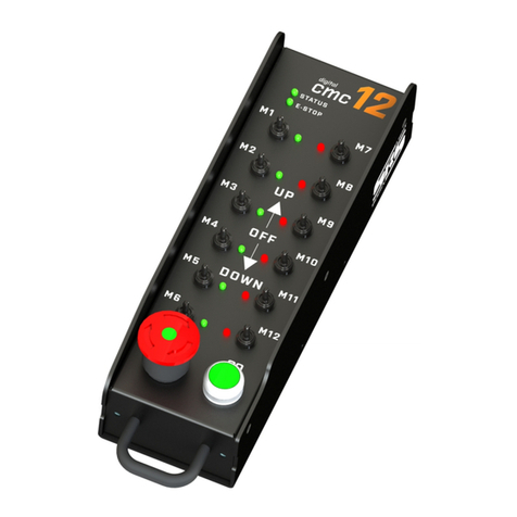
CMC 6-DIGI

( 5 / 8)
CMC 2-DIGI / CMC8-DIGI / CMC4-DIGI
STOP:
This switch protects the operation of the base unit from undesired operation and its press turns the
Controller to an inactive state. STOP is a red color button. Once the STOP button has been pressed,
system is loc ed in an inactive position and the button must be rotated cloc wise to be released to
continue operation.
GO:
This green button turns the selected channels of Hoist Control system ON when it is active. Once
the GO button has been depressed, the energizing of the hoists is turned off.
DIRECTION SWITCHES:
They allow changing the direction of movement for each motor/hoist separately or in groups. The
LED located close to the switch indicates the direction of movement.
DIRECTION SWITCH LED
•Green UP
•Red DOWN
•No light stays in position
STATUS LED

( 6 / 8)
•Green Device ready for action
•Red Indicates that the GO button is active
•Orange Indicates the activity of direction switch, LED blin s in movement
E-STOP LED
•Green E-STOP system OK
•Orange Indicates that the system needs to be reset
•Red E-STOP is active somewhere in the system
•RED blin ing E-STOP button is pressed on the device
Remote connector
Neutri NC5-FDL
Pin Function note
1 Data CMN Data Common
2 Data - Data Minus
3 Data+ Data Plus
4 DC
Power supply for CMC
DC12-36V
5 DC2
Power supply for CMC
DC12-36V
Housing + Dimensions
3mm lightweight aluminum box
CMC12-DIGI: 107 x 330 x 105 mm
CMC8-DIGI: 107 x 260 x 105 mm
CMC4-DIGI: 107 x 190 x 105 mm
Warranty
CMC-DIGITALseries hoist controller is covered by a 2-year manufacturer’s warranty. For extended
warranty conditions, please contact the manufacturer at sales@srs-group.com.
Warranty covers the original factory installed components of the controller and their correct
functioning.
Warranty voids if any part or replacement components is installed or modified without authorization
from the manufacturer and/or the internal circuit is tampered or modified and/or the controller is
operated outside normal use conditions and if the electrical power supply is not conform or there is
connection error or mechanical damage of controller, including overload and improper use.
We, as a manufacturer, always help you to repair your unit.

( 7 / 8)

( 8 / 8)
Copyright 2017 SRS Group, s.r.o. | Specifications subject to change without notice.
Document: CMCXX-DIGI_en_manual_M011.doc | Version 3.1 | Actual as of: 3 February 2020
SRS Group s.r.o.
Rybnicna 38/B | 831 07 Bratislava | Slova ia
Phone: +421 2 32 661 800
Email: sales@srs-group.com | www.srs-group.com
This manual suits for next models
3
Table of contents
Other SRS Labs Remote Control manuals
