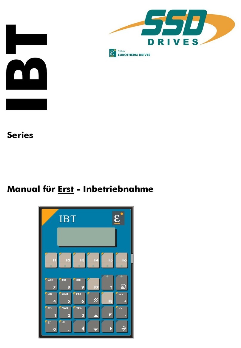
SSD Drives IBT Series Technical specifications

Series

Produkt-Beschreibung Typ: IBT V03.25EH99 (UL: 9.5.1) 2Product Description Model: IBT V03.25EH99 (UL: 9.5.1)
Intelligentes Bedien-Terminal
Intelligent Operator Terminal
Typ / Model :IBT
Produkt-Beschreibung
Product Description

Produkt-Beschreibung Typ: IBT V03.25EH99 (UL: 9.5.1) 3Product Description Model: IBT V03.25EH99 (UL: 9.5.1)
Weitere Unterlagen,Further descriptions,
die im Zusammenhang mit that relate to this document.
diesem Dokument stehen.
635 - Produkt-Handbuch
UL: 7.1.5.6
635 - Product manual
631 - Produkt-Handbuch
UL: 7.1.8.2
631 - Product manual
637 - Produkt-Handbuch
UL: 7.2.8.3
637 - Product manual
CAN - Produkt-Handbuch
UL: 7.5.3.2
CAN - Product manual
IBT - Erstinbetriebnahme
UL: 9.5.2
IBT - Getting started
IBT - Produkt-Handbuch
UL: 9.5.3
IBT - Product manual
ãEUROTHERM Antriebstechnik GmbH.
Alle Rechte vorbehalten. Kein Teil der Beschreibung darf
in irgendeiner Form, ohne Zustimmung der Gesellschaft
vervielfältigt oder weiter verarbeitet werden.
Änderungen sind ohne vorherige Ankündigung
vorbehalten.
EUROTHERM hat für seine Produkte teilweise Waren-
zeichenschutz und Gebrauchsmusterschutz eintragen
lassen. Aus dem Überlassen der Beschreibungen darf
nicht angenommen werden, daß damit eine Übertragung
von irgendwelchen Rechten stattfindet.
Hergestellt in Deutschland, 1998
ãEUROTHERM Drives Limited.
All rights reserved. No portion of this description may
be produced or processed in any form without the
consent of the company.
Changes are subject to change without notice.
EUROTHERM has registered in part trademark
protection and legal protection of designs. The handing
over of the descriptions may not be construed as the
transfer of any rights.
Made in Germany, 1998

Produkt-Beschreibung Typ: IBT V03.25EH99 (UL: 9.5.1) 4Product Description Model: IBT V03.25EH99 (UL: 9.5.1)
INHALTSVERZEICHNIS CONTENTS
Seite/Page
Das Wichtigste zuerst.................................The most important thing first...................... 5
1 Allgemeines .......................................General........................................................... 6
1.1 Beschreibung................................................ Description ..................................................................6
1.2 Anwendung mit Geräten der 630 Serie........ Application with devices of series 630 ........................7
1.3 Typenschlüssel ............................................. Key to the models ........................................................8
2 Tastaturbelegung..............................Keyboard layout............................................. 9
2.1 Frontansicht.................................................. Front view ...................................................................9
2.2 Einschubstreifen........................................... Slide-in strip ..............................................................10
2.3 Terminal-Rückseite...................................... Rear of terminal ........................................................11
2.4 Terminal-Seitenansicht ................................ Terminal side view ....................................................12
3 Tastenerklärung ...............................Keyboard layout........................................... 13
3.1 Tastatur allgemein........................................ Keyboard general......................................................13
3.2 Funktionstasten ............................................ Function keys.............................................................13
3.3 Steuertasten .................................................. Control keys...............................................................14
3.4 Sondertasten ................................................. Special keys ...............................................................15
3.5 Editiertasten.................................................. Editing keys ...............................................................15
3.6 Display ......................................................... Display ......................................................................16
3.6.1 Kontrasteinstellung.............................................Contrast setting.................................................................17
3.6.2 Grundkontrasteinstellung....................................Basic contrast setting........................................................17
4 Abmessungen ....................................Dimensions .................................................. 18
4.1 Frontplatte mit Hinterfront- Montage .......... Front panel with rear mounting from the front.........18
4.2 Frontausschnitt bei Hinterfront-Montage..... Front cutout with rear mounting from the front........19
4.3 Seitenansicht, Einbautiefe............................ Side view, installation depth .....................................20
5 Anschlußbelegung ............................Connector pin assignment .......................... 21
5.1 Schirmung .................................................... Shielding....................................................................21
5.2 Schnittstellen................................................ Interfaces...................................................................21
5.2.1 Steckerbelegung X1 Versorgungsspannung .......Connector pin assignment X1 supply voltage...................22
5.3 Busschnittstelle CAN im.............................. Bus interface in the
Bedien-Terminal .......................................... operator terminal ......................................................23
5.3.1 Pin-Belegung X2.1 CAN-Schnittstelle ...............Pin assignment X2.1 CAN interface .................................23
5.3.2 Pin-Belegung X2.2 CAN-Schnittstelle ...............Pin assignment X2.2 CAN interface .................................23
5.4 Serielle Schnittstelle im ............................... Serial interface in the
Bedien-Terminal .......................................... operator terminal ......................................................24
5.4.1 Pin-Belegung X3 RS232-Schnittstelle................Pin assignment X3 RS232 interface..................................24
6 Technische Daten..............................Technical data ............................................. 25
7 Hinweise ............................................Hints............................................................. 27
7.1 Batterie ......................................................... Battery .......................................................................27
7.2 Sicherung...................................................... Fuses..........................................................................27
8 Änderungsliste ..................................Modification Record.................................... 28

Produkt-Beschreibung Typ: IBT V03.25EH99 (UL: 9.5.1) 5Product Description Model: IBT V03.25EH99 (UL: 9.5.1)
Das Wichtigste zuerst The most important thing first
Wir bedanken uns für das Vertrauen,
das Sie unserem Produkt entgegenbringen.
We thank you for the trust that you have
shown in our product.
Die vorliegende Betriebsanleitung dient der
Übersicht von technischen Daten und
Eigenschaften.
Bitte lesen Sie vor Einsatz des Produktes
diese Bedienungsanleitung.
Bei Rückfragen wenden Sie sich bitte an
Ihren nächsten Eurotherm-Ansprechpartner.
The operating instructions presented here
serves as an overview of the technical data
and features.
Please read the operating instructions before
putting the product to use.
If you have any questions, please contact your
nearest Eurotherm representative
Der nicht sachgemäße Einsatz des Produktes
im Zusammenhang mit lebensgefährlicher
Spannung kann zu Verletzungen führen.
Des weiteren können dadurch
Beschädigungen an Motoren oder Produkten
auftreten. Berücksichtigen Sie deshalb bitte
unbedingt unsere Sicherheitshinweise.
Thema: Sicherheitshinweise
Wir gehen davon aus, daß Sie als Fachmann
mit den einschlägigen Sicherheitsregeln,
insbesondere nach VDE 0100, VDE 0113,
VDE 0160, EN 50178 den Unfallverhütungs-
vorschriften der Berufsgenossenschaft und den
DIN-Vorschriften vertraut sind und mit ihnen
umgehen können.
Des weiteren sind die CE - Bestimmungen
einzuhalten und sicherzustellen.
Je nach Einsatzart sind weitere nationale
Normen, wie z. B. UL, DIN zu beachten.
Wenn der Einsatz unserer Produkte im
Zusammenhang mit Komponenten anderer
Hersteller erfolgt, sind auch deren
Betriebsanleitungen unbedingt zu beachten.
Improper application of the product in
connection with dangerous voltage, can lead
to injuries.
In addition, damage can also occur to motors
or other products.
Therefore please observe strictly our safety
precautions.
Topic: Safety precautions
We assume that as an expert, you are familiar
with the relevant safety regulations, especially
in accordance with VDE 0100, VDE 0113,
VDE 0160, EN 50178, the accident prevention
regulations of the employers liability insurance
company and the DIN regulations and that you
can use and apply them.
Also the CE - regulations are to be observed
and guaranteed.
Depending on the kind of application, additional
norms e.g. UL, DIN are to be observed.
If our products are employed in connection with
components from other manufacturers, their
operating instructions are also to be strictly
observed.

Produkt-Beschreibung Typ: IBT V03.25EH99 (UL: 9.5.1) 6Product Description Model: IBT V03.25EH99 (UL: 9.5.1)
1 Allgemeines General
1.1 Beschreibung Description
Das Intelligente Bedien-Terminal IBT verein-
facht die Ein- und Ausgabe von Prozeßgrößen
für den Anwender. Eine komfortable
Bedienung wird durch die Integration des
TesiMod-Bedienkonzeptes erreicht.
The intelligent operator terminal IBT
facilitates the input and output of process
variables for the user. Convenient operating
is achieved through the integration of the
TesiMod operating concept.
Das IBT verfügt trotz geringer Abmessungen
über alle erforderlichen Bedienelemente eines
vollwertigen Terminals. Eine hinterleuchtete
kontrastreiche LCD-Anzeige sorgt für gute
Ablesbarkeit der Texte und Prozeßvariablen.
Der Kontrast der Anzeige wird über den
gesamten Temperaturbereich kompensiert.
Despite its small dimensions, the IBT has all
the operating elements required of a full-
fledged terminal. A rear-illuminated high-
contrast LCD display provides for good
readability of the texts and process variables.
The contrast of the display is compensated
over the whole temperature range.
Die eingebaute Lithium-Batterie erhält die
Rezepturdaten, die Inhalte eingegangener
Meldungen und versorgt die Echtzeituhr. Die
Batteriekapazität wird vom System ständig
überwacht. Beim Unterschreiten eines
Schwellwertes wird eine Klartext-System-
Fehlermeldung erzeugt. Die Aufteilung der
Datenspeicher für Rezepturen und Meldungen
kann vom Anwender projektiert werden. Im
Speicher können ca. 3000 Meldungen chrono-
logisch gespeichert werden.
The built-in lithium battery maintains the
structure data, the contents of the received
messages and suppplies the real time clock.
The batery capacity is constantly monitored
by the system. When it falls below a threshold
value, a plaintext system error message is
produced. The division of the data memory for
structures and messages can be configured by
the user. About 3000 messages can be stored
chronological in the memory.
Die Kommunikation mit dem IBT erfolgt über
zwei serielle Schnittstellen. Die Modularität
der Hard- und Software erlaubt die schnelle
Anpassung an unterschiedliche Schnittstellen-
Standards und Übertragungsprotokolle.
Communication with the IBT is done over two
serial interfaces. The modularity of the hard-
and software allows quick adaptation to the
different interface standards and transmission
protocols.
TesiMod - Das Bedienkonzept mit System TesiMod - The systematic operating system
TesiMod-Bedienterminals entlasten im
Standard-Mode die Steuerung vollständig von
Bedienaufgaben. Durch hierarchische Menü-
strukturen mit Direktanwahltasten für häufig
benötigte Masken, werden übersichtliche und
leistungsfähige Mensch-Maschine-Schnitt-
stellen (MMI) aufgebaut. Alle Funktionstasten
können menüspezifisch definiert werden (Soft-
keytechnik). Zur Gestaltung der Masken
stehen eine Vielfalt von verschiedenen Text-
und Variablenformaten zur Verfügung.
TesiMode operating terminals in standard
mode relieve the controller completely of
operating tasks. Through hierarchical menu
structures with direct dial keys for frequently
needed masks, clear and efficient man-to-
machine interfaces (MMI) are established.
All function keys can be defined specific to the
menu (soft key technology). For creating the
masks a variety of different text and variable
formats are available.

Produkt-Beschreibung Typ: IBT V03.25EH99 (UL: 9.5.1) 7Product Description Model: IBT V03.25EH99 (UL: 9.5.1)
Beschreibung Description
TesiMod - Das Bedienkonzept mit System TesiMod - The systematic operating system
Funktionstasten lassen sich für direkte Bedien-
aufgaben in der Steuerung programmieren. Der
Betriebszustand der integrierten Leuchtdiode
signalisiert die ausgelöste Aktivität.
Ein kontextsensitives Hilfssystem unterstützt
den Anlagenbediener in optimaler Weise, ohne
lästiges blättern in Handbüchern.
Function keys can be programmed for direct
operating tasks in the controller. The
operating state of the integrated LED signals
the initiated activity. A context sensitive
HELP system supports the installation
operator optimally without the nuisance of
paging through manuals.
Im Standard-Mode wird die Anwendungs-
beschreibung, bestehend aus den Masken,
Variablen und der Bedienstruktur mit Hilfe
eines komfortablen Programms am PC erstellt.
In standard mode the application description
consisting of masks, variables and the
operating structure is created on a PC with
the help of a convenient program.
1.2 Anwendung mit Geräten Application with devices
der 630 Serie of series 630
In Verbindung mit den Geräten der 630 Serie
sind mit dem IBT über die CAN- Schnittstelle
folgende Funktionen realisierbar.
In connection with the devices of the 630
series the following functions are realizable
with the IBT via the CAN- interface.
•Lese- und Schreibzugriff vom IBT auf die
Variablen und Merker des Reglers.
•Lesezugriff vom IBT auf die Istpositionen
des Reglers.(Resolverposition, X40-
Inkrementaleingang, Absolutwertgeber)
•Ansteuerung der Masken, Meldungen und
LED-Anzeige des IBT durch den Regler
über BIAS-Befehle.
•Datensatzverwaltung zwischen IBT und
Regler.
•Reading and write access of the IBT onto
the variables and flags of the drive.
•Read access of the IBT to the actual
positions of the drive.(resolver position,
X40 inkremental input, absolute encoder)
•Controlling of the masks, messages and
LED display of the IBT by the drive via
BIAS commands.
•Data set management between IBT and the
drive.

Produkt-Beschreibung Typ: IBT V03.25EH99 (UL: 9.5.1) 8Product Description Model: IBT V03.25EH99 (UL: 9.5.1)
1.3 Typenschlüssel Key to the models
Kennung
Marking a b c
Typ:
Model: IBT X XXX
Beschreibung Kennung
Marking Description
IBT = Intelligentes Bedien-Terminal aIBT = Intelligent Operator Terminal
T= für Tafeleinbau bT= for panel mounting
zusätzliche Schnittstellen-
Ausführung:
CAN =CAN
cadditional interface
model:
CAN =CAN

Produkt-Beschreibung Typ: IBT V03.25EH99 (UL: 9.5.1) 9Product Description Model: IBT V03.25EH99 (UL: 9.5.1)
2 Tastaturbelegung Keyboard layout
2.1 Frontansicht Front view
1 Nummerische Tasten
2 Cursor-Tasten
3 Cursor-home
4 Datenübernahme-Taste
(Enter)
5 Vorzeichen
6 Löschen-Taste (Clear)
7 Hilfetaste
8 Datenfreigabe-Taste
9 Datenfreigabe-LED
10 Hilfetasten LED
11 Funktionstasten LED
12 Funktionstasten F1...F6
13 Filterscheibe, Display-
ausschnitt
14 Firmen-Logo
15 Massive Alu-Frontplatte
16 Polyester-Frontfolie
17 Gerätebezeichnung
1 numbered keys 0 to 9
2 cursor keys
3 cursos home
4 data takeover key
(enter)
5sign
6 delete key (clear)
7 help key
8 data entering key
9 data entering LED
10 help key LED
11 function key LED
12 function keys F1 to F6
13 filter, display cutout
14 company logo
15 massive aluminium
front panel
16 polyester front foil
17 device designation

Produkt-Beschreibung Typ: IBT V03.25EH99 (UL: 9.5.1) 10 Product Description Model: IBT V03.25EH99 (UL: 9.5.1)
2.2 Einschubstreifen Slide-in strip
Der Einschubstreifen kann im eingebauten
Zustand gewechselt werden. Durch den Ein-
schub des Streifens von der Rückseite der
Frontplatte wird die angegebene Dichtigkeit
des Gerätes nicht beeinflußt.
Im Lieferumfang ist ein Einschubstreifen, be-
schriftet mit F1...F6 und ein unbeschrifteter
Streifen enthalten.
The slide-in strip can be changed in the built-
in state. When the strip is pushed in from the
rear of the front plate the specified sealing
capacity of the device is not affected.
Included in the delivery is a slide-in strip
lettered with F1 to F6 and a non-lettered
strip.
Je nach Stückzahl eignen sich verschiedene
Verfahren zur individuellen Beschriftung.
Prototypen: Beschriftung mit wasserfestem
Stift
Kleinserien: Kopierfolie mit Laserdruck
Großserien: kundenspezifisch, bedruckter
Einschubstreifen
Depending on the number of items, different
processes are appropriate for individual
lettering.
Prototype: lettering with indelible pen
Small series: copy foil with laser printing
Large series: specific to the customer,
printed slide-in strips
Lage der Einschubstreifen im IBT Position of the slide-in strip in the IBT
Einschubstreifen unbeschriftet Non-lettered slide-in strip
Einschubstreifen beschriftet, Standard Lettered slide-in strip, standard

Produkt-Beschreibung Typ: IBT V03.25EH99 (UL: 9.5.1) 11 Product Description Model: IBT V03.25EH99 (UL: 9.5.1)
2.3 Terminal-Rückseite Rear of terminal
Sicherung
Fuse
Steckerbelegung X2.2
Erdschraube
Ground scre
w
Stecker X1, Anschluß der
Versorgungsspannung
Plug X1, supply voltage
Connector pin assignment X2.2
X1
X3
Sicherung nach Öffnen
des Gehäuses zugänglich
F 0,63A M
Vor Öffnen des Gehäuses
ist das Gerät von der
Betriebsspannung zu trennen.
RS232c / V.24
1 nc
2 RD
3 TD
4 DTR
5 GND
6 nc
7 RTS
8 CTS
9 nc
X2.1 X2.2
1 nc
2 CAN_L
3 CAN_GND
4 nc
5 nc
6 CAN_GND
7 CAN_H
8 nc
9 nc
1 nc
2 CAN_L
3 CAN_GND
4 nc
5 nc
6 CAN_GND
7 CAN_H
8 nc
9 nc
CAN-BUS
Steckerbelegung X2.1
Connector pin assignment X2.1
Steckerbelegung X1
Connector pin assignment X1
Steckerbelegung X3
Connector pin assignment X3
Stecker X3, Anschluß RS232
Plug X3, RS232 connection
Stecker X2.1, Anschluß CAN-Bus
Plug X2.1, CAN bus connection
Stecker X2.2, Anschluß CAN-Bus
Plug X2.2, CAN bus connection
Gehäuseschrauben
Enclosure screws
connection

Produkt-Beschreibung Typ: IBT V03.25EH99 (UL: 9.5.1) 12 Product Description Model: IBT V03.25EH99 (UL: 9.5.1)
2.4 Terminal-Seitenansicht Terminal side view
User-Mode-Switch User-Mode-Switch
Ein Aus Schalter / Switch On Off
Standard-Mode Transparent-Mode S1 Standard-Mode Transparent-Mode
frei frei S2 free free
Kommunikation
mit der SPS
S3 communication
with the PLC
Erase Flash
bedingungslos
Flash-Daten
erhalten
S4 erase flash
unconditionally
keep flash data
DIP-switch User-Mode-Switch
DIP-Schalter User-Mode-Switch
1234

Produkt-Beschreibung Typ: IBT V03.25EH99 (UL: 9.5.1) 13 Product Description Model: IBT V03.25EH99 (UL: 9.5.1)
3 Tastenerklärung Keyboard layout
3.1 Tastatur allgemein Keyboard general
Das IBT verfügt trotz geringer Abmessungen
über alle wichtigen Tastenfunktionen ohne
Doppelbelegung.
Die Tastatur besteht aus einer Folientastatur
in Leitsilbertechnologie mit vergoldetem
Schnappfederkontakt aufgebaut.
Der Betätigungsweg beträgt ca. 0,6mm, die
Tastenfläche 15 x 15mm. Die Tastenelemente
sitzen unter einer geprägten, gegen Umwelt-
einflüsse resistenten Polyesterfolie.
Die bei verschiedenen Tasten erforderliche
LED sitzt direkt unter oder über dem zuge-
hörigen Tastenelement. Die LED leuchtet in
einer grünen Farbe.
Im Standard-Mode ist die Wirkung der Tasten
von der Anwenderbeschreibung abhängig.
Despite its small dimensions the IBT has
all the important key functions without
doubling up.
The keyboard consists of a plastic foil
keyboard constructed in silver conductor
technology with gold-covered snap spring
contact. The movement path is about 0.6 mm,
the key surface is 15 by 15 mm. The key
elements are under a printed polyester foil
resistent to environmental influences.
The LED required with different keys is
directly below or above the assigned key
element. The LED lights up in a greren color
In the standard mode the effect of the keys
depends on how the user describes them.
3.2 Funktionstasten Function keys
Erklärung Bezeichnung Taste / Key Designation Explanation
Frei belegbare Tastenfunktion
im Standard-Mode mit Soft-
key-Funktionalität, wahlweise
als Direkttaste zur Menü-
steuerung oder zur Auslösung
einer Funktion in der
Steuerung
F1..F6
mit integrierten
LED’s
F1 to F6
with integrated
LEDs
Freely-allocatable key
function in standard mode
with soft key operation,
optionally als direct key for
menu control or for triggering
a function in the controller.

Produkt-Beschreibung Typ: IBT V03.25EH99 (UL: 9.5.1) 14 Product Description Model: IBT V03.25EH99 (UL: 9.5.1)
3.3 Steuertasten Control keys
Erklärung Bezeichnung Taste / Key Designation Explanation
kann zur Direktanwahl be-
nachbarter Knoten- und E/A-
Masken programmiert werden.
Positioniert im Editor die
Schreibmarke (Cursor) nach
links.
Cursor links Cursor left can be programmed for direct
selection of neighboring nodes
and I/O masks. Positions the
cursos to the left in the editor.
kann zur Direktanwahl be-
nachbarter Knoten- und E/A-
Masken programmiert werden.
Positioniert im Editor die
Schreibmarke (Cursor) nach
rechts.
Cursor rechts Cursor right can be programmed for direct
selection of neighboring nodes
and I/O masks. Positions the
cursor in the editor upwards.
kann zur Direktanwahl be-
nachbarter E/A-Masken pro-
grammiert werden.
Positioniert im Editor die
Schreibmarke (Cursor) nach
oben.
Cursor auf Cursor up can be programmed for direct
selection of neighboring I/O
masks. Positions the cursor in
the editor upwards.
kann zur Direktanwahl be-
nachbarter E/A-Masken pro-
grammiert werden.
Positioniert im Editor die
Schreibmarke (Cursor) nach
unten.
Cursor ab Cursor down can be programmed for direct
selection of neighboring I/O
masks. Positions the cursor in
the editor downwards.
kann zur Direktanwahl über-
geordneter Knoten- und E/A-
Masken programmiert werden.
Positioniert im Editor die
Schreibmarke an die Position
der ersten Eingabe-Variablen.
Cursor home Cursor home can be programmed for direct
selection of superordinate
nodes and I/O masks.
Positions the cursor in the
editor to the position of the
first entry variable.

Produkt-Beschreibung Typ: IBT V03.25EH99 (UL: 9.5.1) 15 Product Description Model: IBT V03.25EH99 (UL: 9.5.1)
3.4 Sondertasten Special keys
Erklärung Bezeichnung Taste / Key Designation Explanation
gibt immer den aktuellen
Hilfetext (Online Hilfe) aus.
Das Blinken der LED signali-
siert anstehende
Fehlermeldungen. Die
Ausgabe der Fehler- oder
Systemmeldung erfolgt immer
im Klartext.
Hilfe Help always displays the current
help text (online help). The
blinking of the LED signals
queued error messages. Error
or system messages are
always issued in plaintext.
wechselt aus dem Menü in den
Editor. Die integrierte LED
leuchtet im Editierbetrieb.
Beim Betätigen im Editierbe-
trieb wird dieser wieder ver-
lassen.
Datenfreigabe Enter data changes from the menu to the
editor. The integrated LED
lights up when the editor is in
operation. Leaves the editor
when pushed during editor
operation.
dient zum Abschluß der
Dateneingabe. Verzweigt beim
Betätigen während der
Startup-Maske in die Setup-
Maske.
Enter Enter used to complete data entry.
Whem pushed during the
startup mask, branches to the
setup mask.
löscht im Editor das Zeichen
unter der Schreibmarke. Ent-
fernt die angewählten
Meldungen aus dem Daten-
speicher.
Löschen Delete deletes the sign under the
cursor in the editor. Removes
the selected messages from the
data memory.
3.5 Editiertasten Editing keys
Erklärung Bezeichnung Taste / Key Designation Explanation
werden zur Datenänderung im
Editor verwendet.
0...9 0 to 9 are used to change data in the
editor.
gibt im Editor bei der Gleit-
komma-Eingabe die Dezimal-
stelle an.
Dezimalpunkt Decimal point specifies the decimal point
with floating point entry in the
editor.
dient zur Eingabe positiver
Werte im Editor. Beim Inkre-
ment-Editor wird der
Variablenwert um +1 erhöht.
Plus Plus used to enter positive values in
the editor.The variable value
is increased by +1 with the
increment editor
dient zur Eingabe negativer
Werte im Editor. Beim Inkre-
ment-Editor wird der
Variablenwert um -1 erhöht.
Minus Minus used to enter negative values
in the editor. The variable
value is increased by -1 with
the increment editor.

Produkt-Beschreibung Typ: IBT V03.25EH99 (UL: 9.5.1) 16 Product Description Model: IBT V03.25EH99 (UL: 9.5.1)
3.6 Display Display
Die Anzeige im Bedien-Terminal IBT besteht
aus einem hinterleuchteten LCD-Display.
Das Display verfügt über die Möglichkeit,
insgesamt 80 Zeichen darzustellen.
Die 5mm Zeichen werden mit einer 5 x 7 dots
Matrix dargestellt. Aufgrund des Formats
können 4 Zeilen mit je 20 Zeichen angezeigt
werden. Die Anzeige ist über den gesamten
Temperaturbereich kompensiert, sodaß ein
guter Kontrast und Ablesewinkel erreicht wird.
Das Bedien-Terminal hat seinen optimalen
Ablesewinkel bei ca. 90°.
Im Standard-Mode kann über eine
Systemvariable die Grundkontrast-Einstellung
online vorgenommen werden.
The display in the operator terminal IBT
consists of a rear-illuminated LCD display.
It is capable of displaying a total of 80
characters. The 5mm characters are
represented by a 5 by 7 dot matrix. Due to the
format, 4 lines with 20 characters each can be
displayed. The display is compensated over
the entire temperature range so that a good
contrast and read angle are achieved.
The operating terminal has its optimal read
angle at about 90°.
In standard mode the basic contrast setting
can be carried out online via a system
variable.
IBT-Display in der Übersicht: Overview of the IBT-display:
Art: LCD-Modul, hinterleuchtet Type: LCD-module, rear-
illuminated
Zeilen: 4 Line: 4
Zeichen/Zeile: 20 Character/line 20
Character: 5 x 8 Dot`s Character: 5 x 8 Dot`s
Zeichenhöhe: 4,75mm Character height 4,75mm
Zeichenbreite: 2,95mm Character width 2,95mm
Hintergrundfarbe: gelb Backgroung color: yellow
Hintergrundbeleuchtung: gelb-grün Background illumination: yellow-green
Ablesewinkel: 90° Read angle: 90°
Sichtbarer Frontausschnitt: 74,0mm x 23,2mm Visible front cutout 74,0mm x 23,2mm

Produkt-Beschreibung Typ: IBT V03.25EH99 (UL: 9.5.1) 17 Product Description Model: IBT V03.25EH99 (UL: 9.5.1)
Display Display
3.6.1 Kontrasteinstellung Contrast setting
In Terminals mit LCD-Anzeige kann über die
systemvariable ”SysLCDContrast” die Hellig-
keit und der Kontrast angepaßt werden. Zur
Änderung der Variablen kann wahlweise ein
numerischer Ganzzahleditor oder der
Inkrement/Dekrement-Editor verwendet
werden. Die Größe der Variablen beträgt
1 Byte. Die Bereichsgrenzen für den Editor
sollten wie folgt festgesetzt werden:
Untergrenze: -40
Obergrenze: +75
Falls die Variable fehlt, wird eine Default-Ein-
stellung (Wert 0) während der Initialisierung
vorgenommen.
Im Standard-Mode kann die Variable in jede
E/A-Maske integriert werden!
In terminals with LCD display, the brightness
and the contrast can be adapted via the system
variable "SysLCDContrast". To change the
variable, a numerical integer editor or the
increment/decrement editor can be used by
option. The size of the variable is 1 byte.
The range limits for the editor are to be set as
follows:
lower limit: -40
upper limit: +75
In case the variable is missing, a default
setting (value 0) is carried out during the
initialization.
In standard mode the variable can be
integrated in any I/O mask!
3.6.2 Grundkontrasteinstellung Basic contrast setting
Sollte es einmal zu einem Kontrast in der
Anzeige kommen, bei dem die Masken nicht
mehr lesbar sind, dann kann mittels Schalter 4
am USER-MODE-SWITCH der Default-
Kontrast erzwungen werden.
Schalterstellung für Kontrast rücksetzen:
S4 = ON
Sollte die Schalterstellung zufällig mit
”Download aktivieren durch Hardware” über-
einstimmen, so wird der Kontrast vor Ausgabe
der Warnung zurückgestellt. Die Warnung ist
im Default-Kontrast lesbar.
Sollte diese Warnung erscheinen, das Gerät
ausschalten, Schalter 4 in OFF-Stellung
bringen und Gerät wieder einschalten.
Bei Einhaltung der Beschreibung wird die
Maskenbeschreibung nicht gelöscht.
Zeichenattribute:
An Zeichenattributen können am intelligenten
Bedien-Terminal IBT ”normal” und ”blinken”
dargestellt werden.
If it should come to a contrast in the display
with which the masks are no longer readable,
then the default contrast can be forced by
means of switch 4 on the USER MODE
SWITCH.
Reset switch setting for contrast:
S4 = ON
Should the switch setting correspond by
chance to "Activate download with
hardware", the contrast will be reset before
the warning is issued. The warning is
readable in default contrast. Should this
warning appear, switch the device off, turn
switch 4 to OFF position and switch the
device on again.
The mask description will not be deleted when
the description is kept.
Character attributes:
The character attributes "normal" and "blink"
can be represented on the intelligent
operating terminal.

Produkt-Beschreibung Typ: IBT V03.25EH99 (UL: 9.5.1) 18 Product Description Model: IBT V03.25EH99 (UL: 9.5.1)
4 Abmessungen Dimensions
4.1 Frontplatte mit Hinterfront- Front panel with rear mounting
Montage from the front

Produkt-Beschreibung Typ: IBT V03.25EH99 (UL: 9.5.1) 19 Product Description Model: IBT V03.25EH99 (UL: 9.5.1)
4.2 Frontausschnitt bei Front cutout with rear mounting
Hinterfront-Montage from the front

Produkt-Beschreibung Typ: IBT V03.25EH99 (UL: 9.5.1) 20 Product Description Model: IBT V03.25EH99 (UL: 9.5.1)
4.3 Seitenansicht, Einbautiefe Side view, installation depth
Fronttafeldicke 1 - 14 mm Front panel thickness 1 to 14 mm
Die Dicke der Frontplatte beträgt 4 mm. The thickness of the front plate is 4 mm.
0 - 14mm
46mm
Einbauhinweise: Mounting instructions:
Die Hinterfrontmontage ermöglicht eine schnelle
und einfache Montage von der Geräte- Rückseite.
Vorzugsweise wurde hier an den Schalttafeleinbau
mit einer Blechstärke von ca. 1...14 mm gedacht.
Das Terminal wird von vorne durch den
Schalttafelausschnitt geschoben und von der
Geräte-Rückseite mit Halteklammern gegen die
Schalttafel verschraubt.
Rear mounting from the front allows quick and
simple mounting from the rear of the unit. With
panel mounting a metal thickness of about 1 to
14 mm would be preferable.
The terminal is pushed from the front through the
panel opening and screwed from the rear of the
device with holding clamps against the panel.
Beim Einbau des Terminals muß umlaufend ein
Freiraum von mindestens 30 mm berücksichtigt
werden, um eine ausreichende Luftzirkulation zu
gewährleisten.
When the terminal is installed you must allow free
space of at least 30mm all around to ensure
adequate air circulation.
Die Dichtigkeit ist von der Montage abhängig. The sealing depends on the installation.
Other manuals for IBT Series
1
Table of contents
Other SSD Drives Touch Terminal manuals
