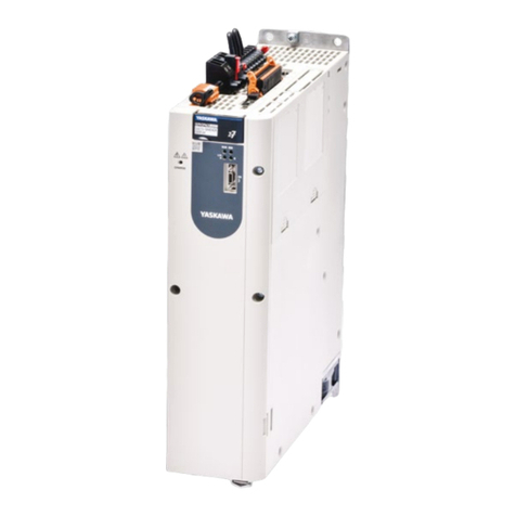
SSD Parvex DIGIVEX Little Drive Servoamplifier Guide

SSD Parvex SAS
8, avenue du Lac - B.P. 249
F-21007 Dijon Cedex
www.SSDdrives.com
DIGIVEX Little Drive
DIGITAL SERVOAMPLIFIER
User and commissioning manual
PVD 3530 GB – 01/2005
This manual was downloaded on www.sdsdrives.com

PRODUCT RANGE
1 - « BRUSHLESS » SERVODRIVES
TORQUE OR POWER
RANGES
• BRUSHLESS SERVOMOTORS, LOW INERTIA, WITH RESOLVER
Very high torque/inertia ratio (high dynamic performance machinery):
⇒ NX -HX - HXA 1 to 320 N.m
⇒ NX - LX 0,45 to 64 N.m
High rotor inertia for better inertia load matching:
⇒ HS - LS 3,3 to 31 N.m
Varied geometrical choice :
⇒ short motors range HS - LS 3,3 to 31 N.m
⇒ or small diameter motors : HD, LD 9 to 100 N.m
Voltages to suit different mains supplies :
⇒ 230V three-phase for «série L - NX»
⇒ 400V, 460V three-phase for «série H -
NX»
• "DIGIVEX DRIVE" DIGITAL SERVOAMPLIFIERS
⇒ SINGLE-AXIS DSD
⇒ COMPACT SINGLE-AXIS DµD, DLD
⇒ POWER SINGLE-AXIS DPD
⇒ MULTIPLE-AXIS DMD
• "PARVEX MOTION EXPLORER" ADJUSTING SOFTWARE
2 - SPINDLE DRIVES
• SPINDLE SYNCHRONOUS MOTORS
⇒ "HV" COMPACT SERIES
From 5 to 110 kW
⇒ "HW" ELECTROSPINDLE,frameless, water-cooled motor
up to 60,000 rpm
• "DIGIVEX" DIGITAL SERVOAMPLIFIERS
3 - DC SERVODRIVES
• "AXEM", "RS" SERIES SERVOMOTORS
0.08 to 13 N.m
• "RTS" SERVOAMPLIFIERS
• "RTE" SERVOAMPLIFIERS for DC motors + resolver giving position
measurement
4 - SPECIAL ADAPTATION SERVODRIVES
• "EX" SERVOMOTORS for explosive atmosphere
• "AXL" COMPACT SERIES SERVOREDUCERS
5 to 700 N.m
5 - POSITIONING SYSTEMS
• Numerical Controls « CYBER 4000 » 1 to 4 axes
• "CYBER 2000" NC 1 to 2 axes
• VARIABLE SPEED DRIVE - POSITIONER
⇒ SINGLE-AXIS DSM
⇒ POWER SINGLE-AXIS DPM
⇒ MULTIPLE-AXIS DMM
• ADJUSTMENT AND PROGRAMMING SOFTWARE PARVEX MOTION EXPLORER
This manual was downloaded on www.sdsdrives.com

DIGIVEX Little Drive Servoamplifier
1
PVD 3530 GB 01/2005
CONTENTS
SAFETY INSTRUCTIONS ……………………………………………………………………………5
PRODUCT RANGE 2
1. GENERAL 7
1.1 Digital Servodrive 7
1.2 General Characteristics 7
1.3 Operating Principle 8
1.3.1 Block diagram 8
1.3.2 Power supply functions 10
1.3.3 Servomotor control functions 10
1.3.3.1 Presentation 10
1.3.3.2 Functions and block diagram 10
1.3.3.3 Forcing logic inputs 12
1.3.3.4 Stimuli / oscilloscope functions 12
1.3.3.5 Speed ramp function 12
1.3.3.6 logic outputs 14
1.3.3.7 Brake action 14
1.3.3.8 Monitoring reasons for stoppage 15
1.3.3.9 General characteristics of the DIGIVEX Little Drive 15
1.4 Compliance with Standards 16
2. ENERGY DISSIPATION 17
2.1 Braking Energy Dissipation 17
2.1.1 Calculating the power to be dissipated in the braking resistor 17
2.1.2 Braking energy dissipation 17
2.1.3 Braking capacity and module losses. 18
This manual was downloaded on www.sdsdrives.com

DIGIVEX Little Drive Servoamplifier
2
PVD 3530 GB 01/2005
2.2 DLD paralleling 19
3. DIMENSIONS, ASSEMBLY, MASS, LABELLING,
CODING 20
3.1 Dimensions, Assembly and Mass 20
3.2 Labelling and Coding 22
4. ELECTRICAL CONNECTIONS 23
4.1 General Wiring Requirements 23
4.1.1 Appliance handling 23
4.1.2 Electromagnetic compatibility 23
4.1.3 DIGIVEX Little Drive Sub-D connectors 24
4.2 Standard Connection Diagram 24
4.3 Description of Terminal Blocks and Sub-D Connector 29
4.3.1 Terminal blocks B1, B2, B3, B4 30
4.3.2 Sub-D connectors X1, X2, X3, X4 30
4.3.2.1 Sub-D connector table 30
4.3.2.2 Sub-D connector X1:"Resolver" 31
4.3.2.3 Sub-D connector X2: Inputs / Outputs 33
4.3.2.4 Sub-D connector X3: encoder emulation 36
4.3.2.5 Encoder emulation cable 36
4.3.2.6 Sub-D connector X4 : RS232 38
4.4 Connection Details 38
4.4.1 Main supply characteristics 38
4.4.2 Power component dimensions 39
4.4.3 Auxiliary power supply 39
4.4.4 Terminal block B1: brake supply 40
4.4.5 Earth connection to the chassis 40
4.4.6 Short-circuit capacity (UL 508 C certification) 40
4.4.7 Fuse specifications (UL 508 C certification ) 40
4.5 Connecting Servomotors 41
4.5.1 Power cable definition 41
4.5.2 Motor end connection 47
4.5.3 Resolver connection 49
4.5.4 Automatic control Input / Output connection 50
4.6 Accessories and Tools 50
4.6.1 Cables 50
This manual was downloaded on www.sdsdrives.com

DIGIVEX Little Drive Servoamplifier
3
PVD 3530 GB 01/2005
5. AUTOMATIC CONTROL INPUT / OUTPUT
FUNCTIONS AND CHARACTERISTICS 51
5.1 Input / Output Characteristics 51
5.1.1 Logic inputs 51
5.1.2 Logic outputs 51
5.1.3 Speed set point input 52
5.1.4 Current limitation input 53
5.1.5 Analog outputs 53
5.1.6 Encoder emulation 54
5.2 RESET and Contactor Control 56
5.3 Initilialization Sequence 57
5.4 Stop Sequence 57
5.4.1 Normal stoppage 57
5.4.2 Stoppage due to a fault 57
6. SERVO-CONTROL PARAMETER FUNCTION AND
SETTING 58
6.1 Servocontrol Parameter Functions 58
6.1.1 List of parameters 58
6.1.2 Regulation selection: current, proportional, PI, PI² 58
6.1.3 Integration stoppage 61
6.1.4 Speed scaling 61
6.1.5 Filtering frequency 61
6.1.6 Predictors 62
6.2 Inputting Parameters 64
6.3 Setting with DIGIVEX PC Software 64
6.3.1 Outline 64
6.3.2 internal variables 65
6.3.3 Entering parameters via DIGIVEX PC software 66
6.3.4 Setting loop parameters for speed regulation 66
6.3.5 Setting predictors 70
6.3.6 Setting current regulation parameters 74
6.3.7 Other characterization parameters 74
7. COMMISSIONING - SERVO-CONTROL PARAMETER
SETTING - DETECTING REASONS FOR STOPPAGE 75
7.1 Start-up Sequence 75
7.1.1 Preliminary checks 75
This manual was downloaded on www.sdsdrives.com

DIGIVEX Little Drive Servoamplifier
4
PVD 3530 GB 01/2005
7.1.2 Commissioning with DIGIVEX PC software 75
7.2 Detecting Reasons for Stoppage 76
7.2.1 Fault display - drive function 76
7.2.1.1 Handling operational malfunctions 77
7.2.1.2 Current monitoring 77
7.2.1.3 Temperature monitoring 78
7.2.1.4 Monitoring the DC Bus voltage 78
7.2.1.5 Other monitoring 78
7.2.1.6 7-segment display 79
7.2.1.7 Corrective actions 80
7.3 Defaults description 81
8. APPENDIX 83
Characteristics and dimensions subject to change without notice.
SSD Parvex SAS
8 Avenue du Lac / B.P 249 / F-21007 Dijon Cedex
Tél. : +33 (0)3 80 42 41 40 / Fax : +33 (0)3 80 42 41 23
www.SSDdrives.com
YOUR LOCAL CORRESPONDENT
This manual was downloaded on www.sdsdrives.com

DIGIVEX Little Drive Servoamplifier
5
PVD 3530 GB 01/2005
SAFETY
Servodrives present two main types of hazard :
- Electrical hazard
Servoamplifiers may contain non-insulated live AC or DC
components. Users are advised to guard against access to live
parts before installing the equipment.
Even after the electrical panel is de-energized, voltages may be
present for more than a minute, until the power capacitors have
had time to discharge.
Specific features of the installation need to be studied to prevent
any accidental contact with live components :
- Connector lug protection ;
- Correctly fitted protection and earthing features ;
- Workplace insulation
(enclosure insulation humidity, etc.).
General recommendations :
• Check the bonding circuit;
• Lock the electrical cabinets;
• Use standardised equipment.
- Mechanical hazard
Servomotors can accelerate in milliseconds. Moving parts must be
screened off to prevent operators coming into contact with them.
The working procedure must allow the operator to keep well clear
of the danger area.
All assembly and commissioning work must be done by qualified
personnel who are familiar with the safety regulations (e.g. VDE
0105 or accreditation C18510).
This manual was downloaded on www.sdsdrives.com

DIGIVEX Little Drive Servoamplifier
6
PVD 3530 GB 01/2005
Upon delivery
All servoamplifiers are thoroughly inspected during manufacture and tested at length before
shipment.
• Unpack the servoamplifier carefully and check it is in good condition.
• Also check that data on the manufacturer's plate complies with the data on the order
acknowledgement.
If equipment has been damaged during transport, the addressee must file a complaint with the
carrier by recorded delivery mail within 24 hours.
Caution:
The packaging may contain essential documents or accessories, in particular :
• User Manual,
• Connectors.
Storage
Until installed, the servoamplifier must be stored in a dry place safe from sudden temperature
changes so condensation cannot form.
Special instructions for setting up the equipment
CAUTION
For this equipment to work correctly and safely it must be
transported, stored, installed and assembled in accordance with
this manual and must receive thorough care and attention.
Failure to comply with these safety instructions may lead to
serious injury or damage.
The cards contain components that are sensitive to electrostatic
discharges. Before touching a card you must get rid of the static
electricity on your body. The simplest way to do this is to touch a
conductive object that is connected to earth (e.g. bare metal
parts of equipment cabinets or earth pins of plugs).
This manual was downloaded on www.sdsdrives.com

DIGIVEX Little Drive Servoamplifier
7
PVD 3530 GB 01/2005
1. GENERAL
1.1 Digital Servodrive
All of the drives comprise:
Brushless servomotors with permanent magnets, sine-wave e.m.f. and resolver-based position
measurement (NX, LX, LS, LD range servomotors)
A box-type electronic control system including:
A power supply function for (depending on the model):
- 230 V single-phase mains supply or 230 V three-phase mains
supply
A control function corresponding to the servomotor (power and resolver) for spindle drive motor
control.
This module also controls energy discharge via internal.
Two connection options are available for these servomotors:
Terminal box + resolver connector.
Power connector + resolver connector.
1.2 General Characteristics
Input voltage rating: 230V (see § 4.4.1)
TYPE MAINS
SUPPLY
CONTROLLABLE
POWER
SINE PEAK
PERMANENT
CURRENT
PEAK
MAXIMUM
CURRENT
REF. PARVEX
DLD 2/4
230 V –
single-
phase
50/60 Hz
375 W 2 A 4 A DLD13M02R
DLD 4/8
230 V –
single-
phase
50/60 Hz
750 W 4 A 8 A DLD13M04R
DLD 2/4
230 V –
three-
phase
50/60 Hz
375W 2 A 4 A DLD13002R
DLD 4/8
230 V –
three-
phase
50/60 Hz
750W 4 A 8 A DLD13004R
DLD 7.5/15
230 V –
three-
phase
50/60 Hz
1,5kW 7.5 A 15 A DLD13007R
This manual was downloaded on www.sdsdrives.com

DIGIVEX Little Drive Servoamplifier
8
PVD 3530 GB 01/2005
1.3 Operating Principle
1.3.1 Block diagram
The block diagram shows two parts:
A power supply section providing dc voltage to the power bridge and auxiliary power supplies
(regulation, fans).
one part for axis control and monitoring control.
This manual was downloaded on www.sdsdrives.com

DIGIVEX Little Drive Servoamplifier
9
PVD 3530 GB 01/2005
MOTOR
POWER
PROTECTIONS
MANAGEMENT
CHOPPED
SUPPLY
A
UXILIARIES POWER OK
BUS VOLTAGE
RESET
+/- 15V
5V
AXE
OK
INIT
C = 0
DRIVE
REGULATION
FANS
RESOLVER
THERMAL
PROTECTION
MOTOR
24V BRAKE
SUPPLY
24V
BRAKE
L1/L
L2/N
L3
U
V
W
SUB-D
SUB-D I/O AND
SET POINT
POWER
MONITORING BRAKE
VOLTAGE
DRV OK
CTN
AUX 1
AUX 2
This manual was downloaded on www.sdsdrives.com

DIGIVEX Little Drive Servoamplifier
10
PVD 3530 GB 01/2005
1.3.2 Power supply functions
Receives the 230 V mains supply through terminal block B3 and converts it into a 325V dc
voltage.
Receives the 230V monophase mains supply through the same B3 terminal block for powering
the auxiliary power supplies (+/-15V, 5V) required by safety regulations.
May receive a 24 V supply via terminal block B1 for powering the motor brake.
1.3.3 Servomotor control functions
1.3.3.1 Presentation
The DIGIVEX Little Drive (DLD) servo-amplifier is a 4-quadrant, transistor control module for
controlling (brushless) synchronous motors with resolvers.
NX, LX, LS, LD spindle drive motors. See separate documentation (PVD3407 and PVD3535).
The customization of the motor - resolver unit and the setting of the servocontrol parameters are
carried out using a PC with DIGIVEX software (PME software, DIGIVEX module), under
Windows.
These parameters are stored in an EEPROM permanent memory.
1.3.3.2 Functions and block diagram
See next page. The diagram shows the main drive functions and the setting parameters.
This manual was downloaded on www.sdsdrives.com

DIGIVEX Little Drive Servoamplifier
11
PVD 3530 GB 01/2005
On the right of the diagram, the motor - resolver - power section.
Parameters can be set for:
⇒ the choice of motor, which dictates the drive rating.
⇒ the general characteristics of the resolver.
The choice of the motor - drive combination determines a number of parameters: current
limitation, I2= f(t) protection, standard servo-control parameters.
Ahead of current control.
♦ Second order filter for reducing the effect of high-frequency resonance
♦ External reduction of current limitation
Resolver numerical processing (non parametric) and the encoder emulation function (number of
lines adjustable from 1 to 16384).
Choice of type of regulation: torque or speed.
In speed loop. Parameters can be set for :
⇒ maximum speed for the application (limited by the maximum motor speed).
⇒ scaling (1 V = N rpm).
⇒ choice of corrector type: proportional, proportional and integral, proportional and
double integration.
Predictive actions associated with speed control.
These actions, acting outside the speed loop, directly affect torque. As they are external they
have little effect on loop stability. However, they allow anticipated actions, without waiting for the
speed loop reaction.
The predictive actions (or predictors) are:
Gravity: compensation for vertical masses.
Dry friction: a friction force value is fixed. The corresponding torque set point is applied, its sign
being that of the speed set point.
Viscous friction: compensation for friction forces that are proportional to speed (hydraulic or
electrical system drive).
Acceleration: changes in the speed set point (drift) are monitored and direct action is taken on
the torque set point via a coefficient K, the inertia image.
The analog input speed reference (13 bits + sign), non parametric.
On the left of the block diagram, the set of logic and analog inputs / outputs.
The parameter setting software is used:
for allocating some of these Inputs / Outputs.
for forcing them to a logic status. The inputs are then disconnected from the outside.
This manual was downloaded on www.sdsdrives.com

DIGIVEX Little Drive Servoamplifier
12
PVD 3530 GB 01/2005
1.3.3.3 Forcing logic inputs
The software allows the logic input to be forced to a value. Consequently, via the software, the
SPEED RANGE, CW, CCW, TORQUE inputs are able to:
"disconnect" them from the physical input.
force them by software to 0 or 1.
1.3.3.4 Stimuli / oscilloscope functions
Certain functions integrated in the drive allow the speed set point to be excited: dc voltage,
square (response at one scale), sine.
These stimuli are activated by a PC. Their result, stored in the amplifier, can be seen on the PC
screen by using the oscilloscope function (a maximum of 4 variables can be displayed
simultaneously via the PME DIGIVEX software).
1.3.3.5 Speed ramp function
A ramp function is integrated into the drive unit for versions of software above AP516V07, running
with PME version 4.04 or above. This function is used to create time dependent linear speed
ramps. Parameters can be set in “Servo-control settings” under the “ramp” tab:
- Times t1, t2, t3, and t4 can be programmed from 0 to 1000s.
- Speeds Vp and Vn can be programmed from 0 to 50,000 rpm.
Comment:
Vp and Vn are points on the ramp; they can be defined outside of maximum motor speed.
However, servo-controls will limit the motor speed to the maximum authorized speed.
This manual was downloaded on www.sdsdrives.com

DIGIVEX Little Drive Servoamplifier
13
PVD 3530 GB 01/2005
How the ramp operates:
The ramp input can either be the analog input instruction or the stimuli generator as shown below:
In the event that the input is analog, scaling is carried out by the input instruction product (V) * speed
range for 1V, the speed range for 1 volt can be found in the servo-control dialogue box.
Ramp activation is validated by the information “TORQUE=1” (enable torque activated).
Therefore, the ramp operates as soon as the zero torque information is unlocked and an operating
direction (CW or CCW) selected. When CW or CCW is deactivated, the motor decelerates in
accordance with the pre-set ramp which means that CW or CCW cannot be selected as
mechanical stops.
Important remarks:
- When “TORQUE” is successively deactivated and reactivated, the speed is reduced to
zero prior to following the progression of the ramp.
- The ramp function must be deactivated when a DLD with digital control is used to carry
out a check on the axis position.
Scaling
Input
instruction
Stimuli
generator
Speed
ramp
To speed
servo-controls
ON/OFF stimuli
This manual was downloaded on www.sdsdrives.com

DIGIVEX Little Drive Servoamplifier
14
PVD 3530 GB 01/2005
1.3.3.6 logic outputs
Speed detection
The OUT1 output status acts in the following manner:
Criterion OUT1
Speed < Threshold (OUT1) 1
Speed > Threshold (OUT1) 0
NB: 19 rpm ≤threshold (OUT1) ≤100,000 rpm
Speed reached
OUT2 output changes to 1 status when the motor speed is within the range given by + or -
the Threshold (OUT2) value:
(input instruction – threshold (OUT2) < actual speed < input instruction + threshold (OUT2)
NB: 48 rpm ≤threshold (OUT2) ≤5252 rpm
1.3.3.7 Brake action
The drive can be declared in the parameters with a brake function.
The 24 V brake supply (terminal block B1) is monitored by the drive.
24 V present: Axis under torque. Removal of limitation of 90% of rated motor current.
24 V absent: Axis at reduced torque with 90% of rated motor current.
The brake engage or release order is in no event given by the drive but by the external control.
The control can monitor the drive outputs indicating zero speed to decide whether or not to apply
the brake.
± Limit (OUT2)
± Limit (OUT2)
This manual was downloaded on www.sdsdrives.com

DIGIVEX Little Drive Servoamplifier
15
PVD 3530 GB 01/2005
1.3.3.8 Monitoring reasons for stoppage
This monitoring may, through strategic choice, entail either stoppage or reduced performance for
certain faults related to current.
Variables monitored :
Mean drive current.
Output current (short-circuit).
Dissipater temperature.
Motor temperature.
Ambient temperature.
Overspeed.
No resolver.
Maximum and minimum dc bus voltages.
1.3.3.9 General characteristics of the DIGIVEX Little Drive
Power reduction with altitude
A
bove 1000 m, service power falls by 1% for every 100 m up
to a maximum altitude of 4000 m
Operating temperature
relative humidity
Normal use: 0 - 40°C
A
bove 40°C, service power falls by 20% for every 10°C up to
a maximum temperature of 60°C.
The variable speed drive stops when the ambient temperature
exceeds 60°C.
85% (without condensation)
Storage temperature -30°C to +85°C
Chopping frequency 8 kHz
Current bandwidth 600Hz to -3dB
Speed bandwidth Up to 200Hz
Minimum speed Minimum speed 0.05 rpm or 1/8000th of maximum speed
Maximum speed Driven by DIGIVEX : 100 000 rpm
Speed static precision for load
variation from 0 to In and for
rated voltage of DIGIVEX Little
Drive
With analog set point: 1% whatever the speed
Electrical protection
Electrical isolation of power bridge
Mean current protection depending on drive rating
Pulse current protection of drive and motor
rms current protection of motor
Protection against short circuits at bridge output
Mechanical protection IP20 under IEC 529
Pollution degree UL : 2
To rise in a surrounding wall
Other monitoring
Motor temperature
Drive temperature
Resolver power supply
Brake supply
This manual was downloaded on www.sdsdrives.com

DIGIVEX Little Drive Servoamplifier
16
PVD 3530 GB 01/2005
1.4 Compliance with Standards
DIGIVEX Little Drive
CE Marking
DIGIVEX Little Drive products have the CE marking under the European Directive 89/336/EEC as
amended by Directive 93/68/EEC on electromagnetic compatibility as well as under the Electrical
Safety Directive or Low Voltage Directive 73/23/EEC amended by Directive no. 93/68/EEC.
The Directive concerning electromagnetic compatibility invokes the harmonized generic standards
EN 50081-2 of December 1993 (Electromagnetic Compatibility – Emission Generic Standard –
Industrial Environment) and EN 50082-2 of June 1995 (Electromagnetic Compatibility – Immunity
Generic Standard – Industrial Environment). These two harmonized generic standards are based
on the following reference standards:
• EN 55011 of July 1991: Radiated and line conducted emissions.
• ENV 50140 of August 1993 and ENV 50204: Immunity to radiated electromagnetic fields.
• EN 61000-4-8 of February 1994: Power frequency magnetic fields.
• EN 61000-4-2 of June 1995: Electrostatic discharge.
• ENV 50141 of August 1993: Disturbances induced in cables.
• EN 61000-4-4 of June 1995: Rapid transients.
The Low Voltage Directive groups all the electrical safety standards together including the EN
60204-1 Standard which covers electrical fittings on industrial machinery.
Compliance with the reference standards above implies observance of the wiring instructions and
diagrams provided in this technical documentation which accompanies all equipment.
Incorporation in a machine
The design of this equipment allows it to be used in a machine subject to Directive 98/37/EC of
22/06/98 (Machinery Directive), provided that its integration (or incorporation and/or assembly) is
done in accordance with trade practices by the machine manufacturer and in accordance with the
instructions in this booklet.
UL Certification
DIGIVEX Little Drive products are covered by UL and cUL certificate (see section 8).
This manual was downloaded on www.sdsdrives.com

DIGIVEX Little Drive Servoamplifier
17
PVD 3530 GB 01/2005
2. ENERGY DISSIPATION
The energy a module has to dissipate is broken down into:
Energy generated by braking.
Energy from rectifier and power bridge losses.
2.1 Braking Energy Dissipation
2.1.1 Calculating the power to be dissipated in the braking resistor
The permanent and pulse power levels given in the table below are limited by the characteristics
of the "breaking" resistors.
When the application includes intensive cycles or long-duration decelerations, the mean power to
be dissipated by each axis must be calculated.
P in Watts = J
2
N
9.55
2
⎛
⎝
⎜⎞
⎠
⎟.f
J : Moment of inertia of the servomotor and the related load in kgm².
N : Angular speed of motor shaft at start of braking, in rpm.
f : repeat frequency of braking cycles in s-1.
This formula is for the least favourable case. For a mechanism with substantial friction or with low
reverse output, the power to be dissipated may be greatly reduced.
.
The power to be dissipated by the axis must not exceed the permanent power admissible by the
resistor. Duration and repetition must not exceed the ratings in table § 2.1.3.
2.1.2 Braking energy dissipation
Dissipation of breaking energy is carried out through a resistor (or 2 resistors depending on the
calibre) situated in the module.
This manual was downloaded on www.sdsdrives.com

DIGIVEX Little Drive Servoamplifier
18
PVD 3530 GB 01/2005
2.1.3 Braking capacity and module losses.
230 V single-phase or three-phase modules.
MODULE RATING
2/4 4/8 7.5/15
Resistor value
Maximum current
Pulse power
Permanent power
Maximum non repetitive duration
Repetition
Losses from modules (at
maximum power)
Low level consumption
Ω
A
kW
W
s
%
W
W
100
3.8
1.2
20
0,2
1,6
15
10
100
3.8
1.2
30
0,2
2,5
25
10
50
7.6
2.4
40
0,2
1,6
50
10
Definitions
Maximum power: Maximum power drawn, resistance connecting is carried out at 360V, hence,
the power drawn has a maximum resistance value equal to 360.
Pulse power: maximum power dissipated by the resistor, this power can only be drawn for a
short time and in compliance with a certain cycle.
Permanent power (to 25°C) : mean power that can be dissipated on a permanent basis by the
resistor.
Maximum duration: maximum duration, in seconds, for which the pulse power can be required
(starting from cold); the resistor must be allowed to cool down before braking again.
Module losses: losses specific to the module, the value shown in the table is that obtained when
the module is used at maximum power.
Low-level consumption: consumption of the low-level power supplies in Watts.
This manual was downloaded on www.sdsdrives.com
Table of contents
