manuals.online logo
Brands
  1. Home
  2. •
  3. Brands
  4. •
  5. Danfoss
  6. •
  7. Servo Drive
  8. •
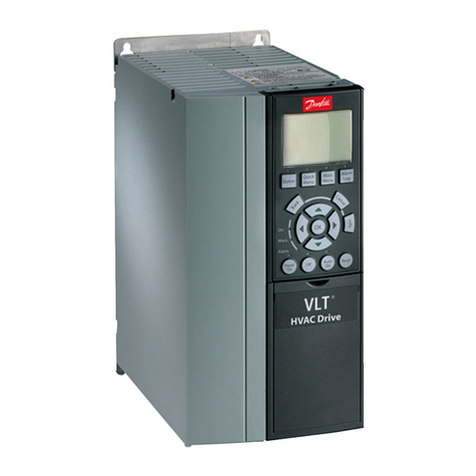
  9. Danfoss 176F6617 User manual

Danfoss 176F6617 User manual

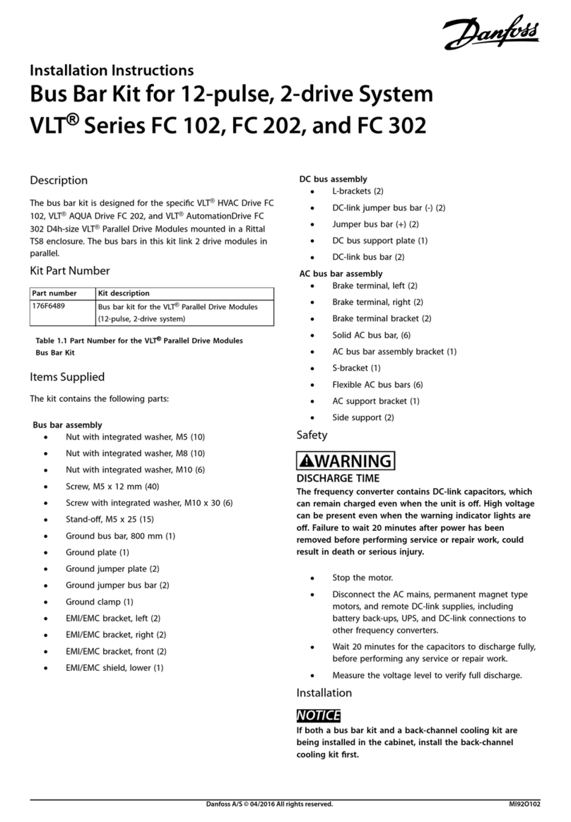
Description
The in-back/out-back cooling kit ts the following drives in
E1h/E2h enclosures:
•
VLT
®
HVAC Drive FC 102
•
VLT
®
Refrigeration Drive FC 103
•
VLT
®
AQUA Drive FC 202
•
VLT
®
AutomationDrive FC 302
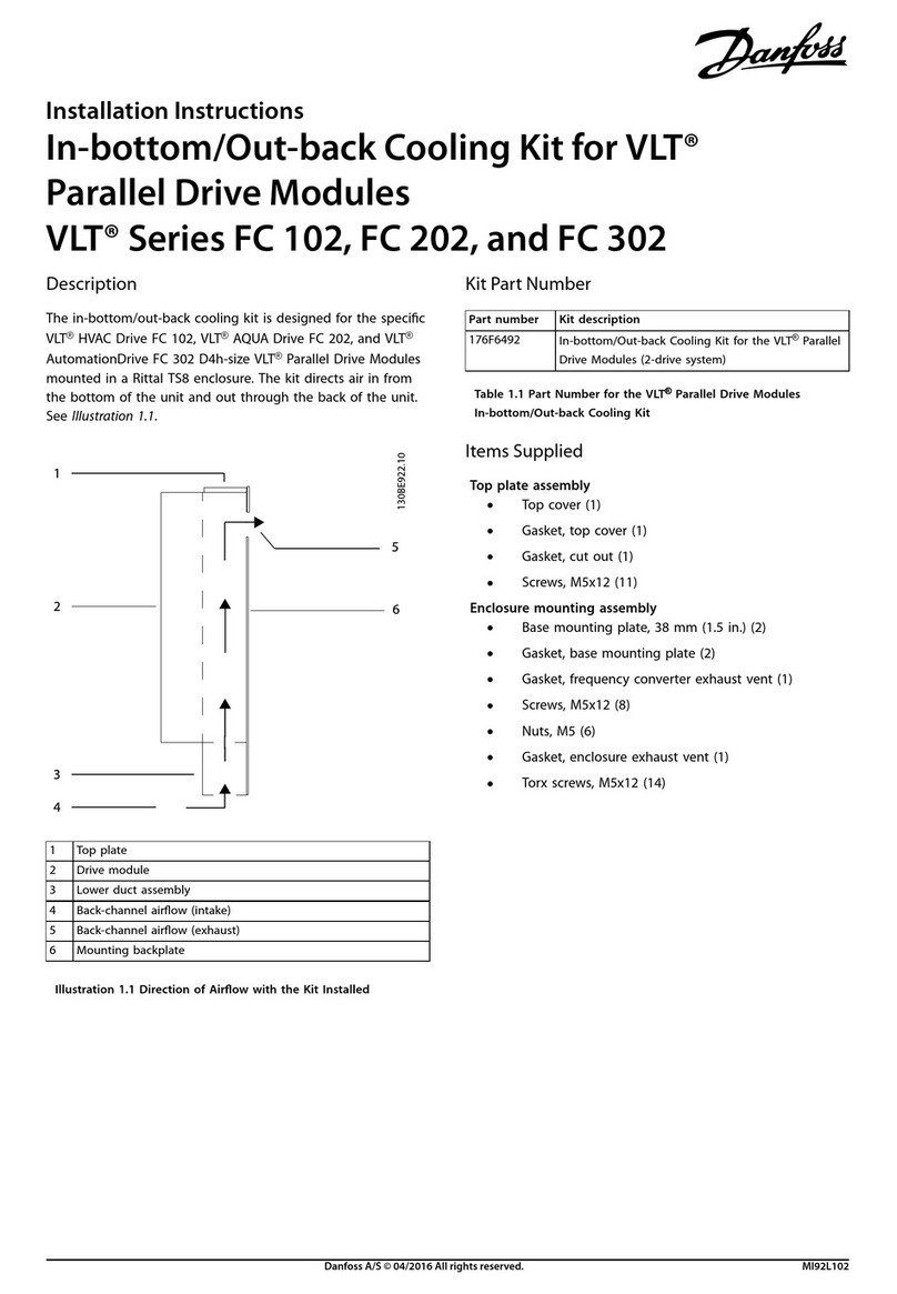
When the kit is installed, air ows into the lower back duct
and out through the upper back duct of the drive. See
Illustration 1.1.
1 Top cover plate 4 Cooling channel
2 Enclosure 5 Airow direction
3 Pedestal 6 Bottom cover plate
Illustration 1.1 Direction of Airow with Kit Installed
Kit Part Numbers
Use these instructions with the following cooling kits.
Kit number Kit description
176F6617 In-back/out-back cooling kit for E1h drive
176F6618 In-back/out-back cooling kit for E2h drive
Table 1.1 Part Numbers for Cooling Kits
Items Supplied
The in-back/out-back cooling kit contains the following items.
Item Quantity
Top cover plate 1
Top gasket 1
Bottom cover plate 1
Bottom gasket 1
M5x14 screws 8–10
Table 1.2 Items Supplied in Cooling Kit
Safety Information
WARNING
DISCHARGE TIME
The drive contains DC-link capacitors, which can remain
charged even when the drive is not powered. High voltage
can be present even when the warning LED indicator lights
are o. Failure to wait 40 minutes after power has been
removed before performing service or repair work can result
in death or serious injury.
•
Stop the motor.
•
Disconnect AC mains and remote DC-link power
supplies, including battery back-ups, UPS, and DC-
link connections to other drives.
•
Disconnect or lock PM motor.
•
Wait 40 minutes for capacitors to discharge fully.
•
Before performing any service or repair work, use
an appropriate voltage measuring device to make
sure that the capacitors are fully discharged.
Installation Instructions
In-back/Out-back Cooling Kit for E1h/E2h Drives
VLT®Series FC 102, FC 103, FC 202, and FC 302
Danfoss A/S © 09/2017 All rights reserved. MI35D102
WARNING
ELECTRICAL SHOCK HAZARD
VLT
®
series drives contain dangerous voltages when
connected to mains voltage. Improper installation, and
installing or servicing with power connected, can cause
death, serious injury, or equipment failure.
To avoid death, serious injury, or equipment failure:
•
Only use qualied electricians for the installation.
•
Disconnect the drive from all power sources before
installation or service.
•
Treat the drive as live whenever the mains voltage
is connected.
•
Follow the guidelines in these instructions and local
electrical safety codes.
NOTICE
APPLYING GASKETS
This kit contains gaskets to ensure a proper seal between
metal parts. Before adhering a gasket to a part, check that
the part matches the gasket and that no holes are covered.
Installation Instructions
Installing the Top Cover Plate
To install the top cover plate of the cooling kit, use the
following procedure. See Illustration 1.2.
1. Remove paper backing from the top gasket to
expose the adhesive. Adhere the top gasket to the
underside of the top cover plate.
2. Remove 6 M5x12 screws (T25) surrounding the sides
and back of the vent in the top surface of the drive
enclosure. Retain the screws.
3. Loosen 3 M5x12 screws (T25) at the front of the vent
in the top surface of the drive enclosure.
4. Slide the edge of the top cover plate under the 3
loosened screws, positioning the plate over the vent
in the top surface of the enclosure.
5. Secure the top cover plate to the enclosure with the
6 M5x12 screws (T25) removed previously. Torque
fasteners to 2.3 Nm (20 in-lb).
Installation Instructions In-back/Out-back Cooling Kit for E1h/E2h Drives
VLT
®
Series FC 102, FC 103, FC 202, and FC 302
2
Danfoss A/S © 09/2017 All rights reserved. MI35D102
1M5x12screw 4Topvent
2 Top cover plate 5 Front screws (loosened, not removed)
3 Gasket between drive enclosure and top cover plate 6 Top surface of enclosure
Illustration 1.2 Installation of Top Cover Plate
Installation Instructions In-back/Out-back Cooling Kit for E1h/E2h Drives
VLT
®
Series FC 102, FC 103, FC 202, and FC 302
MI35D102 Danfoss A/S © 09/2017 All rights reserved.
3
Installing the Bottom Cover Plate (with Pedestal Attached)
The bottom cover can be installed either before or after the
pedestal is attached to the drive enclosure. The following
procedure describes how to install the bottom cover plate
with the pedestal attached. See Illustration 1.3. If the pedestal
has not been attached, continue to the next procedure.
1. Remove paper backing from the bottom gasket.
Adhere the bottom gasket to the upper side of the
bottom cover plate.
2. Remove the front panel of the pedestal by removing
4 M5x12 screws. Retain the screws.
3. Inside the pedestal, position the bottom cover plate
and gasket over the opening at the bottom of the
cooling channel.
4. Secure the bottom cover plate using the M5x14
screws (T25) included with the kit. Installation in E1h
drives requires 8 screws, and installation in E2h drives
requires 10 screws. Torque screws to 2.3 Nm (20 in-
lb).
5. Replace the pedestal front panel and secure with 4
M5x12 screws previously removed.
1 Drive enclosure 4 Pedestal
2 M5x12 screw 5 M5x14 screw
3 Front panel of pedestal 6 Bottom cover plate
Illustration 1.3 Bottom View of Drive Enclosure and Pedestal
Installation Instructions In-back/Out-back Cooling Kit for E1h/E2h Drives
VLT
®
Series FC 102, FC 103, FC 202, and FC 302
4
Danfoss A/S © 09/2017 All rights reserved. MI35D102
Installing the Bottom Cover Plate (before Attaching Pedestal)
The bottom cover plate can be installed either before or after
the pedestal is attached to the drive enclosure. The following
procedure explains how to install the bottom cover plate
before attaching the pedestal to the drive. See Illustration 1.4.
1. Remove paper backing from the bottom gasket.
Adhere the bottom gasket to the upper side of the
bottom cover plate.
2. Position the bottom cover plate and gasket over the
opening at the lower end of the cooling channel.
3. Secure the bottom cover plate using the M5x14
screws (T25) provided with the kit. Installation in E1h
drives requires 8 screws, and installation in E2h drives
requires 10 screws. Torque screws to 2.3 Nm (20 in-
lb).
1 Cooling channel 4 M5x14 screw
2 Bottom gasket 5 Pedestal
3 Bottom cover plate 6 M10x30 fastener
Illustration 1.4 Installation of Bottom Cover Plate and Pedestal
Installation Instructions In-back/Out-back Cooling Kit for E1h/E2h Drives
VLT
®
Series FC 102, FC 103, FC 202, and FC 302
MI35D102 Danfoss A/S © 09/2017 All rights reserved.
5
Attaching the Drive Enclosure to the Pedestal
After installing the bottom cover plate, attach the pedestal to
the drive enclosure if it is not attached. To attach the pedestal
to the drive enclosure, use the following procedure. Refer to
Illustration 1.5 and Illustration 1.6.
1. Lift the drive and position it on the pedestal. There
are 2 bolts in the rear of the pedestal that slide into
the 2 slotted holes in the rear of the enclosure.
Position the drive by adjusting the bolts up or down.
Loosely secure with 2 M10 nuts and locking brackets.
See Illustration 1.5.
2. Around the top of the pedestal, secure the enclosure
using 6 M10x30 fasteners. See Illustration 1.6. Loosely
tighten each bolt until all bolts are installed.
3. Fasten each bolt securely and torque to 19 Nm (169
in-lb).
4. Torque the 2 M10 nuts at the rear of the enclosure to
19 Nm (169 in-lb).
5. Ensure that the air intake and exhaust vents at the
back of the enclosure are not obstructed. Refer to
Illustration 1.7 and Illustration 1.8.
1Enclosure
2 Pedestal
3M10nut
4 Slotted hole in enclosure
5 Bolt at rear of pedestal
6Lockingbracket
Illustration 1.5 Pedestal to Enclosure Back Mounting Points
1Enclosure
2 Pedestal
3 M10x30 fasteners (rear corner bolts not shown)
Illustration 1.6 Pedestal to Enclosure Mounting Points
Installation Instructions In-back/Out-back Cooling Kit for E1h/E2h Drives
VLT
®
Series FC 102, FC 103, FC 202, and FC 302
6
Danfoss A/S © 09/2017 All rights reserved. MI35D102
E1h Drive Back Exterior Dimensions
Illustration 1.7 Back View of E1h Drive
E2h Drive Back Exterior Dimensions
Illustration 1.8 Back View of E2h Drive
Installation Instructions In-back/Out-back Cooling Kit for E1h/E2h Drives
VLT
®
Series FC 102, FC 103, FC 202, and FC 302
MI35D102 Danfoss A/S © 09/2017 All rights reserved.
7
Danfoss can accept no responsibility for possible errors in catalogues, brochures and other printed material. Danfoss reserves the right to alter its products without notice. This also applies to products already on
order provided that such alterations can be made without subsequential changes being necessary in specifications already agreed. All trademarks in this material are property of the respective companies. Danfoss
and the Danfoss logotype are trademarks of Danfoss A/S. All rights reserved.
Danfoss A/S
Ulsnaes 1
DK-6300 Graasten
vlt-drives.danfoss.com
*MI35D102*
MI35D102130R0756 09/2017

This manual suits for next models

1

Other Danfoss Servo Drive manuals

Danfoss VLT FC 103 User manual

Danfoss

Danfoss VLT FC 103 User manual

Danfoss 176F6619 User manual

Danfoss

Danfoss 176F6619 User manual

Danfoss VLT AutomationDrive FC 302 User manual

Danfoss

Danfoss VLT AutomationDrive FC 302 User manual

Danfoss VLT AutomationDrive FC 360 User manual

Danfoss

Danfoss VLT AutomationDrive FC 360 User manual

Danfoss 176F6609 User manual

Danfoss

Danfoss 176F6609 User manual

Danfoss 176F6493 User manual

Danfoss

Danfoss 176F6493 User manual

Danfoss VLT ISD 410 User manual

Danfoss

Danfoss VLT ISD 410 User manual

Danfoss VLT HVAC Drive FC 102 Guide

Danfoss

Danfoss VLT HVAC Drive FC 102 Guide

Danfoss VLT ISD Connection Box User manual

Danfoss

Danfoss VLT ISD Connection Box User manual

Danfoss VLT Integrated Servo Drive ISD 510 System Guide

Danfoss

Danfoss VLT Integrated Servo Drive ISD 510 System Guide

Danfoss 176F3166 User manual

Danfoss

Danfoss 176F3166 User manual

Danfoss AMV 655 User manual

Danfoss

Danfoss AMV 655 User manual

Danfoss VLT Integrated Servo Drive ISD 510 System User manual

Danfoss

Danfoss VLT Integrated Servo Drive ISD 510 System User manual

Danfoss 176F6748 User manual

Danfoss

Danfoss 176F6748 User manual

Danfoss VLT HVAC Drive FC 102 User manual

Danfoss

Danfoss VLT HVAC Drive FC 102 User manual

Danfoss VLT Midi Drive FC 280 User manual

Danfoss

Danfoss VLT Midi Drive FC 280 User manual

Danfoss VLT ISD 511 User manual

Danfoss

Danfoss VLT ISD 511 User manual

Danfoss AME 25 User manual

Danfoss

Danfoss AME 25 User manual

Danfoss VLT Integrated Servo Drive ISD 510 System User manual

Danfoss

Danfoss VLT Integrated Servo Drive ISD 510 System User manual

Danfoss 176F6492 User manual

Danfoss

Danfoss 176F6492 User manual

Danfoss VLT 6002-6011 User manual

Danfoss

Danfoss VLT 6002-6011 User manual
Danfoss VLT series Operating instructions
Danfoss

Danfoss VLT series Operating instructions

Danfoss 176F6491 User manual

Danfoss

Danfoss 176F6491 User manual

Danfoss 176F6764 User manual

Danfoss

Danfoss 176F6764 User manual
Popular Servo Drive manuals by other brands

Kollmorgen AKD series installation manual

Kollmorgen

Kollmorgen AKD series installation manual

Jenaer ECOVARIO 114 D Installation and operating instructions

Jenaer

Jenaer ECOVARIO 114 D Installation and operating instructions

Siemens MICROMASTER 440 quick start guide

Siemens

Siemens MICROMASTER 440 quick start guide

Eurotherm 637 Series product manual

Eurotherm

Eurotherm 637 Series product manual

Motor Power Company DUET_FL 48/10 user manual

Motor Power Company

Motor Power Company DUET_FL 48/10 user manual

IMI TA MC15/230 Mounting instructions

IMI TA

IMI TA MC15/230 Mounting instructions

Unitek TVD6-200bl manual

Unitek

Unitek TVD6-200bl manual

Baldor Flex+DriveII installation manual

Baldor

Baldor Flex+DriveII installation manual

Inovance SV660F Series installation guide

Inovance

Inovance SV660F Series installation guide

Metronix ARS 2100 SE Mounting instruction

Metronix

Metronix ARS 2100 SE Mounting instruction

Beckhoff AX8000 operating instructions

Beckhoff

Beckhoff AX8000 operating instructions

IMI MC50/24-C Mounting instructions

IMI

IMI MC50/24-C Mounting instructions

Beckhoff AX8000 System manual

Beckhoff

Beckhoff AX8000 System manual

Inovance IS580 Series user manual

Inovance

Inovance IS580 Series user manual

Mesa MQC Series operating manual

Mesa

Mesa MQC Series operating manual

GFA ELEKTROMAT SI 17.60 FU-25,40 installation instructions

GFA

GFA ELEKTROMAT SI 17.60 FU-25,40 installation instructions

Omron R88M-K Series user manual

Omron

Omron R88M-K Series user manual

LinMot E1200 Series installation guide

LinMot

LinMot E1200 Series installation guide

manuals.online logo
manuals.online logoBrands
  • About & Mission
  • Contact us
  • Privacy Policy
  • Terms and Conditions

Copyright 2025 Manuals.Online. All Rights Reserved.