SSF BII Electronics TRIPTYCH User manual

BII Electronics x SSF: TRIPTYCH
Introducing BII Electronics, a new maker of modular tools for music creation
and sound destruction.
Founded by musicians and friends Boys Noize and Baseck, BII is driven by a
shared obsession with Eurorack-based processes, bringing ideas to reality through
collaboration with the world's best specialist hardware manufacturers.
Two artists, with combined decades of sound design, music production, and
live performance experience, joined by one innovator in engineering and manufac-
turing. This team of three's collective inspiration and individual insights are embod-
ied in the form and function of every BII instrument. With this partnership in mind, it
is tting that BII's inaugural module carries the name "TRIPTYCH."
TRIPTYCH was imagined through hands-on practice -- the discovery of a
unique chain of three devices generating sounds of incomparable timbral character,
and an anity for compact modules with an all-analogue signal path.
Already enthusiasts of the craftsmanship of New York-based hardware
producer Steady State Fate, Boys Noize and Baseck invited SSF designer Andrew
Morelli to collaborate on BII's rst module. The newly formed trio's combined knowl-
edge and uncompromising attention to detail resulted in a bespoke, completely
integrated module that surpassed expectations: Distortion (3x), Flange/Comb, and
Filter, with all paths internally re-routable. TRIPTYCH was born.
Three collaborators, three eects, and endless possibilities - we look forward
to hearing what you discover as you unfold BII Electronic's TRIPTYCH.
Synopsis ................................................ page 1
Connecting power ............................... page 1
Triptych Feature Map .......................... page 2
Features Explained ............................. page 3-4
Signal Path Routing ........................... page 5-6
APPENDIX ........................................... page 7

Triptych is a multi-tiered module consisting of a trio of internally re-routable eects with the addition of
input and output voltage-controlled ampliers. From distortion to karplus-strong and polyphonic resonance,
Triptych is designed to be a unique sound shaping and transformation tool – from subtle to extreme via a fully
analog signal path.
Triptych was inspired by guitar pedal eect chains used by Boys Noize involving a distortion, anger
and lter as a model. Rather than clone these eects, I set out to design my own versions that complement the
signature sounds of the BII artists. Being a eurorack device, we wanted to preserve the capability to re-patch
these eects in the most useful ways and hence devised a complex switching scheme to alter the signal path
and dramatically increase the complexity of sound design potential. Adding the ability to voltage control just
about every parameter, a multitude of dynamism and expressiveness truly unfolded beyond our expectations.
I encourage you to experiment with Triptych and nd new ways to explore it’s many facets. Whether
using it as a distortion or eect, oscillator or character lter - I hope you will nd Triptych as rewarding and
inspiring as we have during it’s development. -A.M. SSF
Power Consumption: +119mA, -95mA
SYNOPSIS
CONNECTING POWER and PRECAUTIONS
Remove the included power supply cable and take note of the side
of the cable with the RED stripe.
Locate the 10pin power header on Triptych and note the side
marked -12V, RED and connect the RED side of the power cable to
that side of the power header.
Triptych is reverse power protected so don't freak out if you do this
wrong for some reason...
Mount the module in your rack using the provided harware or your own fancy bits. It is important to
note that Triptych involves many high gain stages, multiple oscillating feedback paths and a high frequen-
cy clock. Many external modules can both emit and receive radiation from such devices. It may be neces-
sary to nd a comfy place for Triptych to minimize bleeding to or from other devices - especially digital
modules. Drawing at or near the power capacity of your PSU can enhance these eects and specic situa-
tions depend on your module and power setup. This is common with any VCA or VCO but just a bit more so
given the sum of Triptych’s parts.
1
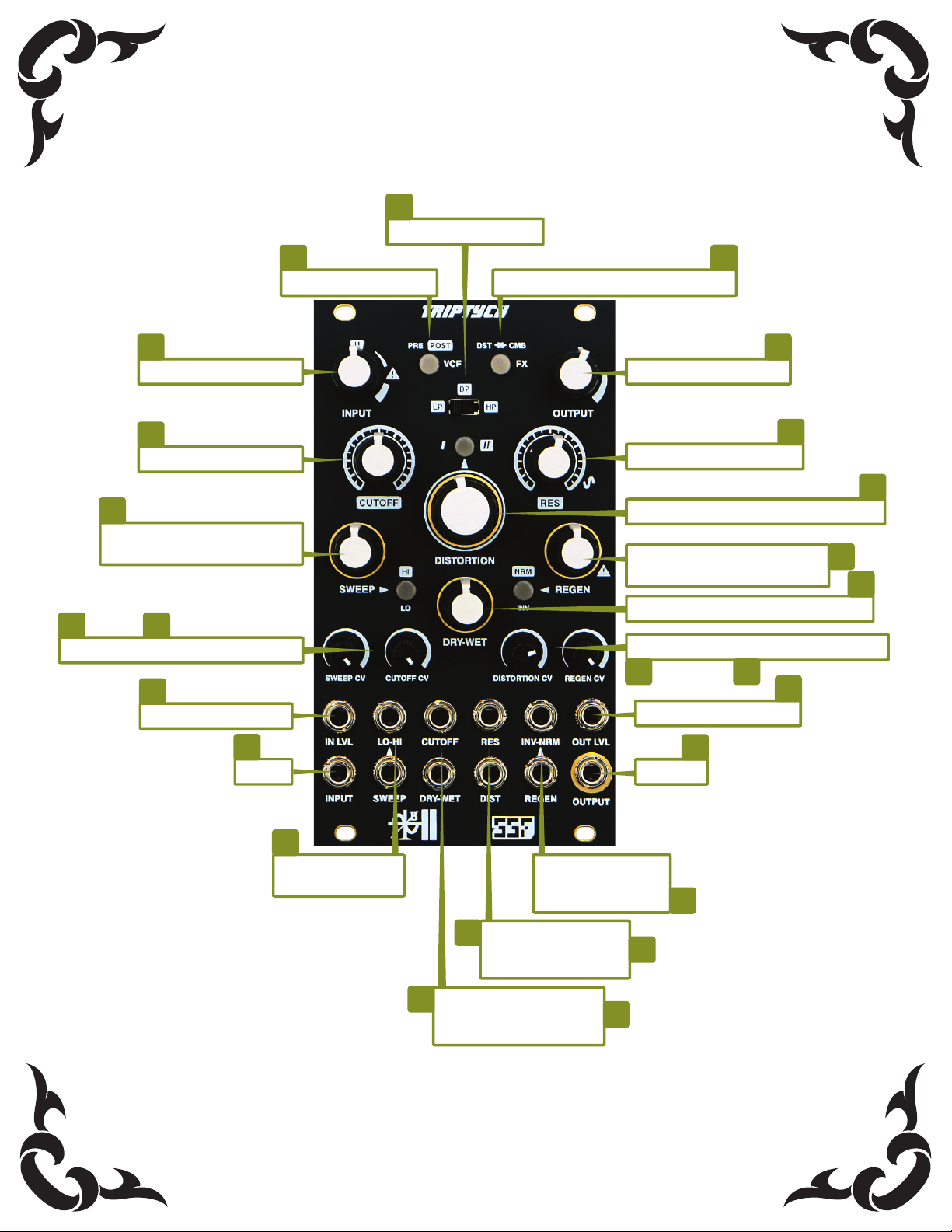
Input Level Control
VCF Route Button DISTORTION/COMB Route Button
Output Level Control
VCF Resonance Control
VCF Cuto Control
Distortion Control and Mode Button
VCF Type Select
Flange/Comb Regeneration
and Feedback Type Button
Flange/Comb DRY-WET Cross-fader
Distortion and Regen CV Attenuators
Output VCA CV Input
Output
Regeneration and
Feedback Type
CV Inputs
VCF Resonance and
Distortion Level
CV Inputs
VCF Cuto and
Flange/Comb DRY-WET
CV Inputs
Flange/Comb Clock Sweep
and Clock Range Button
Sweep and Cuto CV Attenuators
Clock Sweep and
Range CV Inputs
Input VCA CV Input
Input
1
1
2
1
2
2
2
2
2
2
3
3
3
4
4
4
4
4
4
4
4
5
6
6
6
2

FUNCTIONS
1INPUT VCA
The INPUT jack, INPUT potentiometer, and IN LVL CV jack make up the Input VCA.
Patch a signal into the INPUT to process the audio through the Triptych. Adjust the gain or attenuation via the
INPUT control potentiometer. A decent amount of gain with soft saturation is available to overdrive the VCF,
Distortion and FX sections, depending on your routing conguration. The center tick marked U denotes approxi-
mate unity input gain, with a fair presence of transistor saturation applied. Furthermore, due to the additional
gain staging via the distortion and output sections, the INPUT control will govern the overall depth of these
subsequent stages and relevant extremities. If you seek a mild distortion eect or no input saturation, set the
INPUT gain below Uand use the distortion and output sections to tailor the output levels. Distortion type has an
eect on these set points, so keep that in mind.
The INPUT level can be voltage controlled via modulation sources from 5V to 10V in amplitude.
Patch a control voltage into the IN LVL jack and use the INPUT potentiometer to adjust the overall gain. Modu-
lating the INPUT VCA can oer dramatic eects and variations through the Triptych.
2VOLTAGE CONTROLLED MULTI-MODE FILTER
The VCF is the rst major component of the Triptych. The lter slope is -12dB per octave.
Low-pass, Band-pass, and High-pass lter topologies can be selected via the LP/BP/HP switch located in the upper
middle of the module.
CUTOFF controls the cuto frequency of the lter.
RES controls the resonance amount up to self oscillation, denoted by the sine wave symbol.
CV inputs are provided for CUTOFF and RES, with the addition of a CV attenuator for the CUTOFF amount.
The VCF will track 1V per octave when the CUTOFF CV attenuator is set to maximum level.
The VCF’s position in the signal path may be altered via the VCF PRE/POST Button. When PRE is selected, the button LED will be
o and the VCF position will be set after the INPUT VCA and before the remaining sections of the Triptych. When POST is selected, the
button LED will be on and the VCF position will be set to last in the signal path, immediately before the OUTPUT VCA.
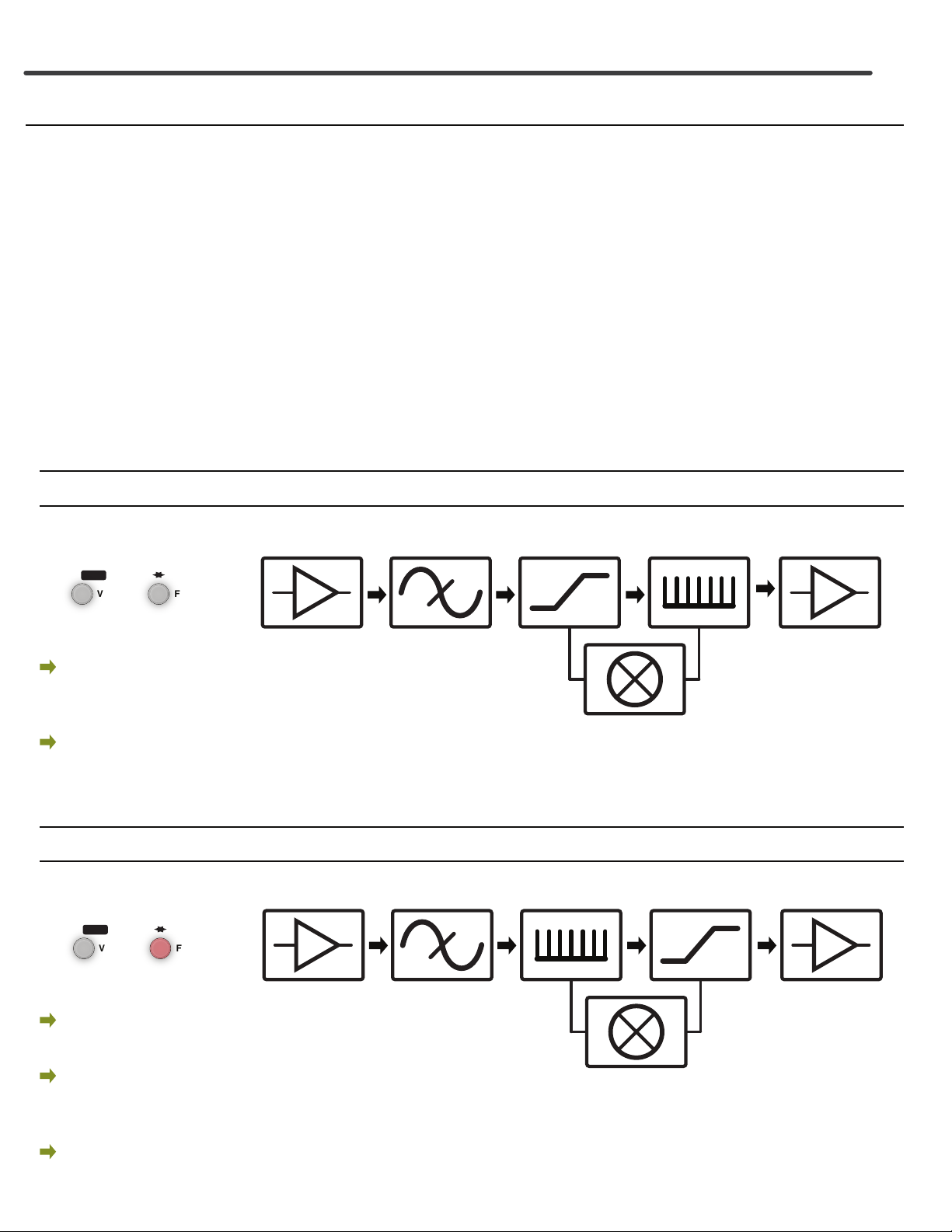
3VOLTAGE CONTROLLED DISTORTION
The VCD is the second major component of the Triptych. This section features two unique distortion
modes. As mentioned previously, the INPUT section will govern the overall available depth of the distortion
eects and should be used accordingly along with the DISTORTION control potentiometer.
Immediately above the DISTORTION control is the Distortion Mode button. This toggles between Type I
(LED o) and Type II (LED on). Both types oer soft clipping and gain at modest settings. When driven more
aggressively via the INPUT level and DISTORTION control, the two types will exhibit the following behavior:
Type I - Fold and Clip: The input waveform becomes saturated before folding sharply inward upon itself. The gain
of the unfolded portions then increase at a high rate and become hard clipped with slightly peaking rising and falling edges
(depends on the symmetry of the input waveform). See APPENDIX for a visual.
Type II - Re-Fractal Fold and Clip: The input waveform becomes saturated before folding mildly inward upon
itself. A sharp refractory peak quickly develops and bursts in the opposite direction. The overall gain of the waveform then
increase at a high rate and becomes hard clipped with peaking rising and falling edges (depends on the symmetry of the
input waveform). This type results in an overall higher amplitude output. See APPENDIX for a visual.
3

FUNCTIONS continued
4VOLTAGE CONTROLLED FLANGE-COMB
The nal component of the Triptych and the most expressive and potentially destructive of the three.
Eects range from fast delays to anging and comb ltering. This is a resonant eect and can be very aggressive,
especially when processed through the Distortion section. While most BBD eects employ a simple low-pass
lter in the feedback loop to mitigate noise and reduce the clock feed-through, this design intentionally allows
higher frequency material, including clock noise to pass into the feedback (REGEN) VCA. In fact, a slightly reso-
nant eect is applied before feedback (REGEN) with the intention of enhancing edgier, high frequency content
to pass back to the input, resulting in more characterful and potentially extreme eects.
SWEEP controls the clock speed of the analog BBD, the device responsible for producing the
Flange-Comb eect. The corresponding LO/HI button toggles the frequency range of the clocking oscillator.
When the LO setting is engaged (LED o), scanning the SWEEP potentiometer from min to max produces a fast
delay that evolves into anging and ends in some comb ltering. The HI setting (LED on) begins with anging
and quickly covers a broader range of comb ltering. LO/HI switching can also be voltage controlled with any
signal surpassing 1.2V and up to a frequency of about 1 kHz.
SWEEP can be voltage controlled via the SWEEP jack and associated SWEEP CV attenuator.
REGEN controls the amount of feedback into the BBD and can be pushed into self oscillation. Two types
of Regeneration feedback are selected via the associated INV/NRM Button. INV (inverted) is selected when the
LED is o, NRM (normal) is selected when the LED is on. Each of the feedback types exhibit a unique sound
prole and aect the signal in unique ways . INV/NRM switching can also be voltage controlled with any signal
surpassing 1.2V and up to a frequency of about 1 kHz.
REGEN can be voltage controlled via the REGEN jack and associated REGEN CV attenuator.
DRY-WET controls the mix between the Flange-Comb section and the previous sections of the Triptych,
depending on the current routing conguration. It is possible to completely bypass the Flange-Comb by turning
this control to the minimum setting.
The DRY-WET cross-fader may be voltage controlled via the DRY-WET jack.
5DISTORTION/COMB ROUTE BUTTON
This button governs the signal path order between the DISTORTION and FLANGE-COMB sections. The
distortion is routed into the Flange-Comb section when the LED is o, The Flange-Comb is routed into the
Distortion when the LED is on. The latter option is by far the most destructive and at times chaotic but will be
tamed at modest settings with pure annihilation possible at the extremes. The position of the VCF will either
precede the DST/CMB sections or follow them, depending on the selected VCF routing option (detailed in the
ROUTING SCHEMES section).
6OUTPUT VCA
The OUTPUT jack, OUTPUT potentiometer, and OUT LVL CV jack make up the Output VCA.
Sounds leave the Triptych from the OUTPUT jack. Adjust the gain or attenuation via the OUTPUT control potenti-
ometer. A fair amount of gain is available so expect a hot signal if input and distortion levels are near maximum.
Output can exceed 23V peak to peak, which will happily overdrive (or clip) anything you patch down the line.
The OUTPUT level can also be voltage controlled via modulation sources from 5-10V in amplitude. Maxi-
mum level is attained with 8-10V, typically from an envelope generator but LFOs also work well.
Patch a control voltage into the OUT LVL jack and use the OUTPUT potentiometer to adjust the signal level.
4
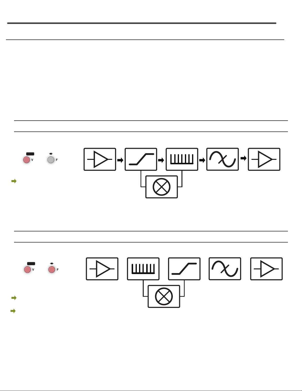
SIGNAL PATH ROUTING SCHEMES
MMVCF DISTORTIONCOMBVCA
WET-DRY
VCA
MMVCF DISTORTION COMBVCA
WET-DRY
VCA
PRE POST
VCF
DST CMB
FX
PRE POST
VCF
DST CMB
FX
Button State Signal Path
PRE-FILTER ROUTING MODES:
The following two schemes involve the Multi-Mode VCF section immediately following the Input VCA.
In general, this conguration is suited for but not limited to input signals involving a higher order of harmonic
content. For instance, if the input is a square wave, the distortion section will merely add gain without
wave-folding the signal. The VCF can round o the edges of the square waveform thereby allowing the distor-
tion circuitry to work to it’s full potential. Very dynamic distortion eects can be realized by varying Cuto,
Resonance and distortion levels when processing square waves and more complex signals such as a drum track
or individual percussion sounds. That being said, experimentation with all signal types is encouraged and can
also produce interesting results.
The Pre-Filter routing schemes may also reveal the unbridled BBD clock noise and feedback, most nota-
bly with particular Cuto settings and even more so when the Distortion follows the FLANGE/COMB. If this
noise is not desired, try using CV’s for the Output VCA, DRY-WET control or both controls to govern the noise,
dynamically.
Graphical representations of the Pre-Filter Signal Paths along with the associated button states are
shown below. General notes for each mode are provided for reference.
Great for, but not limited to signals with high or complex harmonic content.
Use with drum tracks or individual percussion
Use with square waves, complex drones, full mixes etc.
Can be noisy with particular VCF settings and/or less harmonically dense input signals.
Use DRY-WET controls and/or DRY-WET and Output VCA
CV to dynamically control noise if not desired.
Button State Signal Path
Most destructive and chaotic mode due to the nature of processing a BBD through the Distortion.
Higher Input and Distortion levels may be needed to enhance these effects.
Great for, but not limited to signals with high or complex harmonic content.
Use with drum tracks or individual percussion
Use with square waves, complex drones, full mixes etc.
Can be noisy with particular VCF settings and/or less harmonically dense input signals.
Use DRY-WET controls and/or DRY-WET and Output VCA
CV to dynamically control noise if not desired.
5
MMVCF
DISTORTIONCOMBVCA
WET-DRY
VCA
MMVCF
DISTORTION COMB
VCA
WET-DRY
VCA
SIGNAL PATH ROUTING SCHEMES cont..
PRE POST
VCF
DST CMB
FX
PRE POST
VCF
DST CMB
FX
POST-FILTER ROUTING MODES:
The nal two schemes involve the Multi-Mode VCF section placed immediately before the Output VCA,
after the Distortion and Flange/Comb sections. In general, these congurations are suited for all signal types.
Placing the VCF last in the chain allows for greater control over the frequency content and overall ability
to ‘carve out’ the sound. The wave-folding Distortion and Flange/Comb add harmonic content while the VCF
removes or isolates those harmonics. These routing congurations are great for setting up a dirty acid VCF and
shaping karplus strong eects from the BBD section.
Graphical representations of the Post-Filter Signal Paths along with the associated button states are
shown below. General notes for each mode are provided for reference.
Button State Signal Path
Generally great for signals of all types.
Most‘standard’configuration.
Create a very characterful VCF
Add harmonics to simple waveforms - like sine and triangle waves
Great on drums , full mixes etc.
Dirty acid machine #1
Button State Signal Path
Most destructive and chaotic -can be tamed using the VCF last in the chain
Generally great for signals of all types. Although signals with sharp transients
produce the best effects through the BBD section. A fast envelope into the
Input VCA CV can impart this characteristic onto any signal.
Create a very characterful VCF
Add harmonics to simple waveforms - like sine and triangle waves
Great on drums , full mixes etc.
Dirty acid machine #2
6

APPENDIX
DISTORTION WAVEFORM EXAMPLES:
TRIANGLE WAVE input shown with INPUT set @ U and increasing DISTORTION and INPUT levels
TYPE I TYPE II
7

PATCH EXAMPLES COMING SOON...
Table of contents


