manuals.online logo
Brands
  1. Home
  2. •
  3. Brands
  4. •
  5. SSHC
  6. •
  7. Controllers
  8. •
  9. SSHC TSSHC-3IL-24 User manual

SSHC TSSHC-3IL-24 User manual

©SSHC, Inc. All Rights Reserved 4 Custom Drive, PO Box 769, Old Saybrook, CT 06475 (800)544-5182 (860)399-5434 (860)399-6460(fax)
MAXIMUM COMFORT AND CONTROL IN HEATING
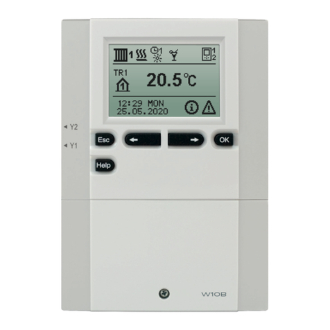
TSSHC-3IL-24 is an electronic heading thermostat designed to be
installed in a standard single gang electrical box with a minimum
width of 2-1/4". Once installed, it requires no maintenance.
An LED illuminates to indicate “call” for heating, this also aids in
system testing. An ON/OFF selector switch
on the front of the cover makes system operation extremely simple.
CE MARKING
This product meets the requirements of the European Council's
directive 89/336 and successive modifications as to electro-magnetic
compability and the Council directive 73/23 as to electrical equipment
to be applied within certain voltage ranges.
Standards applied
En 50 081 -1, EN 61000-6-2, and EN 60730-2-9.
If the product has been exposed to damage e.g. in transport, it must as
checked and overhauled by qualified staff before the product is
powered up.
CLASSIFICATION
The product is a class III device according to IEC 60730-2-9 and EN W730-2-9 and the product must be
connected to the following conductors:
1) L-24V AC
2) N - 0 (neutral)
WARNING
The system may not be energized unless the system is installed according to this instruction and the
installation meets all applicable codes. Warranty is void if not installed according to this instruction and proper
procedure.
TECHNICAL DATA
Power supply …………………….24V AC +/-10%, 60 Hz
Output relay, SPST, dry contact………………………..2A
Built-in switch………………………………………….2 pole
ambient operating
temperature……………………………..32-122 F (0-50 C)
Scale limitation……………………minimum and maximum
Scale range……………………………..40-104 F (5-40 C)
Temperature setback………………………….not available
On/Off differential…………………………….0.7 F (0.4 C)
Enclosure is………………………………………………IP20
Dimensions (HxWxD)………………………..4.5"x3.3"x2.0"
…………………………….…(115x84x50 mm)
SSHC, INC.
ENERJOY RADIANT PEOPLEHEATER®TSSHC-3IL-24
PRODUCT LINE
TSSHC-3IL °F
24V ( -24 )
TSSHC-3IL-24FSF UDF with floor sensor
TSSHC-3IL-24 UDF with built-in sensor
TSSHC-3IL °C
24 V supply
TSSHC-3IL-24CFS UDC with floor sensor
TSSHC-3IL-24C UDC with built-in sensor
©SSHC, Inc. All Rights Reserved 4 Custom Drive, PO Box 769, Old Saybrook, CT 06475 (800)544-5182 (860)399-5434 (860)399-6460(fax)
FLOOR SENSOR INSTALLATION (where applicable)
The sensor shall be mounted in a conduit which should be sealed and
placed as high as possible in the concrete, etc. The sensor is UL and
cUL approved regarding the isolation test. The sensor wiring may be
extended up to 150' (50 m) using 18 gauge wire and the wiring
resistance shall not exceed 20 ohms. Sensor wires must be kept in a
separate conduit, away from all other wiring. The sensor and wires
must be protected from damage during the installation. If shielded
wire is used, it must not be grounded but connected to terminal 6 on
the thermostat.
ERROR DETECTION (floor sensor model only)
The TSSHC-3IL-24 has built-in error detection which will
de-energize the heating circuit if the sensor is damaged or if it detects
an open or shorted sensor circuit.
CAUTION!
Disconnect all electrical power prior to installing or servicing this
unit.
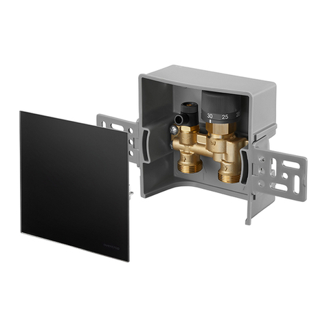
THERMOSTAT INSTALLATION (fig. 1 2)
1. Remove thermostat knob, noting the position (A).
2. Loosen screw to remove frame and cover (B).
3. Attach wiring from the rear of the thermostat according to the
wiring diagram.
4. The thermostat is mounted in a standard single gang electrical box
with a minimum width of 2-1/4”.
- re-install frame and over
- re-install the knob in the proper position
TEMPERATURE SETTING/ADJUSTMENT
Adjust the temperature knob to the desired room or floor temperature,
if after a few days you find the temperature to be different from the
setting, adjustment can be made as follows: Measure the room
temperature with thermometer, remove the knob without rotating it,
then reposition the knob according to the measured temperature on the
scale and re-install it.
MAXIMUM/MINIMUM TEMPERATURE LIMITATIONS
Behind the knob them are red and blue locking rings hold in position
by a screw. To set the limitations, loosen the screw (C) and adjust the
red limit ring to the desired maximum, sat the blue ring to the desired
minimum temperature, then retighten the screw. The knob must be re-installed exactly as it was removed.

Popular Controllers manuals by other brands

ActronAir LC7 Operation manual

ActronAir

ActronAir LC7 Operation manual

Ascon tecnologic K32 Engineering manual

Ascon tecnologic

Ascon tecnologic K32 Engineering manual

Ruckus Wireless SmartZone 100 Administrator's guide

Ruckus Wireless

Ruckus Wireless SmartZone 100 Administrator's guide

Siemens SINUMERIK MCU1720 Equipment manual

Siemens

Siemens SINUMERIK MCU1720 Equipment manual

Johnson Controls Metasys FAC4911 installation guide

Johnson Controls

Johnson Controls Metasys FAC4911 installation guide

Norac UC4+ Roll Control installation manual

Norac

Norac UC4+ Roll Control installation manual

White Rodgers 668 installation instructions

White Rodgers

White Rodgers 668 installation instructions

AMX AXB-PT10 manual

AMX

AMX AXB-PT10 manual

KDE Direct LV Series instruction manual

KDE Direct

KDE Direct LV Series instruction manual

Adaptec ASR-5085 Information sheet

Adaptec

Adaptec ASR-5085 Information sheet

Siemens SQK349.00/209 Mounting instructions

Siemens

Siemens SQK349.00/209 Mounting instructions

DoorKing 4302 owner's manual

DoorKing

DoorKing 4302 owner's manual

Verasys LC-VAC3000-0 quick start guide

Verasys

Verasys LC-VAC3000-0 quick start guide

YASKAWA YRC1000 Startup guide

YASKAWA

YASKAWA YRC1000 Startup guide

Crestron CNECI-4A Operation guide

Crestron

Crestron CNECI-4A Operation guide

HANYOUNG NUX HY Series instruction manual

HANYOUNG NUX

HANYOUNG NUX HY Series instruction manual

V2 AYROS1500-I manual

V2

V2 AYROS1500-I manual

SSV Works BMC Installation and user guide

SSV Works

SSV Works BMC Installation and user guide

manuals.online logo
manuals.online logoBrands
  • About & Mission
  • Contact us
  • Privacy Policy
  • Terms and Conditions

Copyright 2025 Manuals.Online. All Rights Reserved.