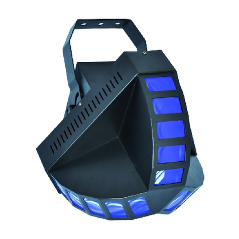
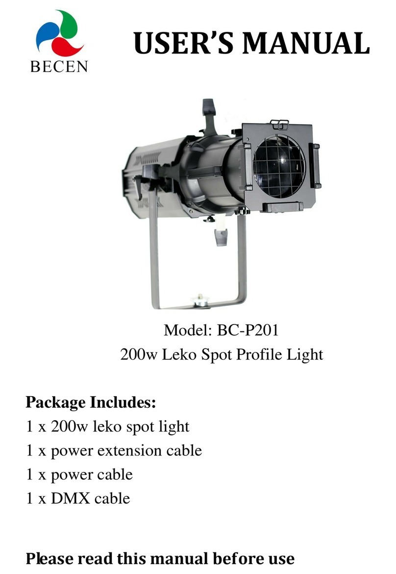
SSI METEORLITE User manual

STROBE LIGHT
WARRANTY AND INSTALLATION
INSTRUCTIONS
FIVE YEAR WARRANTY
This light is warranted against defects in materials and workmanship for
ve years from the date of purchase. Should service be required, the light
will either be repaired or replaced as covered by this warranty. Customer
should return product for warranty consideration. Shipping will be prepaid
via ground transportation by consumer. All products requiring warranty
service shall be returned within ve years from the date of purchase. Exclu-
sions from this warranty include the product nish and damage caused by
improper installation.
The manufacturer assumes no liability for costs incurred in removing
or reinstalling products requiring service.
This warranty gives you specic legal rights. You may also have other
rights which vary from state to state and country to country.
EL510-2250
INSTALLATION INSTRUCTIONS
®
16355 SOUTH LONE ELM ROAD
OLATHE, KANSAS 66062 • USA
TOLL FREE: 800-447-3693 • PHONE: 913-780-1440 • FAX: 913-780-1427
www.superiorsignals.com
Maintenance:
• Normal cleaning of the dome/lens can be done using mild soap and a soft
cloth. (Do not use cleaning agents such as solvents or petroleum products,
these can damage the lens).
• Should the lens become scratched or hazy, this can normally be removed by
using a non-abrasive quality automotive paste cleaner-wax, or plastic polish.
Replacement LED Light Towers:
Class I P/N’s: Amber LED Lamp SY22050-TWR2-A
Blue LED Lamp SY22050-TWR2-B
Red LED Lamp SY22050-TWR2-R
EA13 P/N’s: Amber LED Lamp SY22050-TWR3-A
Replacing LED Lamp Towers:
1. Disconnect the two LED Lamp wire connectors from the strobe base.
2. Remove (3) #6 screws (located at the base of the flash tube) and remove
by lifting straight up.
3. Note LED Lamp orientation and replace with new Lamp in original location
as shown in figure below.
4. Reconnect the two wire connectors from the new LED Lamp to the strobe
base.

• Carefully route power cable from the strobe to power supply. Make sure to fuse
the positive wire within 10 inches from the power source (5AMP fuse min.)
Note - Any two of these series strobes can also be setup to flash together (syn-
chronized) or alternately. To setup two units to synchronized flash, connect the
purple wires from the two units together. To setup two units to flash alternately,
connect the purple wires from the two units together and connect one of the yellow
wires to the (black) ground wire. (The yellow wire on the other unit is not needed
and should be secured out of the way).
Flash Pattern Selection (Optional):
This MeteorLite LED Strobe Beacon has 11 available flash patterns. Pattern selection
is optional and should be performed during the installation procedure. The product is
preset from the factory with flash pattern #1, if this pattern is acceptable no further
action is required. If you desire another pattern, proceed with the steps below.
1. Locate the program selection (yellow) wire.
2. Power on unit by connecting the red wire to positive and the black wire to
negative on a (12-48 VDC) power source.
3. The strobe light should now be on and flashing. With the unit on, momen-
tarily connect (or touch) the yellow wire to the black wire to enter program
mode. Once in program mode, each time these two wires are connected,
the flash pattern will change. Continue until the desired pattern is active.
The Strobe will now flash in this pattern when it is turned Off and On.
See chart below for a list of the available patterns.
Pattern Description Flash Rate
1 Quad Flash 80 FPM
2 Rapid Flash 120 FPM
3 Double Flash 80 FPM
4 Single Slow Flash 60 FPM
5 Quint Flash 80 FPM
6 Accelerated Flash 60 FPM
7 Single Flash 80 FPM
8 Double Slow Flash 60 FPM
9 Triple Flash 80 FPM
* 10 Random Flash #1 NA
** 11 Random Flash #2 NA
* This pattern runs through 1 cycle of each of the above flash patterns (1-9) randomly
** This pattern runs through 5 cycles of each of the above flash patterns (1-9) randomly
Magnetic Mount Instructions:
• Clean mounting surface and magnets to ensure they are free of foreign
particles
• Place strobe light on the vehicle on a clean, level, flat, steel surface in the
desired location.
• Route cord with plug to the power receptacle (cigarette lighter socket) of the
vehicle.
INSTALLATION INSTRUCTIONS INSTALLATION INSTRUCTIONS
Installation Instructions:
This strobe light is completely wired at the factory and does not require any additional
internal wiring.
• The light must be connected to 12-48VDC power source.
• Use 16AWG (minimum) wire to connect the light to the power source.
(Check that red wire is connected to positive and the black wire is
connected to negative.)
• If using a power convertor to meet 12VDC requirements, convertor must
be rated for min. - 5AMPS.
Permanent Mount Instructions:
• Check to make sure that no vehicle components will interfere with the
selected mounting location of this unit.
• Position the light in a relatively flat, level position in the proposed mounting
location. Mark mounting hole and wire routing hole.
• Drill mounting holes, Also, if required drill wire routing hole.
• Mount light using appropriate hardware.
• Install grommet into the wire routing hole, and connect the red/positive
wire to power, and the black/negative wire to ground.
(Note: It is recommended to apply sealing compound around the area where the
wires pass through the mounting surface, to prevent any possible leaking.)
WARNING!
Electrical/Electronic Device – Potential Shock Hazard
Table of contents


