SSR Motorsports SR450S User manual
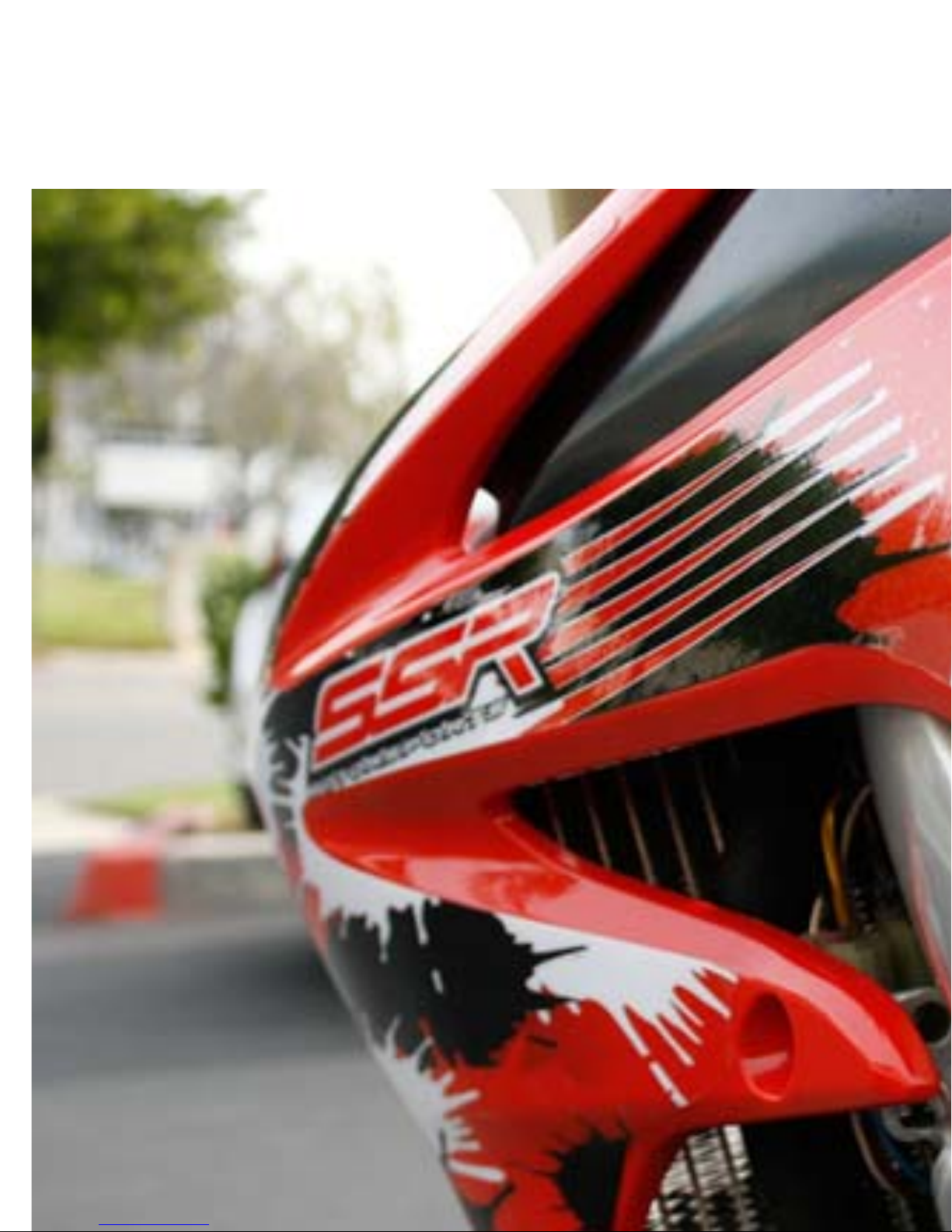
SR450S
IMPORTANT
YourSSRMotorsportsMotorcyclewillbringyoumuchpleasureifyou
followthepropermaintenanceandcareinstructions.
Bewarethoughalltheinformationinthisdocumentareprovided
withoutanyobligation.Subjecttochange,deletionorsubstitution
withoutadaptationtolocalrequirementsintechnicalinformation,
pricing,andproductionofafinaljudgmentofaparticularmodel
withoutpriornoticeorindicationofanyreasonbySSRMotorsports.

Maintenance
Compliancewithmaintenance,maintenanceandadjustmentoftheengineandchassis‐
partscontainedinthismanualisaprerequisitefortheproperfunctioningofthebikeand
helpstoavoidprematurewear.Impropermaintenanceofthecyclepartcouldresultin
damageorfailureofcomponents.Useofthemotorcycleunderextremeconditions,such
asonslopes,verymuddyorwetterrain,mayleadtoexcessivewearofcomponentssuch
aschainorbrakes.
Alsoobservetherunning‐inperiodandthecontrolandmaintenanceintervals,proper
maintenancecansignificantlyprolongthelifeofthemotorcycle.
Warranty
Thewarrantyperiodis90daysonEngine/Transmission(PartsOnly),30daysLimited
VehicleWarranty(PartsOnly),90daysLimitedBatteryWarranty.
Onlywhennotusedforcompetition.
Theworkplannedintheserviceschedulemustalwaysbeperformedbyanauthorized
dealerandallworkmustberecordedintheservicebookorabillwiththechassisserial
number.Ifapplicable,thewarrantyisvoid.Thewarrantymaybevoidandunsupported
fordamagesandconsequencesresultingfrommanipulationsand/orchangestothe
vehicle.

Transport
Riskofdamageifthevehicleisparkedonaslope,itmayrollawayorfallover.
Alwaysparkthevehicleonafirmlevelfloor.
Note
•Riskoffireduringoperationifthevehiclepartsbecomeveryhot.
•Donotparkthemotorcyclenearflammableorcombustiblematerials.Donotplace
objectsonthemotorcyclewhenitishot.
Alwayswaituntilthemotorcyclehascooled.
•Stoptheengine.
•TurnthefueltaptoOFF.
Environment
Thissportcanhavepotentialimpactsontheenvironmentandcauseconflictwithothers.
Responsibleuseofthebikeallowsriderstoavoidproblemsandconflicts.Inordernotto
jeopardizethefutureofmotorcyclesport,makesurethattheuseofthemotorcycle
complieswiththelawandrespectstheenvironmentandtherightsofothers.

Technical Specification
I
TE
M
TE
C
H
NI C
A
L
D
A
T A
O
F
FR O
A
D
MO
TA
R
D
D
I
ME
N
S
I
ON
S
O
V
E
R
A
L
L
L
E
N
G
T H
2
1
7
5
m m
O
V
E
R
A
L
L
WI D
T H
8
1
0
m m
O
V
E
R
A
L
L
H
EI G
H
T
1
2
4
0
m m
F
/ R
W H
E
E
L
A
XI
S
D
I
S
TA
N
C
E
1
5
0
5
m m
S
E
A
T
H
E
I
G
H
T
9
6
0
m m
G
R
O
UN
D
C
L
E
A
R
AN
C
E
3
2
0
m m
N
. W
1
1
8
k
g
1
3
0
k
g
C
H
A
S
S
I S
F
R
A
M E T Y
P
E
A
L
U
MI N
IU
M
A
L
L
O Y
TWI N
-
S
P
A R
F
R
ON
T
TI R
E
S
IZ
E
8
0
/
1
0
0
-
2
1
1
1
0
/
7
0
-
1
7
R
E
A
R
TIR
E
SI Z
E
1
1
0
/
9
0
-
1
9
’
’
1
4
0
/
7
0
-
1
7
F
R
ON
T
S
U
S
P
E
N
SI O
N I
N
V
E
R
TE
D
C
AR
TR ID G
E
F
O
R
K
WI
TH
R
E
-
B
O
U
N
D
C
O
MP
R
E
S
SI O
N
-D
A
MP
I
N
G
A
DJ U
S
T
R
E
A
R
SU
S
P
E
N
SI O
N
MO
N
O
S
H
O
C
K
WI
TH
S
P
RI N
G-
P
R
E
L
O
A
D ,
R
E
- B
O
U
N
D
A
N D
C
O
MP
R
E
S
S
I
ON
-
D
A
MP
IN
G
AD
J
U
S
T
F
U
E
L
TA
N
K
C
A
P
AC
I TY
8
.
0
L
WI
TH
R
E
S
E
R
V
E
V
A
L
V
E
MOTEUR
TY
P E S I N G L E
CY
LINDER, 4-STROKE, LIQUID COOLED
MA
X P O W E R
3
2
K
W / 7
5
0
0
R
P
M :
4
3. 5
H
P/ 7
5
0
0
R
P
M
RATED POWER
3
0
.
5
K
W / 7
0
0
0R
P
M
COUPLE MAX
4
2
.
5
N
M/ 6
5
0
0
R
P
M
IDLE SPEED 1700±150 RPM
CONSOMMATION ≤340 g/kW.h
BORE X STROKE 96×62.1 mm
DISPLACEMENT 449 ml
COMPRESSION RATIO 11:1
VALVE TRAIN CHAIN DRIVE SOHC FOUR VALVE
LUBRICATION
TY
PE PRESSURE SPRAY
LUBRICATION OIL
TY
P E SAE 10W-40
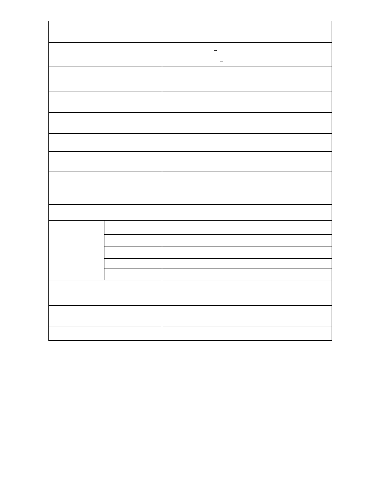
IGNITION ADVANCE DEGREE 12°BTDC [3000RPM]
VALVE CLEARANCE (COLD) INTAKE VALVE: 0.16+0.03 mm
EXHAUST VALVE: 0.28+0.03 mm
DECOMPRESS
CLEARANCE EX VALVE CLEARANCE (0.28mm)+0.15mm=0.43mm
SPARK PLUG
TY
PE DENSO IK24/IK27
DIMENSION
350mm
×
297mm
×
423
mm
DRIVE
TY
P E C H A I N
DRIVE SPROCKET
1
3
T
CLUTCH
TY
P E MANU AL, MU LTI -WET
TRANSMISSION
TY
PE CONSTANT MESH, 5 SPEED,
LEFT
FOOT OPERATED
PRIMARY ADJUCTION RATIO 2.739(63/23)
GEAR RATIO
1ST 2.230(29/13);
2ND 1.625(26/16)
3RD 1.235(21/17)
4TH 1.000(19/19)
5TH 0.826(19/23)
IGNITION
TY
PE DC/AC CDI
STARTER KICK / ELECTRIC
STARTING CAPACITY ≤15 s

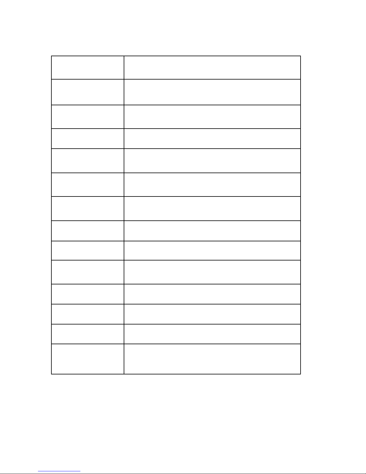
Lubrication system
I
TE
M
D
A
T A
E
N
G
I
N
E
O
I L
8
7
0
m
l
A
P
I
S
G
o
r
h
i
g
h
e
r
S
AE
1
0
W-4
0
A
T
D
R
A
IN IN
G
6
7
0
m
l
A
T
F
I
L
TE
R
C
H
AN
G
E
7
0
0
m
l
A
T
D
I
S
A
S
S
E
MB
L
Y
8
7
0
m
l
TR A
N
S
MI S
S
I
O
N
O
I L
9
5
0
m
l
API SG or higher
S
A
E 1
0
W
-4
0
A
T
D
R
A
IN IN
G
8
5
0
m
l
A
T
D
I
S
A
S
S
E
MB
L
Y
9
0
0
m
l
(Approximately O
n
e
Q
u
a
r
t )
ATTENTION: Low Oil level in Tr a n s m i s s i o n can cause transmission
failure. Warranty Void if transmission oil is not kept at mandatory level.
Failure to change transmission oil and oil filter on scheduled maintenance
and at recommended level of 950ml can cause the transmission to lock and
cause serious injury or death
I
TE
M
D
A
TA
C
O
O
L
A
N
T
C
A
P
AC
I TY
A
T
C
H
A
N G
E
1
.
1
1
li
t
e
r
D
I
S
A
S
S
E
MB
L
Y
1
.
2
0
l
i
t
e
r
A
N
TI FR E
E
Z
E
H
I
G
H
Q
U
A
LI
TY
E
T H Y
L
E
N
E
G
L Y
C
O
L
A
N
TIF R
E
EZ
E C
O
N
TA
I
NI N
G
S
I
LI C
A
TE
-
FR E
E
C
O
RR O
S
I O N I
N
-
H
I
B
I
TO
R
S
S
TA
N
D
A
R
D
S
C
O
O
L
AN
T
C
ON
C
EN
TR A
-
TI O
N
1
: 1
MI XTU R
E
WI
TH
D
I
STI LL
ED
W A
TE
R

Tire Specifications
I
TE
M
S
TA
N
D
A
R
D
S
R
E
P
A
I R
L
I
MI
T
C
O
L
D
TIR
E
PR
E
S
S
UR
E
3
3
/
2
. 3
(
ps
i
/
b
a
r
)
MA X
L
O
A
D
F
R
ON
T
4
3
0 /
1
9
5
(
l
b
s/ k
gs
)
R
E
A
R
5
4
8 /
2
6
5
(
l
b
s/ k
gs
)
Battery specifications
I
TE
M
D
A
T A
B
A
TTE
R
Y
C
A
P
A
C
I TY
1
2
V
-
6
A
h
C
UR R
E
N
T
C
ON S U MPTIO
NM
A
X
0
.
1
m
A
V
O
L
TA
G
E
(
2
0
0
/
6
8
0
F
)
F
U
L
L
1
3
.
0
-
1
3
.
2
V
Spark plug specifications
I
TE
M
D
A
T A
S
P
A
R
K
P
L
U
G
S
TA
N
D
A
R
D
S
D
E
N
S
O I
K
2
4
O
P
TI O
N
A
L
N
G
K I
FR 8
H
-
1
1
INSPECTION BEFORE USE
Inspection Item
Inspection Objective
Engine oil Inspect for
proper
f i l l
lev
el
Gearbox oil Inspect for proper level (900ml)
Coolant Inspect for
proper
f i l l
lev
el
Fuel Be sure there is
enough
fuel to ride planned distance
Cooling system Inspect for leaks, cracks,
and
fluid
f l o w
Throttle
Check for
free travel of throttle grip and that the throttle grip has a smooth
operation and in both t
he
forward and back to the closed position
Clutch Adjust the clutch cable to fully disengaged
Steering Be sure the bars
mov
e
freely from lock to lock and steering head is tight
Brake Inspect for free
trav
el of pedal and
lev
er and that there
is
full braking power
Tire Check tire pressure and inspect tires for cracks
Spokes Inspect and tighten loose spokes if necessary
Other Bolts and Parts Inspect attachment points and other bolts to ensure they are tight
Exhaust muffler
Inspect for loose bolts and the exhaust is secure

BREAK-IN
The motorcycle is shipped with break in Oil
ONLY
!
Once the engine is run for an initi
a
l 30 minutes, drain and replace the
o
il with:
Synthetic API SG or higher SAE 10W-40
Failure to do so may decrease the engine transmission life or cause premature failure.
During initial break-in newly machined surfaces will be in contact with each other and these surfaces will wear in quickly.
Break-in maintenance at 150km is designed to compensate for this initial minor wear. Timely performance of the break-in
maintenance will ensure optimumservice life and performance from the engine.
The general rules as follows:
Start the engine and let it run at idle until the engine is thoroughly warmed up.
Avoid full-throttle starts and rapid acceleration.
Maximum
continuous engine speed during the first 150km must not exceed 5,000 rpm (or 10 hours Max)
After 150km ride maintenance the machine per the maintenance schedule.
After the break-in procedure has been properly carried out, the motorcycle is
ready
for regular operation. However, since
premature high r/min (rpm) will lead to engine trouble, take care to use the necessary skill and technique in
operating
the
motorcycle.
Never run
the
engine with full throttle at low speed operation. This rule is applicable not only during break-in but at all
times.
This procedure should be followed each time:
Piston is replaced
Piston rings are replaced
Cylinder is replaced
Crankshaft or crank
bearing
are replaced

Maintenance
The Maintenance Schedule specifies how often you should have your motorcycle served, and what things need attention. It
is essential that your motorcycle be served as scheduled to retain its high level of safety,
dependability,
and emission
control performance.
Remember,
proper maintenance is your responsibility.
PR
ECAUTION
Make sure the engine is off before you begin any maintenance or repairs.
Exhaust contains poisonous carbon monoxyde. Be sure there is adequate ventilation whenever you operate the
engine. Let the engine and exhaust system cool before touching
Be ca reful when
working
around gasoline. Keep cigarettes, spark, and flames away from all fuel related parts
Regular Maintenance
Place the motorcycle on the firm level ground using optional work stand or equivalent support
Use genuine or recommend part and lubricants or other
equivalents.
Parts that do not meet design specifications may cause
damage to the motorcycle
Use only metric tools when
servicing
the
motorcycle,
metric nuts, bolts, screws are not interchangeable with British
fasteners. Always replace with new gaskets, O-rings, cotter pins, piston pin clips, snap rings, etc after disassembling the
engine.
When
tightening
bolts and nuts, begin with larger diameter or inner bolt first. Then tighten to specified torque diagonally in
incremental steps unless a particular sequence is specified.
Clean parts in
cleaning
solvent upon disassembly, lubricate and sliding surface before
assembly. Always inspect all parts for proper installation
and
operation after reassemble
Route all electrical wires, cables and harness
routing
as designed.
MAINTENANCE SCHEDULE
Required maintenance schedule is based upon average riding condition. Sustained high speed operation, or operation in
unusually wet or dusty
conditions,
will require more frequent service than specified in the REQUIRED MAINTENANCE
SCHEDULE.
See
SPECIA
L MAINTANCE SCHEDULE for competition maintenance need.
Perform the Pre-ride inspection at each scheduled maintenance period

Symbol in maintenance schedule means:
IInspect, Clean, Lubricate and/or Replace as Necessary
CClean
RReplace
AAjust
LLubricate
* Unless the rider is mechanically qualified and has proper tools, see authorized dealer for service
* * Special maintenance strongly recommend to look for authorized dealer service.
NOTE1. Clean after every ride for dusty conditions
NOTE2. Replace every 2 years. Replacement requires mechanical skill
NOTE3. Replace after the first break-in ride
NOTE4. Inspect after the first break-in ride
NOTE5. Replace the transmission oil when the clutch plates are replaced.
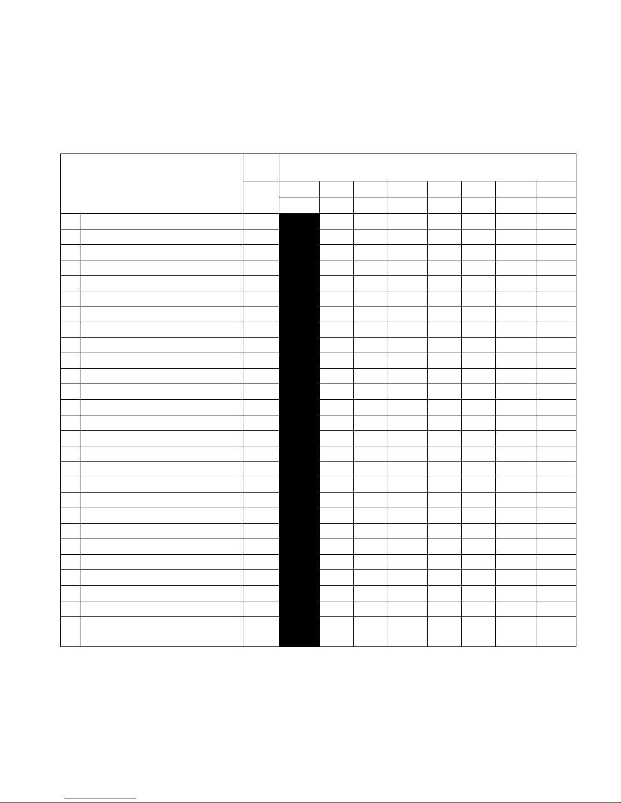
Required Maintenance Schedule
MAINTENANCE ITEMS
SCHEDULE BY HOURS OR KILOMETERS
NOTE
Hours
10 30 50 70 90 110 130
km 150
1500
3500
6000 9000 12000
15000
* ENGINE OIL R R R R R R R
* AIR FILTER R R R
GEARBOX OIL R R R R R R R
ENGINE OIL FILTER R R
RADIATOR COOLANT R R
* ENGINE VALVE CLEARANCE I I
SPARK PLUG R R
** FUEL FILTER C C
* FUEL LINE I I I I I I I
* THROTTLE ASSEMBLY I I I I I I I
COOLING SYSTEM I I I I I I I
SECONDARY AIR SUPPLY I I I I I I I
DECOMPRESSOR SYSTEM I I I I I I I
ENGINE IDLE SPEED I,L I,L I,L I,L I,L I,L I,L
DRIVE CHAIN I I I I I I I
DRIVE CHAIN SLIDER I I I I I I I
ENGINE IDLE SPEED I I I I I I I
BRAKE PAD WEAR I I I I I I I
BRAKE SYSTEM I I I I I I I
HEADLIGHT FOCUS I I I I I I I
* CLUTCH I I I I I I I
SIDE STAND I I I I I I I
* SUSPENSION I I I I I I I
MUFFLER I I I I I I I
NUTS, BOLTS, FASTENERS I I I I I I I
WHEELS/TIRES I I I I I I I
* SUSPENSION
BUSHINGS/BEARINGS I I I I I I I
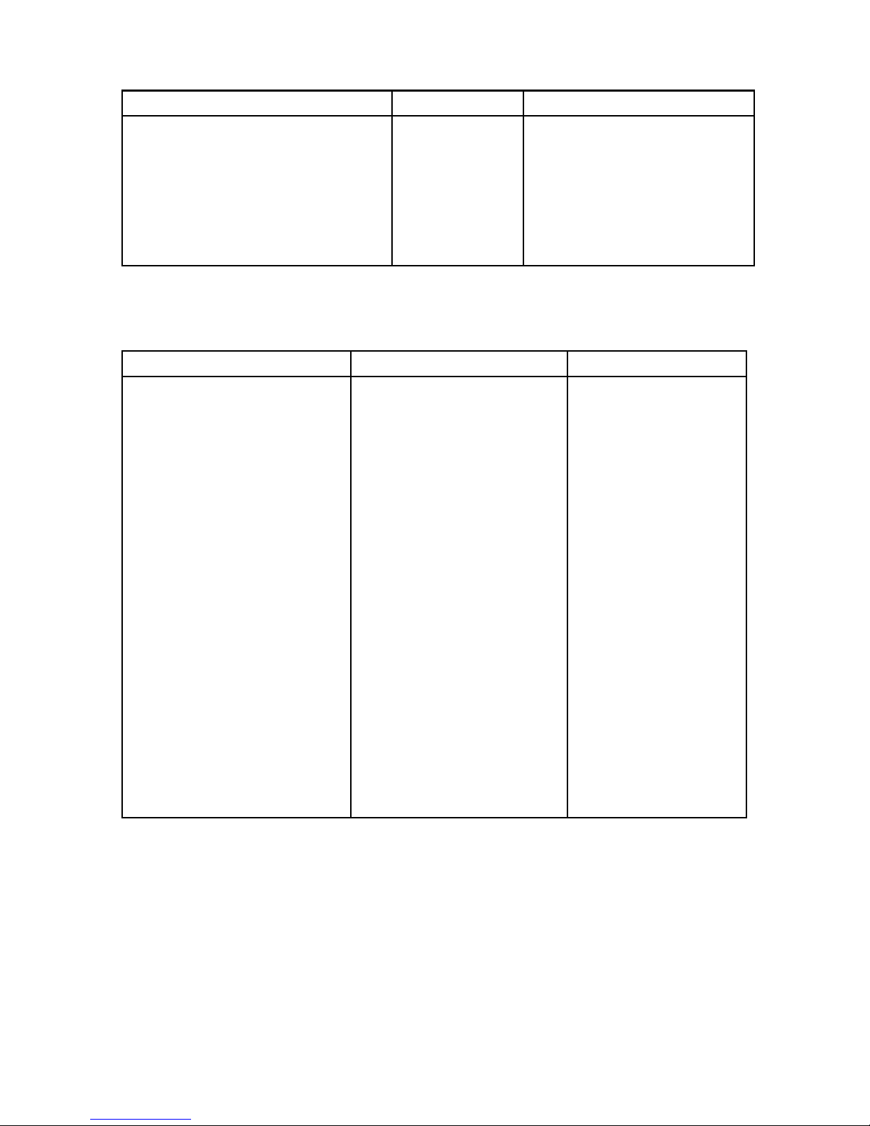
MOTOR
ITEM CAUSE REMARK
Cy
linder head gasket
Clutch disc
Cy
linder gasket
Right crankcasecover gasket
Compression leak
Wear or discoloration
Leakage
Damage
Replace
whenev
er disassembled
Replace
whenev
er disassembled
Replace
whenev
er disassembled
CHASSIS
ITEM CAUSE REMARKS
Front / rear tire
Front / rear brake pad
Sub-f
rame mountingbolts
Chain guide plate
Side
cov
er
Front number plate
Front /
rear
f ender
Clutch
lev
er / holder
Brake
lev
er
Air throttle lever
Handlebar
Throt t le hous ing
Grip rubber
Gearshif
t pedal
Brake pedal
wear
wear
Fatigue or damage
Wear or damage
Damage
Damage
Damage
Free play or damage
Free play or damage
Free play or damage
Free play or damage
Bends or cracks
Damage
Damage
Damage
Damage
Damage
Minimum knob height: 8mm
Minimum thickness:1mm
NOTE:
These parts and their possible replacement schedule are based upon average riding
conditions. Machines subjected to severe use require more frequent servicing.
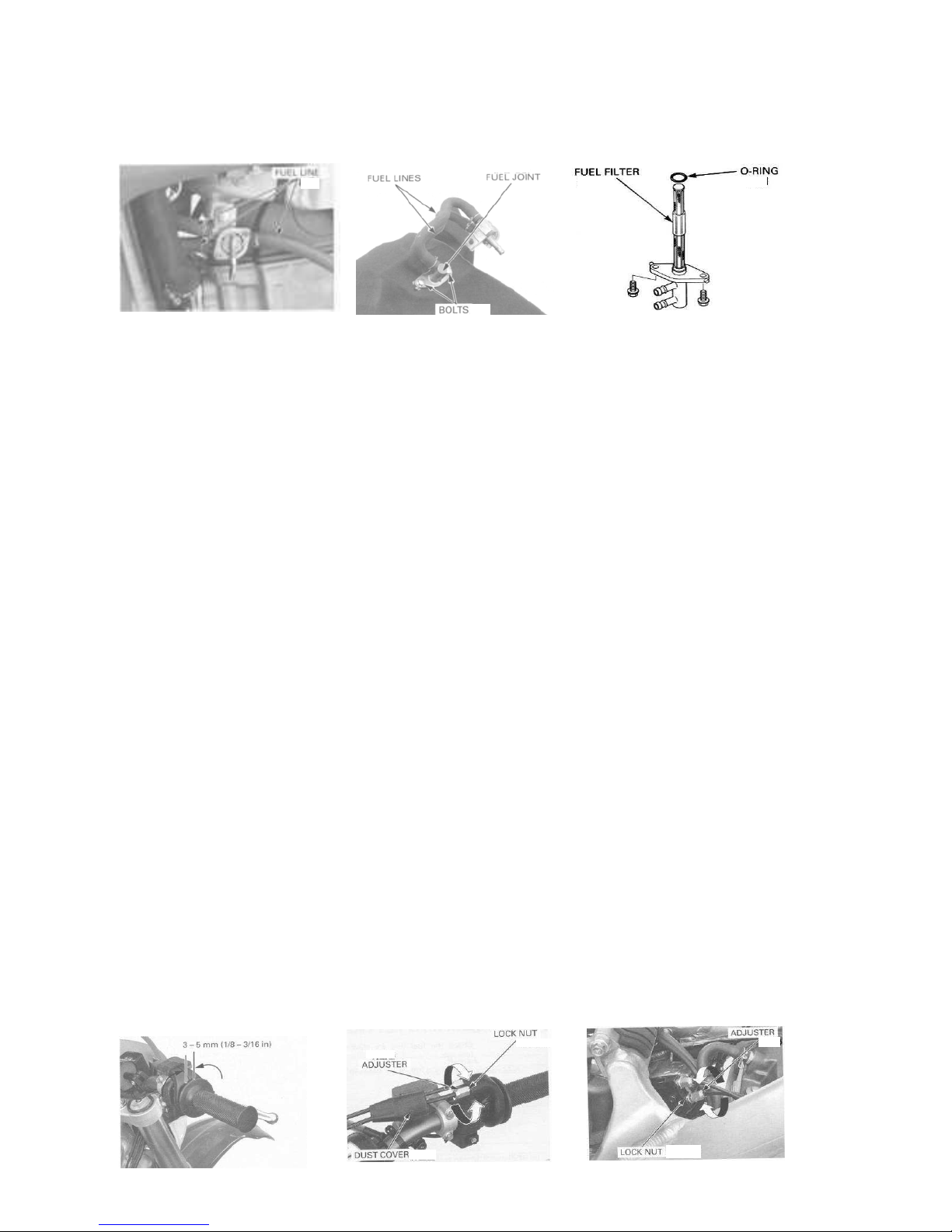
CARBURATION SYSTEM
Inspect the fuel line for damage or leak, if necessary replace fuel line.
FUEL FILTER
Remove
the
fuel tank. Drain the gasoline into a container and remove the fuel line, nuts and the clamps. Wash the fuel filter
and reinstall the O-ringand reinstall components onto the fuel tank.
Reinstall
the
fuel tank on the motorcycle. Make sure the tank does not leak.
THROTTLE
OPE
RATION
Check for smooth throttle grip at full
opening
and automatic full closing in all
steering
positions. Check the throttle cable and replace
them if they are
de t e r io ra t e d ,
kinked or damaged. Lubricate the throttle cable if
throttle
operation is not smooth.
Measure the free play at the throttle grip flange.
FREE PLAY
3
-5mm(1/
8-3/
16in)
Throttle grip free play can be adjusted at either end of the throttle cable.
Minor adjustments are made with the upper adjuster. Remove the dust cover from the adjuster. Adjust the free play by
Loosening
the lock nut and
turning
the adjuster.
Tighten the lock nut af ter
making
the
adjustment.
Reinstall the dust cover and recheck the throttle operation. Major
adjustments are made with the carburetor end of cable.
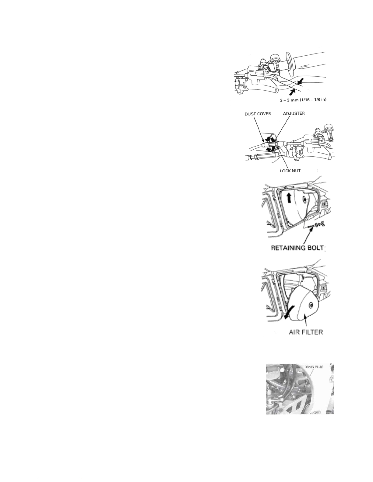
CHOKE LEVER
FREE PLAY:
2-3
mm(1/8
-3/1
6in)
Check for smooth choke lever operation and lubricate the cable if re-
quired.
Inspect the cable for cracks which could allow moisture to enter. Replace the
cable if necessary.
Measure the choke lever free play at the lever end. Choke lever free play can
be adjusted at the choke cable. Remove the dust cover from the adjuster.
Adjust the free play by
loosening
the lock nut and
turning
the adjuster.
Tighten the lock nut. Reinstall the dust cover. Recheck the free play at the lever.
AIR FILTER
Loosen the air cleaner
re t a in i n g
bolt. Remove the air filter. Remove
the
air
filter from the holder.
Thoroughly wash the air filter in clean non-flammable or high flash-point
cleaning
solvent. Then
wash the element again in a solution of hot water and
dishwashing
liquid soap. Clean the
inside of the air cleaner housing.
After cleaning, be sure there is no dirt or sand trapped between the inner and outer layer of the
cleaner. Wash again if necessary.
Allow the air cleaner to dry thoroughly.After drying, soak the air filter in clean Foam
Fi
l
ter
Oil or
an equivalent.
Apply air filter oil to the entire surface of the air filter and rub it with both hands to saturate the
element with oil.
Gently squeeze
out
excess oil. It is important not to over oil or under oil the element. Apply a
thin coat of grease or an equivalent to the sealing surface.
Assemble the air filter and the holder .Slip the air cleaner
retaining
bolt through the assembly.
Tighten the
retaining
bolt securely.
NOTICE
: If the air filter assembly is not installed correctly, dirt and dust may enter
the
engine
resulting
in wear of the piston ring and cylinder.
CRAN
KCA
SE BREATHER
Remove the breather hose drain plug, then drain any fluids or dirt from
the hose into a proper container. Reinstall the drain plug.

SPARK PLUG REMOVAL
Remove the fuel tank and disconnect the spark plug cap. Remove The
spark plug and inspect it for damage
Clean around the spark plug base with compressed air before removing
and be sure that no debris is allowed to enter the combustion chamber.
INSPECTION
Check the following and replace if necessary:
1) insulator for damage
2) electrodes for wear
3) burnt or discoloration
If the electrode is contaminated with accumulated debris or dirt replace
the spark plug.
(this motorcycle’s spark plug is equipped with an iridium center
electrode. Re- place the spark plug if the electrode is contaminated.)
Replace the plug if the center electrode is rounded as shown in the pic-
ture.
(Always use the specified spark plugs on this motorcycle)
RECOMMENDED SPARK PLUG (OR EQUIVALENT) Standard: DENSO:
IK24
Optional: DENSO: IK27
Check the gap between the center and side electrodes with a wire
Type feeler gauge
(To prevent damaging the iridium center electrode, use a wire type
Feeler gauge to check the spark plug gap. Do not adjust the spark Plug
gap if the gap is out of specification, replace with a new one.) Spark
plug gap: 0.4 mm
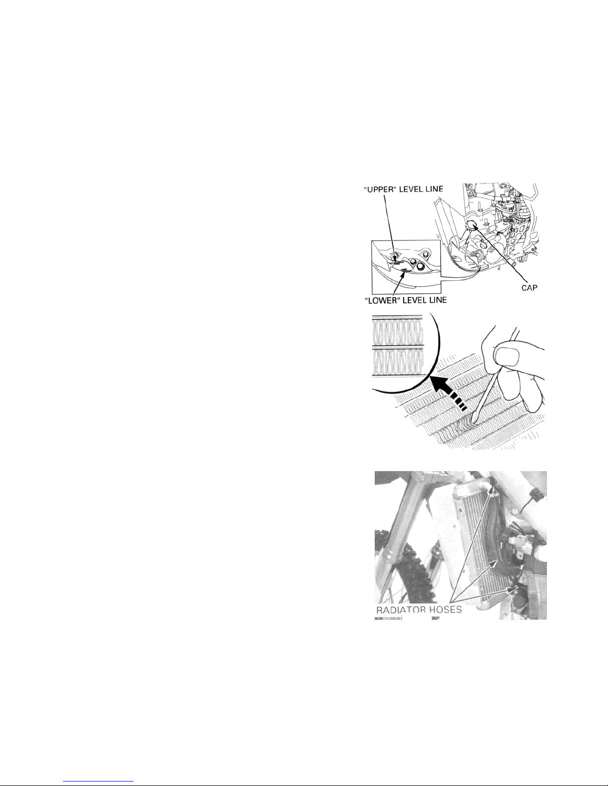
RADIATOR COOLANT
Inspect the level of the radiator coolant should be between “upper” and
“lower” when the motorcycle
running
under the normal
temperature. If need, put recommended coolant fluid in:
Remove the radiator cap. Put standard coolant concentration 1:1 to
the upper line and then reinstall the cap.
Recommended antifreeze
Professional coolant or an equivalent high quality ethylene glycol
antifreeze
containing
silicate free corrosion inhibitors.
COOLING SYSTEM
Remove the radiator grills. Check the radiator air passage for clogs
or damage.
Inspect the hoses for cracks and deteriorations.
Use low pressure water and a soft brush to wash off any dirt that may
be stuck in the radiator core.
Replace if
necessary.
Check the tightness of the hose clamps and
radiator
mounting
bolts.
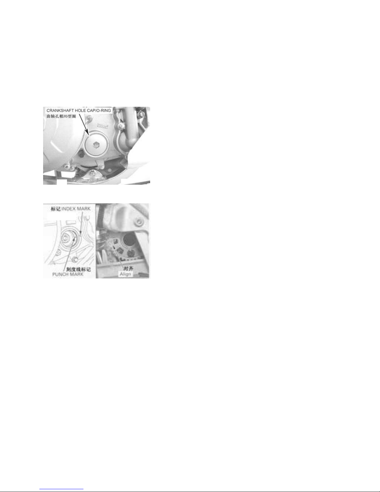
VALVE CLEANCE / DECOMPRESSOR SYSTEM
VALVE CLEARANCE INSPECTION
Inspect and adjust the valve clearance while the engine is cold
(below 35Ԩ/950 f)
Remove the cylinder head cover.
Remove the crankshaft hole cap and O-ring.
Turn the crankshaft clockwise to align the punch mark with the index
mark on the right crankcase cover. Make sure the piston is at TDC
(Top Dead Center) on the compression stroke.
Check that the index line on the cam sprocket aligns with the ”ᇞ”
mark on the cam holder.

INLET VALVE :
Insert the feeler gauge between the valve lifter and the cam lube. Check
the valve clearance for the intake valves using a feeler gauge.
Valve clearance IN: 0 .16+ 0.0 3mm
EXHAUST VALVE:
Insert the feeler gauge between the rocker arm and shim.
Check the valve clearance for the exhaust valves using a feeler gauge.
Valve clearance Ex: 0.28+0 .03mm
VALVE CLEARANCE ADJUSTMENT:
Remove the camshaft holder assembly
The shims my stick to the inside of the valve lifter. Do not allow the shims
to fall into the crankcase.
The shims can be easily removed with tweezers or a magnet.
Clean the valve shim contact area in the valve lifter with compressed air.
Measure the shim thickness and record it.
Table of contents
Other SSR Motorsports Motorcycle manuals

SSR Motorsports
SSR Motorsports SNAKE EYES XF250-GS User manual

SSR Motorsports
SSR Motorsports Lazer6 User manual

SSR Motorsports
SSR Motorsports SSR150 User manual

SSR Motorsports
SSR Motorsports Lazer5 User manual

SSR Motorsports
SSR Motorsports SR250S User manual

SSR Motorsports
SSR Motorsports SR300S User manual
Popular Motorcycle manuals by other brands

MV Agusta
MV Agusta Brutale 675 Workshop manual

APRILIA
APRILIA RSV MILLE - PART 1 1999 User manual content

Royal Enfield
Royal Enfield Himalayan 2018 owner's manual

MOTO GUZZI
MOTO GUZZI 2005 Griso 1100 Use and maintenance book

KTM
KTM 85 SX 19/16 owner's manual

Beta Motorcycles
Beta Motorcycles XTRAINER 250 2T EUROPA 2022 manual


