Störk-Tronic ST552G-XQ1TUR.109 User manual

Order number: 900350.053 V2.73 Page 1
© Störk-Tronic 2021 • www.stoerk-tronic.com • Subject to modifications.
ST552G-XQ1TUR.109
100...240V~
LN
B
RS485
ST-Bus
A
K1...K4: 8(1,5)A 250V~
K1 K2
F1
Pt100
12
1234
1234123
1
21
23
PWM
GND
PWM
Out
S1: PWM
Power
123
K3 K4
E1
1
21
21
2
43
E2
F1
TC
T
_
S2: 4...20mA
8(1,5)A
250V ~
K7
Deep-frying controller
Order number: 900350.053
As of: 02.11.2021 V2.73
The ST552G fryer controller consists of a mineral glass-based touch panel that can be easily integrated into existing or
newly constructed installations. The controller can be supplied with a voltage of 100...240V AC and has two displays, five
switching outputs and two digital switching inputs. A temperature sensor type Pt100 or a thermocouple can be connected.
Five LEDs each indicate the selected temperature setpoint and the selected time setpoint.
The controller is networked by means of an ST-Bus interface.
Sensor: Thermo couple, Pt100
Range: dependant on type of sensor
Front size: 154,8mm x 61,8mm
Installation size: 180 x 87mm
Tightness: Front IP65
Connectors: Screw terminal
Product description
Wiring diagram
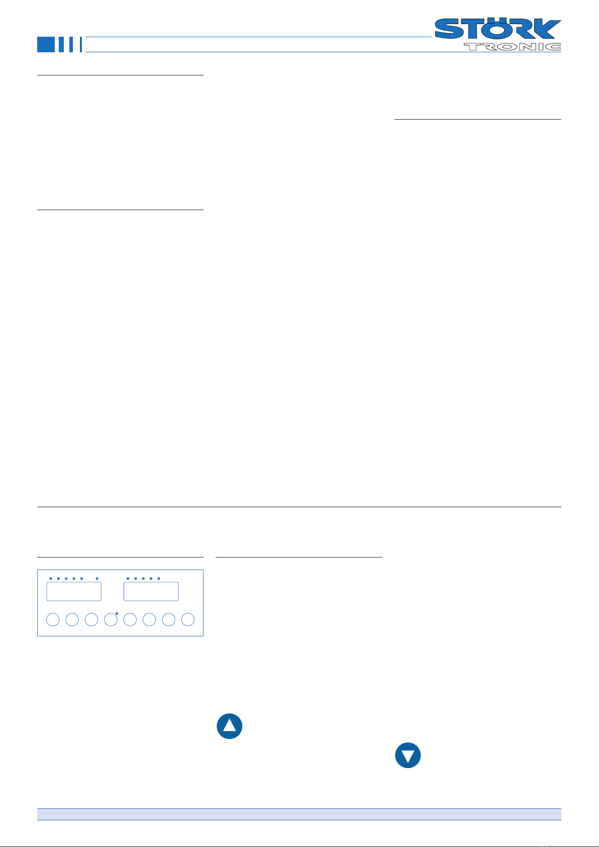
Design
The unit is designed as a complete installa-
tion unit and is intended for rear mounting.
The innovative capacitance keypad allows a
smooth glass front and makes the unit par-
ticularly suitable for applications with a high
degree of contamination. All inputs and out-
puts are connected at the rear. The unit fulfils
the function of a temperature controller with
timer functions and is designed for use with
deep-fat fryers.
Function
The front of the unit has a three- and
four-digit display, eight control buttons and
twelve LEDs. Five LEDs indicate the select-
ed temperature setpoint (“TEMPERATURE 1,
2, 3, 4, 5”), five LEDs indicate the selected
timer (“TIME 1, 2, 3, 4, 5”) and one LED indi-
cates the current status of the control output
(“HEAT”). The LED on the Melt/Turbo key
indicates the operating status selected there.
If it is on, gentle heating is in progress. The
reverse display direction can be set via pa-
rameter P17.
A temperature sensor type Pt100 or a ther-
mocouple type J is connected for recording
the actual control value. Two switching in-
puts allow the external start and stop of the
timer and the connection of an alarm contact
for over-temperature. In case of over-temper-
ature, the display shows “UEb” or “Hot”
flashing and the control is switched off. The
function of the switching inputs can be deac-
tivated via the parameterisation.
Four NO contacts and one changeover con-
tact are provided as output relays. The func-
tion “heating thermostat 1” or “heating PID”
can be selected for output K1 via the pa-
rameterisation; deactivation is also possible.
Output K2 has the basic function “cooling
thermostat 2” and can be used for an re-
lease function. Output K3 operates the bas-
ket lowering after timer start and output K4
the basket raising after timer stop, both of
which also apply when a timer is stopped in
between. Output K7 is assigned to the limit
value alarm.
The controller has the option of “gentle heat-
ing” in case the fryer fat is still solidified. This
slowed-down heating process (Melt func-
tion) is active after mains on and ends when
a limit value is reached that can be set below
the setpoint. If the fat has visibly melted, the
Melt/Turbo key can be used to switch to ac-
celerated heating even before the limit value
is reached. When cooling down, the turbo
characteristic is initially maintained; only be-
low 50 °C, the reloading of unmelted fat is
assumed and the controller automatically
switches back to gentle heating.
You can also enter a variable frying time.
Taking a parameterisable weighing factor
into account, the time of the started timer is
increased or reduced dynamically, depend-
ing on the control deviation.
A pair of limit values that can be set in the
parameterisation allows a temperature alarm
related to the actual control value, whereby
relative and absolute limit values can be
selected. In these alarm cases, the control
continues to run. An internal buzzer allows
an acknowledgeable warning signal.
Parameterisation
Parameterisation mode can be activated
by pressing the Temperature Up and Tem-
perature Down buttons simultaneously for
3 seconds. Parameter P1 appears in the
display. Use the Up and Down buttons to
scroll through the parameters. To access
higher parameters quickly, scroll backwards
using the Down button. Press the Melt-Tur-
bo button to activate the value of the current
parameter, the digit which can be changed
will be flashing. Use the temperature selec-
tion button to select other digits. Once, you
return to P1,... the changed value is saved.
Now, you can return to normal mode by
pressing Up+Down. After 60 seconds, the
controller returns to normal mode automat-
ically without saving any changes.
Displays
Display 1
T1 T2 T3 T4 T5 T6 T7 T8
Display 2
Display 1 (left): Temperature
LEDs 1...5 (left): Temperature selection
Display 2 (right): Timer
LEDs 1...5 (right): Timer selection
Top centre LED: Status heating output
Button LED: Gentle heating (Melt)
Function of the control buttons
General notes
With the present capacity keyboard, unde-
sired reactions of the controller are possible,
for technical reasons, when steam vapours
occur without the operator having pressed
a key. For these applications, a special de-
laying selection and setting mimic can be
selected (P47=1), in which an additional
key press is forced at the beginning of each
setting procedure. If this is not needed in
practice, it is possible to switch to the faster
selection and setting (P47=0, no delay).
Key 1: UP - Temperature
Use this button to increase a tem-
perature value activated via the
temperature selection. A delayed one-finger
setup is implemented. After tapping the but-
ton the display gets dark for a short period
(parameter P49) for unlocking. Once the
display comes back, the value is increased
without any further delay by tipping or keep-
ing the button pressed to increase the in-
crement and reach distant end values faster.
The maximal increment can be parameter-
ised.
For non-delayed key operation the timer side
has the same behaviour, if the actual value
is selected as the permanent display (P32
= 0). only the short darkening of the display
doesn’t take place.
Single-finger setup is implemented on the
parameter level, too. Here, the UP button is
used for switching to the following parameter
and for adjustment, after the value was acti-
vated with the Melt/Turbo button and the dig-
it to be adjusted was selected via the selec-
tion button. You can scroll through the digits.
Key 2: DOWN - Temperature
Use this button to reduce a temper-
ature value activated via the temper-
ature selection. The procedure corresponds
to increasing the value via the UP button.
The same applies to the parameter level.
Order number: 900350.053 V2.73 Page 2
© Störk-Tronic 2021 • www.stoerk-tronic.com • Subject to modifications.
General notes

The down button is also used for acknowl-
edgement of the buzzer. Since the timer re-
mains active when parameterisation mode is
activated, the buzzer can also be acknowl-
edged there.
Key 3: Temperature selection
Use this button to select the setpoint
to be used by the controller. Scroll
to select, each push of the button switches
the display further one step. The selected
temperature setpoint remains active even
after disconnection of mains supply. Special
presets are also possible.
In “delayed key operation” the selection
lamp goes off when initially pressed briefly,
then the button must be released and from
then on you can change instantaneously. In
non-delayed key operation the change takes
place immediately
.
Key 4: MELT/TURBO
Use this button to toggle between
gentle heating and fast heating
when the controller is switched on. This is
only possible below an adjustable threshold
below the limit value (P73). “MELT” mode is
always activated when the device is turned
on. A key delay can be set with parameter
P48.
The status LED is on during “gentle heat-
ing” mode (MELT function). It is possible to
select the reverse behaviour with parameter
P17, i.e. the LED is on during fast heating
(TURBO function).
With the “Superturbo” function, which can
be triggered with this key above the limit
value from P73, thermostatic control takes
place until a switch-off value (P15) set at
the setpoint is reached. In this zone, the key
toggles between thermostatic and PID char-
acteristics. The “Superturbo” option must be
enabled with P16. The status lamp always
indicates the active “Superturbo” by flash-
ing.
Key 5: UP - Timer
Use this button to increase a time
value activated via the time selec-
tion. One-finger setup is implemented. Keep
the button pressed, after a short unlocking
delay, the value is increased without delay.
Now, you can also release the button and
press it repeatedly briefly. In this case, the in-
crement increases so that you can set high-
er end values more quickly. Changing the
time is possible while the timer is running
down. The new value will be saved and used
immediately for the active timer operation.
The procedure in relation to the selected
key operation mode (parameter P47) corre-
sponds to the temperature side. In non-de-
layed key operation mode however, there is
no additional keypress on this side.
Key 6: DOWN - Timer
Use this button to decrease a time
value activated via the temperature
selection. The procedure corresponds to in-
creasing the value via the UP button.
Key 7: Timer selection
Use this button to select the time
to be used by the timer. Scroll to
select, each push of the button switches the
display further one step. The selected time
value remains active even after disconnec-
tion of mains supply.
Special presets are also possible.
The procedure in relation to the selected
key operation mode (parameter P47) corre-
sponds to the temperature side.
Key 8: START/STOP
As soon as this button is pressed
and released again, the selected
timer is started. The remaining time appears
in the display. The timer can be stopped at
any time. When the timer has elapsed, the
acoustic signal will be active for 3 seconds.
It can be acknowledged by pressing the
DOWN button. The timers have no influence
on the control operation. If you press the but-
ton for at least 2 seconds, the timer will be
stopped again.
In addition, you can turn the controller to
standby by pressing the button for at least
5 seconds. In the right display, OFF will
appear. Press the button again, to turn the
controller on again. Via the parameterisation,
you can also set up a button delay for the
restart (P43). In addition, you can change
the message displayed to OFF (parameter
P36). Via the parameterisation, you can also
deactivate the standby function completely
(parameter P41). In this case, the controller
will always be on after Mains ON
.
Key 4+8: Reset of fat
time registration
Pressing these buttons
simultaneously for at least 3 seconds will
reset the time registration. The warning mes-
sage OIL is withdrawn and, if necessary,
the control blocking is also cancelled. The
accumulated operating time is deleted. The
display briefly shows rES. Note that the re-
set is only possible if a warning status has
occurred or if blocking has occurred, and
also only below an adjustable temperature
limit. This is to prevent the user from continu-
ing to operate the fryer without changing the
fat. However, the reset can also be enabled
unconditionally.
Setpoint level
Para-
meter
Description of function Setting range Default
value
Temperature setpoints
S1 Temperature setpoint 1: P4 ... P5 110 °C
S2 Temperature setpoint 2: P4 ... P5 120 °C
S3 Temperature setpoint 3: P4 ... P5 130 °C
S4 Temperature setpoint 4: P4 ... P5 140 °C
S5 Temperature setpoint 5: P4 ... P5 150 °C
Timer setpoints
T1 Time 1: 0:00 ... 59:59 Min. 1:11 Min.
T2 Time 2: 0:00 ... 59:59 Min. 2:12 Min.
T3 Time 3: 0:00 ... 59:59 Min. 3:13 Min.
T4 Time 4: 0:00 ... 59:59 Min. 4:14 Min.
T5 Time 5: 0:00 ... 59:59 Min. 5:15 Min.
Order number: 900350.053 V2.73 Page 3
© Störk-Tronic 2021 • www.stoerk-tronic.com • Subject to modifications.
General notes
Para-
meter
Description of function Setting range Default
value
Cust.
value
General control parameters
P1 Delta W control circuit 2 -99...+99.0 K 10.0 K
P2 Hysteresis control circuit 1 0.1...99.0 K 1.0 K
P3 Hysteresis control circuit 2 0.1...99.0 K 1.0 K
P4 Bottom setpoint limitation 0...999 °C 0 °C
P5 Top setpoint limitation 0...999 °C 999 °C
P6 Correction actual value 1 -20.0...+20.0 K 0.0 K
P7 Display actual value 1 - -
P8 Initial temperature selection after Mains On 0: Selection as before
1...5: Selection of setpoint 1...5
0
P9 Initial time selection after Mains On 0: Selection as before
1...5: Selection of time value 1...5
0
PID parameter
P11 Control circuit 1: Proportional range in PID control 0.1…999 K 20.0 K
P12 Control circuit 1: Integral time in PID control (I portion) 0...999 sec.
(0 sec. = inactive)
500 sec.
P13 Circuit. 1: Derivative action time in PID control (D portion) 0...999 sec.
(0 sec. = inactive)
50 sec.
P14 Control circuit 1: Cycle time in PID control 2...100 sec. 10 sec.
P15 „Superturbo end“ around the setpoint -50...+50.0 K 15.0 K
P16 Switching mode of the Melt/Turbo key 0: Normal operation
1: Switch to „Superturbo“
1
P17 Behaviour of the MELT/TURBO LED 0: on during MELT
1: on during TURBO
0
Relay delay
P18 Switch-off delay for heating relay 0.0...99.0 sec. 0.0 sec.
Key lock
P19 Key lock (Setpoint adjustment disabled) 0: Not locked
1: Locked
0
Alarm parameters
P21 Lower alarm limit -99...999 °C/K -99 K
P22 Upper alarm limit -99...999 °C/K 200 K
P23 Hysteresis alarm, one side 0.1...99.9 K 1.0 K
P24 Alarm function 0: Alarm limit relative
1: Alarm limit absolute
1
P25 Special function in case of alarm 0: Not active
1: Display flashing, buzzer active
0
P26 Alarm suppression after Mains On 0...60 min. 0
P27 Buzzer duration when timer elapsed 0...60 sec.
(0 sec. = inactive)
5 sec.
P28 Buzzer type 0: continuous
1: pulsating
0
P29 Blinking after timer expiry 0...180 sec.
(0 sec. = inactive)
0 sec.
Display parameters
P31 Display mode basic level 0: Integral numbers
1: Resolution 0.5 K
2: Resolution 0.1 K
2
P32 Type of temperature display 0: Actual value display
1: Setpoint display
0
P33 Type of time display 0: Remaining time display
1: Operating time display
0
Order number: 900350.053 V2.73 Page 4
© Störk-Tronic 2021 • www.stoerk-tronic.com • Subject to modifications.
Parameter list

Para-
meter
Description of function Setting range Default
value
Cust.
value
P34 Temperature scale 0: Fahrenheit
1: Celsius
1
P35 Message in case of overtemperature 0: UEb
1: Hot
0
P36 Display in case of standby off 0: AUS
1: OFF
0
P37 Blinking mode during timer
(when the timer has elapsed, P29 is effective)
0: during buzzer
1: during buzzer and after timer has elapsed
2: different blinking intervals during/after the
timer and during activated buzzer
0
Key parameters
P41 Standby function 0: Not active
1: Standby with button click
2: Standby via ST-Bus
3: Standby with button and ST-Bus
1
P42 Internal buzzer mode 0 ... 15 (0 = buzzer inactive)
Bit mask (add values):
+1: Button klick
+2: Baking end
+4: Error, high temperature/sensor error
+8: Errors like an alarm relay
15
P43 Delay of Start/Stop key at Standby-On 0.1…5.0 sec. 1.0 sec.
P44 Delay before start of Turbo setup 0.0...2.0 sec. 0.5 sec.
P45 Maximum increment/decrement in turbo setup,
temperature setting
1...20 K 5 K
P46 Maximum increment/decrement in turbo setup,
time setting
1...20 sec. 5 sec.
P47 Key operating mode 0: standard mode (no delay)
1: delayed key operation
1
P48 Key delay for MELT/TURBO key 0.1 ... 5.0 sec. 0.5 sec.
P49 Key delay for setup (if P47=1) 0.5 ... 3.0 sec. 1.0 sec.
Input and output parameters
P51 Function of external input E1 0: No function
1: External start/stop
2: Access to parameter level
0
P52 Function of external input E2 0: No function
1: Message overtemperature
2: Feedback in case of "Gas" and "Gas+fan"
heating mode
0
P53 Switching mode input E2 0: Active when open
1: Active when closed
1
P54 Assignment output K1 0: Not active
1: Thermostat control circuit 1
(not with P56=2 and P56=3)
2: PID control circuit 1
2
P55 Assignment output K2 0: Not active
1: Thermostat 2
2: on together with controller on
1
P56 Type of heating 0: Gas heating with feedback
1: Electrical (or gas heating without feedback)
2: Gas+fan, gentle heating realised via fan
3: Gas+fan, gentle heating realised via burner
2
P57 Type of PWM / analogue signal (fan selection) 0: Active when high (230V~)
1: Active when low (24V=)
0
P58 Tolerance time for burner start and restart chance 1...20 sec. 10 sec.
P59 Min. on/off time during burner clocking 1.0...5.0 sec. 5.0 sec.
Order number: 900350.053 V2.73 Page 5
© Störk-Tronic 2021 • www.stoerk-tronic.com • Subject to modifications.
Parameter list

Para-
meter
Description of function Setting range Default
value
Cust.
value
Fan Parameters
P61 Minimum speed at fan 0...100 % (PWM/analogue signal) 30 %
P62 Maximum speed at fan 0...100 % (PWM/analogue signal) 100 %
P63 Maximum speed increase per 0.1 sec. 1...250 stages 4 stages
P64 Correcting variable in case of clocked operation 0...100 % (PWM / analogue signal) 50 %
P65 Lead/delay time of fan 1...60 sec. 5 sec.
P66 Time for start increase 1...60 sec. 5 sec.
P67 Starting boost (for P61/P62)0 ... 100% (PWM/analogue signal) 100%
Fryer parameters
P71 On time of heating clocking 1...255 sec. 60 sec.
P72 Off time of heating clocking 1...255 sec. 90 sec.
P73 Clock end below threshold -99...0,0 K -30 K
P74 Activation of burner clocking 0: Not active
1: Burner clocking below setpoint
1
P75 Duration of basket lowering at K3 at start of timer 0...30 sec. (0 sec. = inactive) 5 sec.
P76 Duration of basket raising at K4 at start of timer 0...30 sec. (0 sec. = inactive) 5 sec.
P77 Selection of post-frying time 0: Fixed time
1...20: Elastic time
0
P78 Activation of heating clocking 0: Not active, always turbo heating
1: Gentle heating
1
P79 Threshold for return to heating clocking mode 0.0...99.0 °C 50.0 °C
Operating time parameters
P81 Temperature limit for fat operating time elapsed 0.0...999 °C 999 °C
P82 Fat operating time until warning message 0...99 hrs. (0 hrs. = inactive) 0 hrs.
P83 Fat operating time until controller block 0...99 hrs. (0 hrs. = inactive) 0 hrs.
P84 Display of fat operating time ----- -----
P85 Temperature limit for reset of fat operating time
(only effective if P86 = 2)
-99...999 °C 100 °C
P86 Reset option of fat operating time 0: No restrictions
1: After warning message or blocking
2: After warning message or blocking plus
cool-down
2
Sensor and hardware parameters (if changed, Mains Off required)
P91 Selection of sensor type 0: Pt100 2-wire
1: Thermocouple type J (Fe-CuNi)
2: Thermocouple type K (NiCr-Ni)
0
P92 Display compensation ----- -----
P93 Software filter depth 1...64 8
P94 Mains frequency 0: 50 Hz
1: 60 Hz
0
P95 Type of analogue output 0: 0-10 V
1: 4-20 mA
1
LowFat and NoContact settings
H1 Temperature increase for test heating „LowFat“ 0.1…99.0 K 1.0 K
H2 Minimum duration for test heating „LowFat“ 0…240 sec.
(0 sec. = inactive)
0 sec.
H3 Maximum duration for test heating „NoContact“ 0…240 sec.
(0 sec. = inactive)
0 sec.
H4 Temperature increase for test heating „NoContact“ 0.1…99.0 K 1.0 K
H5 Max. temperature for LowFat- and NoContact settings 1…990 °C 60 °C
Order number: 900350.053 V2.73 Page 6
© Störk-Tronic 2021 • www.stoerk-tronic.com • Subject to modifications.
Parameter list

Order number: 900350.053 V2.73 Page 7
© Störk-Tronic 2021 • www.stoerk-tronic.com • Subject to modifications.
Function description
Para-
meter
Description of function Setting range Default
value
Cust.
value
Timer characteristics
tic Timer function 0: without multiple starts
1: with multiple timer starts
0
Address + version
L0 Controller address 1...255 5
Pro Program version -----
LowFat- and NoContact control
setting
General
Temperature monitoring a fryer can show
whether enough oil is available. The LowFat
and NoContact control settings provided by
the controller cary out this task. Low Fat and
No Contact operate independently, each
have their own parameters and can be de-
selected separately.
At the moment of turning on the burner the
control settings start running both at once
and a test heating starts.
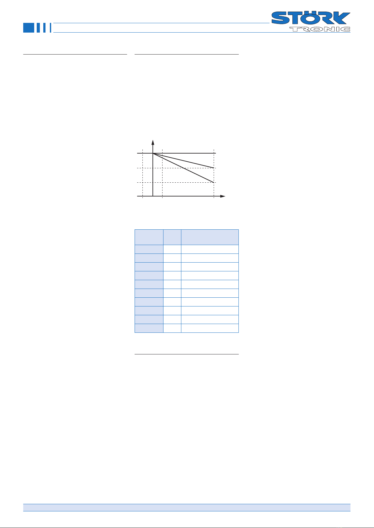
Heating dynamics at various amounts
of oil:
Rule of thumb: The more oil, the slower the
heating rate at a given heat output.
T
H1
H2 t
little oil
much oil
Start
The illustration shows the heating up with
small or large quantities in the deep fryer
tank
Fryer design features
The special features in the design of the
deep-fryer must be taken into account. The
temperature measurement value depends
on the thermal coupling of the sensor to the
oil or heating system. If the thermal coupling
disappears with little oil, then the tempera-
ture also increases slowly or not at all.
The illustrations show different constructions
and thermal coupling to the sensor.
Temperature behaviour of the different
designs
Example A:
If there is so little oil present that the sen-
sor is no longer immersed in oil, it measures
approximately the air temperature instead of
the oil temperature and hardly changes the
measured value during heating.
The lack of oil then becomes noticeable as
too little temperature rise.
Example B:
In design B, a mixing temperature can oc-
cur because the sensor has thermal contact
with the oil and the tank wall.
The temperature at the sensor rises when
the oil heats up, or when heat is transferred
to the sensor via the tank wall through heat
conduction.
Example C:
In design C, the sensor is always in thermal
contact with the medium.
In this case, the lower the amount of oil pres-
ent, the higher the temperature rise.
Example D:
Design D has the same characteristics as
design A.
Parameters involved
H1 Temperature rise for sample heat-
ing “LowFat”.
H2 Minimum duration for sample heat-
ing “LowFat”.
H3 Maximum duration for “NoContact”
test heating
H4 Temperature rise for “NoContact”
sample heating
H5 Maximum temperature for LowFat
and NoContact facial expressions
Order number: 900350.053 V2.73 Page 8
© Störk-Tronic 2021 • www.stoerk-tronic.com • Subject to modifications.
Function description
Test heating procedure and alarm
conditions
Once after start
After switching on the controller, it once exe-
cutes a test heating. This is to avoid that the
fryer is started, if there is no or insufficient
oil.
To fast temperature rise with little oil
Parameter H2 defines a minimum required
time for the temperature rise according to
parameters H1.
In case of a faster temperature rise the heat-
ing is switched off and an alarm with “lack of
oil” message is triggered.
To slow temperature rise without oil
Parameter H4 defines a minimum required
temperature rise for the duration according
to parameter H3.
A slower temperature rise may indicate that
no oil is present and the sensor is no longer
in the oil. The heating is switched off and an
alarm with “lack of oil” message is triggered.
Please note:
If a medium other than oil is used and the
heat output is changed, other parameter val-
ues will result.
In baking mode
In baking mode, i. e. above the temperature
of parameter H5, the process is no longer
reliable.
• Monitoring of the minimum tempera-
ture increase is not possible when cold
goods are thrown into the deep fryer.
• The monitoring of the maximum tem-
perature increase is not possible be-
cause this would require an unallowed
deviation from the setpoint.
Temperature range for LowFat- and No-
Contact settings
Parameter H5 sets a limit, up to which the
test heating is started after switching on the
controller.
Please note that the test heating is aborted if
this limit is exceeded.
Alarm and Reset
If the test heating causes an alarm, the
display flashes with “FAt” and the buzzer
sounds. The test heating is stopped and the
heater (i.e. burner and fan) is switched off.
The buzzer can be acknowledged immedi-
ately with the DOWN key. To reset the alarm
fill up oil and switch off and back on the con-
troller with the OFF key
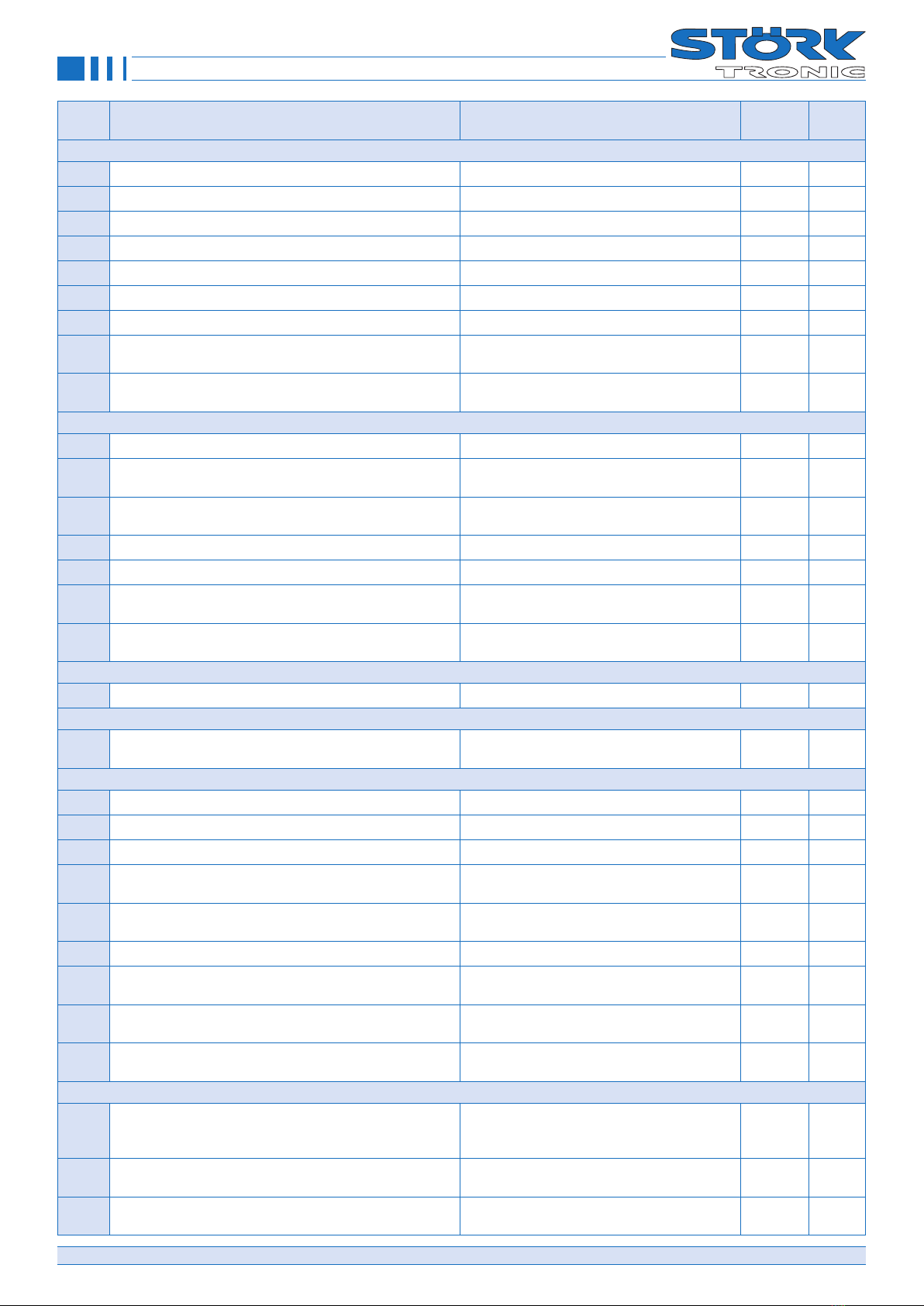
Selection parameter post-frying
time
With parameter P77, you can define if the
frying time is exactly the programmed time
or if the frying time is to be extended if the
fried material causes a temperature de-
crease.
Extension of the frying time, also referred to
as elastic time or post-frying time, depends
on the deviation from the setpoint. If the set-
point is exceeded, the time is reduced.
ΔT
P77=1
P77=10
P77=20
f(ΔT)
-10°C 10°C 100°C
Weighing factor in case
of variable frying time
Setpoint > actual value
tvar = tfix * f (ΔT, Tact)
1.0
1.5
1.5
Setpoint 180 °C, selected frying time 100 s
Act.
value
P77 Effective frying
time
180 °C 0 100 sec.
150 °C 0 100 sec.
180 °C 1 100 sec.
150 °C 1 120 sec.
180 °C 10 100 sec.
150 °C 10 135 sec.
180 °C 20 100 sec.
150 °C 20 150 sec.
125 °C 20 210 sec.
100 °C 20 300 sec.
Feedback in case of heating modes
“Gas” and “Gas+fan”
In the case of heating modes “Gas” and
“Gas + Fan”, a feedback signal detected via
switching input E2 can be used. The feed-
back confirms that the burner has started
properly. Otherwise, the control is stopped.
The feedback signal is considered in differ-
ent ways in the case of these heating modes.
Heating mode “Gas”
Control at the heating output is effected only
if the feedback is present on switching input
E2. Without the feedback, the heating relay
is not switched on. If the feedback is miss-
ing during the heating process, the relay is
switched off. In this heating mode, no error
message is triggered nor is it necessary to
acknowledge an error..
Heating mode “Gas+Fan”
Restart with controller switched off:
Control at the heating input will be activat-
ed upon request by the controller part. After
that, the system waits for receipt of the feed-
back (for the time set in parameter P58). If
the feedback is received at switching input
E2 of if it is already present at the time of the
request, the control operation is continued.
If not, the control operation is switched off.
The “HEAT” lamp flashes slowly signalling
the start error. To acknowledge and restart
the control operation, press the “OFF” but-
ton, i.e. switch to Standby Off and on again.
Burner failure with restart chance:
If the feedback fails during the control oper-
ation, the fan is switched back to minimum
speed according to parameter P61 imme-
diately. The system waits for the restart of
the burner and the return of the feedback
signal (for the time set in parameter P58).
The “HEAT” lamp flashes quickly signalling
the restart chance. If the feedback signal is
received again, the control operation is con-
tinued. If the feedback is not received within
this time, the control operation is switched
off. The “HEAT” lamp flashes slowly sig-
nalling the burner failure. To acknowledge
and restart the control operation, press the
“OFF” button, i.e. switch to Standby Off and
on again.
Deactivation of feedback
Via parameter P53, you can deactivate the
feedback function by reversing the switching
mode of switching input E2. In this case, the
controller will interpret the open switching
input, to which nothing may be connected,
as a feedback signal. Independent of this,
the feedback will also be deactivated if you
assign other functions to the switching input
via P52.
The control function of the deep fryer con-
troller is explained in the following and
will always be valid while the controller is
switched on.
Order number: 900350.053 V2.73 Page 9
© Störk-Tronic 2021 • www.stoerk-tronic.com • Subject to modifications.
Function description
Control function
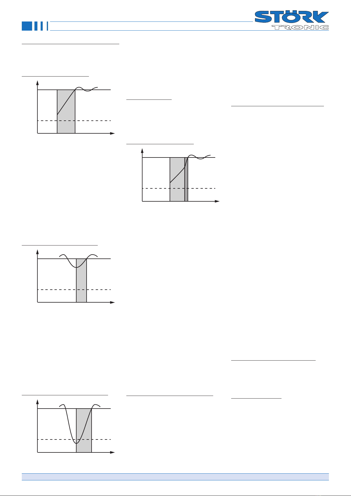
Heating phase without manual interven-
tion:
Heating phase after activation:
T
50°C
t
Setpoint
Heating phase
after activation
After activation and start of the controller, a
slow heating phase will always follow when
the fat is cold. This phase ends at latest
when the setpoint is reached. In this slow
heating phase, the heating relay clocks, i.e.
with the on time set in parameter P71 be-
ing followed by the off time set in parameter
P72. Slow heating is to ensure that con-
gealed fat is heated up gently at the start
of operation. Via parameter P73, you can
stop the slow heating phase before the set-
point is reached. If this is not desired, set
P73=0.0 K.
Heating phase after slight cooling:
T
50°C
t
Setpoint
Heating phase
after minor cooling
After a minor cooling down to temperatures
above 50 °C, e.g. by loading small amounts
of cold fat, the normal heating function of
the controller is maintained. The reheating
phase is therefore not slowed down; if the
thermostat function is set via the parameter-
isation, the heating relay does not cycle. If
the PID function is preset, the heating relay
only cycles within this range. The end of the
cycle set with P73 has no effect.
Heating phase after significant cooling:
T
50°C
t
Setpoint
Heating phase
after significant cooling
After significant cooling to temperatures be-
low 50 °C, e.g. loading of large quantities of
cold fat, the slow heating function is activat-
ed again. The heating relay cycles again like
in the initial heating phase, until the setpoint
or the cycle end below the setpoint defined
in parameter P73 is reached again. This is
to ensure gentle heating of the reloaded fat.
Control after heating
After the heating phase, the controller works
with the PID function based on parameter
group P11 to P14.
Heating phase with manual intervention:
Heating phase after activation.
T
50°C
t
Setpoint
Heating phase
with manual switchover
After activation and start, the slow heating
phase will start without manual intervention.
By pressing the quick heating button MELT/
TURBO, you can switch over to the normal
heating function. Now, the fat will be heated
more quickly. The heating relay will no longer
cycle based on the times set in parameters
P71 and P72 but based on the PID function
set via the PID parameters. The cycle end
defined via parameter P73 does not have
any influence after the manual intervention.
To undo the switch-over, press the MELT/
TURBO button again. Now, the heating relay
will cycle like before the manual change-over
again.
The manual change-over function can be
used for reducing the heating phase if the
fat has melted visibly and can be heated at
a higher rate without any damage. Manual
change-over between slow heating and tur-
bo heating is possible only if the controller
actually is in the heating phase, i.e. below
the threshold set via parameter P73. Above
this threshold, the turbo button has no func-
tion.
Heating phase after significant cooling
After significant cooling to temperatures be-
low 50 °C, e.g. loading of large quantities
of cold fat, a slow heating phase will start,
although the change-over to normal heating
mode is effected earlier; the heating relay
clocks like in the initial heating phase.
Thus, manual change-over to normal heat-
ing function is only effective for the current
heating phase and will become ineffective
as soon as the setpoint is reached, at the lat-
est. After that, as well as after mains failure
and restart, the controller is in normal oper-
ation mode with slow heating phase when
the controller is switched on and started or
restarted later or in the case of cool-down to
temperatures below 50 °C. The switch-back
threshold is can be set via parameter P79.
Clocking of automatic burner device in
the case of heating mode “Gas+Fan”:
Control to setpoint with “burner clocking”:
To obtain a better control to the setpoint
in the case of heating mode “Gas+Fan”,
clocking of the automatic burner device can
be activated. If the correcting variable per-
centage determined by the control part is
smaller than the lower speed limit of the fan
defined in parameter P61, the fan remains
at this minimum speed and the automatic
burner device is clocked until the setpoint
is reached.
In this case, the control part calculates the
on phases from 0...100 % based on the cor-
recting variable values, with a minimum on
time / minimum off time being enforced by
parameter P59. The feedback is handled
such that the time between the activation
of the heating output and the receipt of the
feedback signal is not considered as effec-
tive on time. Thus, the effective on time will
start only upon receipt of the feedback sig-
nal.
Below the burner clocking range, the auto-
matic burner device will always be on at first.
Above the burner clocking range, i.e. after
the setpoint was reached, the automatic
burner device and the fan are switched off
if the correcting variable becomes zero. For
the fan, lead and delay times as well as a
start-up boost are always effective.
If burner clocking is deactivated, the auto-
matic burner device will always be switched
on below the setpoint, and the control is af-
fected by defining the fan speed based on
the correcting variable, within the limits spec-
ified via parameters P61 and P62, across
the whole proportional range. Above the set-
point, the automatic burner device and the
fan will be switched off.
Gentle heating with “heating clocking”
Two operation modes are available for gen-
tle heating of cold fat, with the effective cor-
recting variable always being defined via the
ratio of the on and off times in P71 and P72.
Heat clocking with fan:
If P56=2 the so-called heating clocking is
affected only via the fan, the burner will be
on permanently. The speed value of the on
phase is defined by P64, in the of-period,
the minimum value defined by P61 is valid.
Note that the percentage value specified in
P64 is relative to the area of P61 ... P62.
Further the final value of the “on-period” is
not reached in case of very short turn-on
times in P71 because the fan speed in-
crease is reduced with parameter P63.

Order number: 900350.053 V2.73 Page 10
© Störk-Tronic 2021 • www.stoerk-tronic.com • Subject to modifications.
Function description
Heat clocking with burner:
If P56=3, the heating clocking is affected
by switching the automatic burner device on
and off at the time values defined in P71
and P72, with the fan always maintaining its
minimum speed according to P61. Param-
eter P64 has no function in this operation
mode.
Heating with “Superturbo”
To obtain always instant heat output in case
of need, you can change and activate the
switch option to “Superturbo” with P16. Now
the Melt/Turbo button activates the thermo-
static control, provided that the limit of P73
is exceeded. This mode is called “Supertur-
bo” and applies to all operating modes until
reaching the one time switch-off limit that
was established with P15. Thereafter, switch
again to “Superturbo”, if necessary. So you
can toggle with the button above the limit
from P73 between the PID control and the
thermostat behaviour, in which the hysteresis
of P2 is effective. If you switch within this
hysteresis to “Superturbo”, the heating is
switched on immediately and only from then
on, the hysteresis will be activated. Once
“Super Turbo” is active, there are no burner
cycles.
Above the cut-off line, which was established
with P15, the Melt/Turbo button is blocked
because an active “Superturbo” was already
deactivated and should remain also inactive.
You can only switch back to slower heating
(melt function) below the limit from P73.
Please note that the switch option to “Super-
turbo” remains in those named limits if the
controller was configured as a pure thermo-
stat with P54. In this case, the switch does
not create a change in the control behav-
iour, and it is recommended to disable the
“Superturbo” in P16. On the other hand,
you can activate “Superturbo” if you waive
in special cases the gentle heating phase
with P78.
The status of ”Superturbo” is always dis-
played with a flashing buttons light, it doesn’t
matter how P17 is configured
Switch-off delay for heating relay:
With parameter P18, you can define a
switch-off delay for the heating relay which is
effective in all operation modes. The param-
eter is provided for cases, where the ignition
of the gas heating is always delayed.
Caution: The setting P18 must be done tak-
ing utmost care, as it is active independent
of the control part. For this reason, short cy-
cle times might result in unintended perma-
nent heating.
Operation of the timer group
Version without multiple start (tic=0):
Single start:
After the start of a timer it is not possible to
select or start another timer. At the end of a
timer the buzzer sounds and the LED of the
concerning timer flashes while the buzzer is
on.
With parameter P28 the buzzer can be spec-
ified for continuous or pulsating operation.
Basket activity:
If the basket operation is activated (P75>0
and P76>0) the basket is lowered at start
of the timer and is raised at every stop of
the timer.
By keeping pressed the Stop key the timer is
cancelled and the basket is raised.
If the basket operation is deactivated (P75=0
and P76=0) the basket is not lowered or
raised. The timer works as above.
Please note that it is mandatory to always
adjust both parameters P75 and P76 either
to “0” or to a time value!
Version with multiple start (tic=1):
Multiple start:
After the start of a timer it is possible to se-
lect another time and start the timer. In the
display you always see the time of the se-
lected timer and the LED of this timer is on.
At the end of a timer the buzzer sounds
and the LED of the concerning timer flashes
while the buzzer is on.
The display shows the time of the selected
timer and the LED of this timer is on.
It is possible to start all 5 timers simultane-
ously, however a multiple start of a single
timer is not possible!
With parameter P28 the buzzer can be spec-
ified for continuous or pulsating operation.
Basket activity:
If the basket operation is activated (P75>0
and P76>0) the basket is lowered at every
start of a timer and is raised at every stop or
end of a timer.
If the basket is raised or the Start/Stop key is
pressed, the lapse of all timers is interrupted
and can be continued by restarting.
It is possible to finally stop all timers by
pressing the Start/Stop key for more than 4
seconds.
If the basket operation is deactivated (P75=0
and P76=0) every timer works independent-
ly and only the currently selected timer is
started, stopped or cancelled. By pressing
the Start/Stop key for more than 4 seconds
all timers are cancelled.
Please note that it is mandatory to always
adjust both parameters P75 and P76 either
to “0” or to a time value!
Longer blinking of the timer lamps:
It is possible to let the timer lights flash at
timer end for up to 3 minutes. This results in
a longer signalling of expired timers, if only
a short buzzer period. With parameter P29
the flashing duration is specified, at P29 = 0
is no further flashing.
The flashing can, like the buzzer, be ac-
knowledged with the down button. If a mul-
ti-start occurred, the flashing of all timers is
always acknowledged together.
Flashing during timer sequence, at buzz-
er sound and after a timer has expired:
If P37 = 2, flashing already takes place in a
fast flashing cycle during the timer sequence.
If an flashing time is set in P29, flashing now
takes place in a slow flashing cycle during
the buzzer time. After the buzzer is off, the
flashing continues for the specified time, still
in a slow flashing cycle. This flashing can
again be acknowledged with the down key
for all timers together.
Note once again that the flashing of the timer
lamps on expiry or after the end of the timer
can only apply to unselected timers if sever-
al timers are expiring or have expired.

Order number: 900350.053 V2.73 Page 11
© Störk-Tronic 2021 • www.stoerk-tronic.com • Subject to modifications.
Status messages
Display Cause Remedy
E1 Sensor error
(Heating relay and analogue output are switched off!)
Check sensor
Ptc Sensor error on compensation element for thermocouple
measurement (P91=1,2)
Repair of controller
UEb Overtemperature at E2 (P35=0, P52=1) -----
Hot Overtemperature at E2 (P35=1, P52=1) -----
FAt Alarm of the LowFat or NoContact control settings Check oil level and/or switch on/off by press-
ing OFF button
EP Error in parameter memory Repair of controller
OIL
Control active
Warning message, fat operating time is exceeded (see P82)Acknowledge with the temperature DOWN key
OIL
Control blocked
Control is blocked,, fat operating time is exceeded (see P82)Acknowledge with the MELT and START key
rES Reset of fat operating time (see P86)-----
Display flashing Threshold alarm (P25=1) -----
Timer lamp flashing Timer has elapsed (see P27 and P29)Acknowledge with the DOWN key
Lamp “HEAT”
flashing slowly
Burner fault (see P58)Switch on/off by pressing OFF button
Lamp “HEAT”
flashing quickly
Burner restart chance (see P58)Waiting for restart or burner malfunction
Lamp “MELT2”
flashing slowly
Thermostatic “Super Turbo” is active
---
flashing during setup
Button lock (P19=1) -----

Order number: 900350.053 V2.73 Page 12
© Störk-Tronic 2021 • www.stoerk-tronic.com • Subject to modifications.
Technical data
Analogue inputs F1: Temperature sensor Pt100 or thermocouple TC
Measuring range: Pt100 -80...+400 °C
TC -50...+400 °C
Measuring accuracy referred to controller at 25 C: +/-0.5 K and +/-0.5 % of measuring range
Digital inputs E1: External start-stop button
E2: Overtemperature signal contact from temperature limiter
Switching outputs K1: Relay, 8(1.5) A / 250 V~, normally-open contact (heating contact)
K2: Relay, 8(1.5) A / 250 V~, normally-open (control contact 2)
K3: Relay, 8(1.5) A / 250 V~, normally-open (raise basket)
K4: Relay, 8(1.5) A / 250 V~, normally-open (lower basket)
K7: Relay, 8(1.5) A / 250 V~, change-over contact (alarm contact)
S2: Linear analog output with 0 to 20 mA output range
PWM output S1: PWM output 3.6 KHz, output of PID correcting variable for control via a fan
Power supply 100 ... 240 V~ 50/60 Hz
Connectors Screw terminals, grid 5.00 mm, for cables up to 2.5 mm²
Ambient conditions Storage temperature -20...+70 °C
Operating temperature 0...55 °C
Relative humidity max. 75 % r.H., no condensation
Weight approx. 600 g
Enclosure type IP65 front, IP00 rear
Protection class Protection class II, rated voltage 250 V~
Interface Shielded 2-wire cable, twisted pair, maximum cable length 1000 m
Interface driver: RS485, galvanically not isolated.
The network must be designed in line topology with termination resistor of 120 Ohm on both sides.
Installation data The display unit is designed for installation in a switching panel (note dimensioned drawing).
Front size: 154.8mm x 61.8mm
Assembly size: 180 x 87mm
Assembly depth: approx. 25mm
25
1
7,3
154,8
180
61,8
62,1
155,2
172
79
This manual suits for next models
1
Table of contents
Other Störk-Tronic Controllers manuals


Popular Controllers manuals by other brands


Niles
Niles MVC100 installation guide

Morningstar
Morningstar SunSaver-10 Installation and operation manual

Hanna Instruments
Hanna Instruments HI 504 instruction manual

Omega Engineering
Omega Engineering HE-XE103 user guide

HomeyLux
HomeyLux 4406707 user manual

Mitsubishi Electric
Mitsubishi Electric MELSERVO MR-JET-G-N1 user manual


