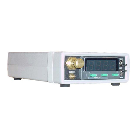
BioSpherix Proox 360 User manual

Proox Model 360
Manual
version 1.0 June 2005
This manual is intended to help our customers efficiently
setup and operate the equipment. We encourage not only all
installers, but also all users, to read this manual thoroughly.
Keep it handy and refer to it often. Save it for future
reference. If you have any problems or questions, please do
not hesitate to call. We are here to help.
Introduction
The Proox model 360 is a versatile and compact gas oxygen controller for people who
do oxygen sensitive work. Though designed to work with BioSpherix chambers the Proox
360 works in incubators, glove boxes, animal cages, refrigerators, plant growth chambers,
and many other semi-sealable chambers. Pratically any medium-large enclosure can be
fitted.
The unit works from
outside of the host cham-
ber by remotely sensing
and displacing air oxygen
inside the chamber with
another gas. Nitrogen or
an oxygen poor gas, is
used to lower the oxygen
level inside the host
chamber. Oxygen or an oxygen enriched gas is used to raise the oxygen level
within the host chamber.
Nominal range is 0.1-99.9% oxygen. Advanced
feedback algorithms handle practically any oxygen gas
dynamic. Infusion rates are adjustable up to 350
SCFH. Installation is easy. Operation is simple. The
unit moves easily from one host chamber to another.
Please read and follow the safety and operations
instructions on the following pages. Be careful. Oxy-
gen can be dangerous. Any pressurized gas can be
dangerous. Know what you are doing and do it safely.
1
Proox model 360
version 1.0
!!
Anyone who has not thoroughly read and under-
stood this manual, must never attempt to operate
the equipment.
6678 Route 17
Redfield, New York 13437
315-387-3414
FAX 315-387-3415
TOLL FREE US/CAN 800-441-3414
www.biospherix.com

Table of Contents
Safety Instructions........................................................................3
Components of the Proox 360......................................................4
User Supplied Parts.......................................................................5
Setup of Gas Supply......................................................................6
Proox 360 Front Panel Installation...............................................7
Proox 360 Back Panel Installation................................................8
Operation........................................................................................9
Program Functions Menu............................................................10
Configuration................................................................................11
Calibration...............................................................................12-14
Tuning......................................................................................15-18
Single Setpoint Control..........................................................19-20
Setting the Alarm Setpoint..........................................................21
Maintenance.................................................................................22
Warranty........................................................................................23
2
Proox model 360
version 1.0

SAFETY INSTRUCTIONS
ELECTRICAL POWER SOURCE unit should be connected to a power supply only of the
type described in the operating instructions or as marked on unit.
POWER CORD PROTECTION power supply cords should be routed so that they are not
likely to be walked on or pinched by items placed upon or against them.
ELECTRIC SHOCK do not remove cover of Proox 360 due to presence of uninsulated
"dangerous voltage" within product's enclosure.
ELECTRIC SHOCK unit should never be used where it can fall or be pushed into water.
ELECTRIC SHOCK if modifying host chamber, be careful not to drill or cut into electrical
wires hidden behind chamber wall. Never drill or cut blindly.
NONUSE PERIODS power cord of unit should be unplugged from electrical outlet when left
unused for long period of time.
FALLING OBJECTS AND LIQUID SPLASH care should be taken so that objects do not fall
on equipment and liquids do not spill, splash, or drip onto or into unit enclosure or
power cord.
PRESSURIZED GAS secure all connections with hose clamps. Never exceed pressure
limits. Bleed all lines before disconnecting. Wear safety glasses at all times.
LOW OXYGEN ATMOSPHERES never enter a chamber which has a low oxygen atmo-
sphere because of severe danger of suffocation. Host chamber should be in well venti-
lated room. Control gas (nitrogen or other low oxygen gas) continuously leaks out of
chamber and should never be allowed to build up in room outside of chamber.
HIGH OXYGEN ATMOSPHERES never enter a chamber which has a high oxygen atmo-
sphere due to danger of oxygen toxicity. Never smoke or allow any source of fire or
spark in or around a chamber with high oxygen atmosphere. Oxygen radically promotes
combustion and can be explosive. Host chamber should always be in well ventilated
room. Oxygen continuously leaks out of chamber and should never be allowed to build
up in room outside chamber.
VENTILATION unit should be situated so that its' location or position does not interfere
with proper ventilation. Neither Proox 360 nor host chamber should be in poorly venti-
lated areas.
HEAT unit should be situated away from heat sources such as radiators, heat registers,
stoves, or other appliances or processes that produce heat.
CLEANING do not immerse unit in water. Do not wipe unit with wet cloth or sponge or
paper. Clean only with a dry cloth.
3
Proox model 360
version 1.0

Components of the Proox 360
This section will familiarize you with the components that come with
the Proox 360.
4
Proox model 360
version 1.0
12VDC regulated power
supply
Gas fitting
Infusion tubing
Calibration chamber
with tubing
Oxygen gas sensor
Proox 360 unit
Short piece of 1/8 in. ID tubing
(may be a long piece, depend-
ing on chamber)
Oxygen Sensor Cable

User Supplied Parts
This section will describe any parts that you will need to provide, in or-
der to properly operate the equipment.
1. Qty. 1 regulator, per compressed gas source, either a one stage regulator or a two
staged regulator. Either way you will need two gauges on the regulator, one to monitor the
amount of gas in the tank and one to monitor the gas coming out of the tank. (2500 PSIG
input 0-60 PSIG output, recommended). PSIG stands for Pounds per Square Inch Gauge
as opposed to PSIA which stands for Pounds per Square Inch Absolute.
2. Qty. 1 compressed gas source (tank) of nitrogen. (If using for low oxygen levels).
3. Qty. 1 compressed gas source (tank) of oxygen. (If using for high oxygen levels).
5
Proox model 360
version 1.0

Control gas must be supplied through a 1/4 in. ID tube to the back panel of the Proox
360. The pressure must be regulated to 0-40 PSIG. PSIG stands for Pounds per Square
Inch Gauge as opposed to PSIA which stands for Pounds per Square Inch Absolute. For
best results use approximately 15-20 PSIG for control (refer to the “Tuning” section under
the “Power” heading for further information). Do not connect any tubing yet, wait until told
to do so in the “Calibration” section and “Single Setpoint Control” section.
The amount of gas used is determined by how the chamber is used, not the Proox
360. The Proox 360 uses the least amount of gas possible, which is only what the cham-
ber needs. The amount of gas used is dependent on: (1) The size and leakiness of the
chamber, (2) The amount of times and how long the chamber door(s) are opened, (3) The
oxygen level being controlled.
Use a one or a two stage, 2500 PSIG input, 0-60 PSIG output regulator at the source
of the compressed gas. It is best to have two gauges so that you can monitor the amount
of gas in the compressed source and also monitor the amount passing through the output.
Never allow the pressure coming out of the compressed source to exceed 40 PSIG or
damage will occur to the Proox 360. If the regulator is not near the Proox 360 then
there should be a shutoff valve upstream of the Proox 360 so as to have the ability to
control the gas flow. When taking off gas supply tube always make sure to shut off com-
pressed gas at the source first, then bleed the pressure out of the line and then take off the
tube from back of Proox 360.
Step-by-Step Procedure for Connecting Gas to Machine
1. Before connecting the regulator to the tank, close the regulator and make sure the tank
is also closed off.
2. Connect the regulator to the compressed gas source.
3. Connect the tubing from each compressed gas source to the Proox 360 when told to do
so in the “Calibration” procedures and the “Single Setpoint Control” procedures.
4. At this point you don’t have to open the regulator or turn on the gas. You will be turning
the gas on at the beginning of the “Calibration”/“Single Setpoint Control” sections, for now
just connect the regulator.
Setup of Gas Supply
This section will describe how to setup the gas supply, for information
on how to connect the gas supply to the machine, see the “Calibra-
tion” sections and the “Single Setpoint Control” section.
6
Proox model 360
version 1.0

Proox 360 Front Panel
Installation
The following steps will explain how to set up the front of the Proox
360 and prepare it for installation to a chamber.
1. Placing the Unit
Place the unit on a level secure surface
either on the chamber or within ten feet of
the chamber (length of sensor cable). Make
sure you can easily access the front panel.
2. Gas Connected Properly
Anytime a compressed gas supply is
connected you will need to make sure that it
is connected correctly. To make sure that
the gas is connected properly open the
bleed valve by turning the knob on the front
of the Proox 360 counterclockwise. If gas is
heard expelling out the “GAS BLEED” barb
on the front panel then the gas is connected
properly. Once you have confirmed the gas
is connected, close the bleed valve knob.
3. Connecting Calibration Cham-
ber
Attach the calibration chamber by
connecting the 1/8 in. ID tubing to the barb
labeled “GAS BLEED” on the front of the
Proox 360.
4. Infusion Rate Needle Valve
Gives you the ability to adjust the flow
rate. Adjust the needle valve labeled “INFU-
SION RATE” with flat head screwdriver turn
clockwise to decrease flow and turn counter-
clockwise to increase flow. Use this if you
change chamber size.You will need more
power for a bigger chamber and less power
for a smaller chamber.
5. Gas and Alarm Switches
Flip the “GAS” switch up to turn the
valve on and allow the gas to flow to the
chamber. Flip the “ALARM” switch down to
enable the alarm to sound.
7
Proox model 360
version 1.0
2
3
4
5

2
3
1
4
1. Power Supply
Plug the 12VDC regulated power sup-
ply into a wall outlet. Then plug the jack end
into the port labeled “12VDC” on back of the
Proox 360. The display on the front of the
Proox 360 should turn on.
2. Connecting Gas
Attach 1/4 in. ID tubing, coming from
the compressed gas source, to hose barb
labeled “GAS SUPPLY 40 P.S.I.G. MAX” on
the back of the Proox 360. Making sure that
the gas coming in never exceeds 40 PSIG
or damage will occur to the Proox 360.
3. Connecting Infusion Tube
Attach 1/4 in. infusion tube to “GAS
OUT TO CHAMBER” barb on back of the
Proox 360. Route the infusion tubing to the
chamber. If you need to reduce the size of
the tubing to 1/8 in. ID, use the provided gas
fitting. Attach the supplied gas fitting to the
infusion tube and attach the short piece of
1/8 in. ID tubing to the other end of the gas
fitting. This will attach to the chamber.
4. Connecting Sensor
Plug the jack end of the sensor cable
into the port labeled “SENSOR” on back of
the Proox 360. Plug the other end of the
sensor cable into the sensor itself by lining
up the key on the terminal with the key on
the connector of the sensor cable. Push in
and twist the ring on. The display on the
front of the Proox 360 should respond.
Proox 360 Back Panel Installation 8
Proox model 360
version 1.0
The following steps will explain how to set up the back of the Proox
360 and prepare it for installation to a chamber.

This section will give an overview of some of the different modes and
functions within the Proox 360.
RESET ALARM/ERROR
MESSAGES
When the alarm or
error condition has
been cleared,
momentarily press
both upkey and
downkey at the
same time.
CHANGESETPOINT
Press and hold star
key. Press up key to
increase setpoint.
Press downkey to
decrease setpoint. If
change requires
control output, SP1
indicator will flash.
VIEWSETPOINT In work mode,
press and hold
star key. Setpoint
is shown in
alternating display.
CHANGEOPTION
Index to required function. Press and
hold star key (current option
displayed). Press up and/or down keys
to display new setting.
Release star key.
IMPORTANT:Check
new selection
(alternating with
function) before
moving to another
function or exiting
program mode.
VIEWFUNCTION/OPTION
On release of up or
down key at
function, display
alternates with the
option selected.
ENTER/EXITPROGRAMMODE
Simultaneously hold both up and down
keys for 3 seconds. You enter
program mode from
normal operating
mode at the tune
function on level 1 in
the menu. You exit
program mode at
any point in the
menu, returning to normal operating
mode. With exit, any new instructions
get entered into memory.
ENTRY TO HIDDEN LEVEL 4
At "VEr" function on
level 3, press and hold
both upkey and
downkey
simultaneously for 10
seconds. To enter level
4
PROGRAM MODE
All configuration, calibration,
and tuning operations take place in
program mode. You access the
programmenu,navigatethroughit,
selectappropriateoptions,andexit
back to work mode.
Entry into menu is always at
same point, the "tunE"function on
level1.
During programming, control
withexistingsettingsismaintained.
Newsettingsarewrittentomemory
only upon exiting program mode.
Settingsareretainedinnon-volatile
memory for years even if unit is
unpowered.
Security locks can configure
certainoptionsunadjustable. How-
ever, all functions and locked op-
tions may be viewed even when
locked.
Exit program mode from any
place in menu. Exiting program
modereturnstoworkmodewithnew
settings.
WORK MODE
Workmodeisthenormalday-
to-day operating mode. Whether
controlling or not (parked), oxygen
concentration at the sensor is con-
tinuously displayed, unless pre-
emptedbyotheroperations.
Operations in work mode are
limited to: (1) view setpoint, (2)
change setpoint, (3) reset alarm/
error message, (4) enter program
mode.
CHANGE LEVELS
Multi-level menu of functions requires
navigating from level to level.
Index down key to
level function.
Release down key
to display current
level.
Press and hold star
key while using
down key or up key
to select new level.
Release star key to
display new level.
SINGLE LEVELNAVIGATION
Press up
or down
key once
to move to
the next
function.
Hold up or down keys to automatically
index through the functions. Always
index down to get to level function.
Operation 9
Prooxmodel360
version1.0

SelectAutotuneorPark
Proportional Band / Gain
or dead band width
Integraltime/Reset
(Automaticoffset)
Derivativetime/Rate
Derivativeapproach
control
Proportionalcycle-time
orON/OFF
Offset/Manualreset
LockmainsetpointSP1
AdjustalarmSP2
setpoint
Select SP2 Dead
Band Width or
Proportional band
SelectSP2ON/OFF
orCycle-time
ReadcontrolSP1
outputpower%
SP1manualpower
control%
SetSP1powerlimit%
SetSP2powerlimit%
SubsidiaryalarmSP2
mode:latch/sequence
MainalarmSP2
mode: strategy.
Selectdisplayresolution
(decimalpoint)
Setscalemaximum
Setscaleminimum
Selectsensorinput
ReadSP1control
outputdevice
ReadSP2alarm
outputdevice
Burn-outprotection
Selectoutputmodes:
Direct/Reverse
SelectSP1/SP2
L.E.D.modes
Sensorspanadjust
Sensorzeroadjust
Selectcontrol
accuracymonitor
Readmonitorresults
ReadAutotune
tuningdata
Functionsreset
Derivativesensitivity
Displaysensitivity
Disablealarm
annunciator
Disableprogram
auto-exit
Securitylock
Softwareversion
2
1
4
3
Ú
Ú
×
Ø
×
PROGRAMENTRYPOINT
Program Functions Menu
Selectunitsof
measurement
PROGRAM MODE FUNCTIONS MENU is arranged on 4 levels. Entry into menu is
bottom of level 1. Exit menu from any point. Level 4 is hidden for security;
there's one way in. Menu items are loosely grouped together according to
similar functions. Some functions are defaults
(hard or soft). Some are read only. Some are only
active depending on other function settings. Some
are used only in rare instances. Chances are
you'll have to become intimately familiar with only
a few of the important ones.
10
Prooxmodel360
version1.0

Configuration
Extensive configuration options in alarming, security, and display
functions all can be set later, if necessary. Only one main
configuration setting is required to start ... high or low oxygen.
SP1 control direct
SP2alarmreverse
SP1controlreverse
SP2alarmreverse
SP1 control direct
SP2alarmdirect
SP1controlreverse
SP2alarmdirect
HIGH/LOWOXYGEN
Enterprogrammode. Navigate
to"rEV.d"functiononlevel3.
Controloutputiseitherdirector
reverse. Direct means oxygen de-
creases as output decreases on ap-
proachtosetpoint. Reversemeans
oxygen increases as output de-
creases on approach to set point.
To control high oxygen levels,
set SP1 (setpoint 1) output
modetoreverse.To
control lowoxygen,
set SP1 output
mode to direct.
Mnemonic: "1r" or
"1d".
SECONDARY
CONFIGURATIONS
Alarmconfigurationoptions
include deviation, band, and
fullscale. Outputcanbereverseor
direct acting. Alarm intensity is
configurable by timed pulse pro-
portioning.
Security options against
people errors include set point
lock, set point range limits, and
limited menu access to prevent
unauthorized changes. Burnout
contingenciesandoutputoverload
limitsprotectagainstmachinemal-
functions.
Display resolution and sen-
sitivity,alarmannunciatorpriority,
and flashing indicator lights are
adjustabletoo.
All these settings are sec-
ondary to the main job of oxygen
control. Theyareexplainedelse-
where.
11
Proox model 360
version 1.0
Alarm SP2
outputalsosetsbut
isnotactiveuntilalarmisconfigured.
Set "2r" or "2d" later if necessary.

SENSORS
Thesensordrivesthecontroller.
Ifthesensorisnotcalibrated,itwon't
be accurate. If the sensor is not
accurate,controlwon't be either.
Everysensormustbecalibrated
both (1) initially when installed, new
orused,and(2)periodicallyoverthe
life of the sensor to compensate for
normaldrift.
Sensorsgenerateanelectrical
signal (output) which is linear and
directlyproportionalwithgasoxygen
concentration:
Troubleis,sensorsarenotiden-
tical. Although always linear and
directly proportional, raw output can
bequitedifferentforeachsensor:
Sensoroutputalsochangesover
time(drift),generallyinaslowdown-
warddirection. Sensorsremainlinear
butgraduallylosepower:
Calibration
Calibration is the key to control accuracy. Check calibration at least
once a week to have as much confidence as necessary in accuracy.
CALIBRATION
Calibrationelectronicallycor-
rectsforthedifferenceamongsen-
sors. Makesrawoutputlinesuper-
imposeoncalibrated line. Then all
sensorsreadaccurately:
Calibrationalsocompensates
for drift. Monitor drift with periodic
calibration checks. Recalibrate
whennecessary:
CALIBRATION
STANDARDS
Sensorsarecalibratedtostan-
dard gas mixtures with known oxy-
gen concentrations. Since sensor
output is linear, calibrating at two
knownpointsmakesallotherpoints
accurate as well.
Ambient air (21%) is always
one point. It's a handy standard.
Immerse sensor in air by simply
externalizingitfromchamber.
Control gas, either nitrogen
(0%)oroxygen(100%),istheother
point. Immerse sensor in control
gas by using calibration chamber
andbleedvalve.
Ofcourse,otherstandardscan
beusedaswell. Orcalibratetothird
party oxygen analyzers. Just be
confidentinyourstandard.
CALIBRATION MENU
FUNCTIONS
"SPAn"and"ZEro"functions,
onlevel3ofthemenu,calibratethe
sensor. Both adjust sensor output
line without disrupting linearity, but
eachworksdifferently.
The"ZEro"functionaffectsonly
the Y-intercept of the line, not the
slope. Itmovesthelineupanddown
withoutchangingtheslope. Always
dothe"ZEro"functionfirst:
Increasing makes the y-intercept more
positive (moves the line up) -
Decreasing makes the y-intercept
more negative (moves the line down)
The "SPAn" function adjusts
the slope of the line, but does not
affecttheY-intercept(setby"ZEro"
function). Always do "SPAn" after
"ZEro":
Raising increases slope:
Lowering decreases slope:
REMEMBER: never adjust
"ZEro" function without adjusting
"SPAn"functionafterwards. "ZEro"
affects"SPAn"setting,but"SPAn"
doesnotaffect"ZEro"setting.
12
Prooxmodel360
version1.0

HOW TO USE
CALIBRATION CHAMBER
The calibration chamber is a
toolforimmersingthesensorincali-
bration gases. It connects to the
bleedbarbonthefrontpanelvia1/8
in. ID tubing. It holds the tip of the
sensor in the gas stream.
First, connect the calibra-
tion chamber tubing to the "GAS
BLEED"hosebarbonfrontpanelof
the Proox 360.
Then insert the sensor tip into
thecalibrationchamber. Thesensor
holeissizedforasnugfitandallows
the sensor to be in the gas stream
withinthechamber:
Finally, with the calibration
chamber and the calibration tubing
connected,openthebleedvalveknob
on the front panel of the Proox 360
until you hear the gas expelling
slightlythroughthecalibrationcham-
ber:
CALIBRATION
PROCEDURE FOR LOW
OXYGEN CONTROL
(Nitrogencontrolgas)
1. Connect the 1/4 in. ID tub-
ing, coming from the compressed
nitrogen gas source, to the barb
labeled "GAS SUPPLY 40 PSIG
MAX"on the backoftheProox360.
Makesurethegasisregulatedto5-
40 PSIG. Never exceed 40 PSIG
or damage will occur to the unit.
For the best results use approxi-
mately15-20PSIG.
2.Makesuretheswitchonthe
front panel labeled "GAS" is in the
"OFF"position. Thiswillensurethat
no gas is being wasted while cali-
brating.
3.Checktomakesurethatthe
gas is connected properly by open-
ingthebleedvalveonthefrontpanel,
if gas is heard expelling from the
bleedbarbthenthegasisconnected
properly. Onceyouhaveconfirmed
that the gas is connected correctly,
closethebleedvalve.
4. Hook up the calibration
chambertothe"BLEED"hose barb
on the front panel of the Proox 360,
by using the 1/8 in. ID calibration
tubing. Slightlyopenthebleedvalve
knobonthefrontpaneluntilyoucan
hearthegasexpellingslightlythrough
the calibration chamber this will es-
tablisha 0%oxygenlevelwithinthe
calibrationchamber.
5. Insertthesensortipintothe
calibrationchamberandlet thesen-
sorstabilizein0%oxygen(minuteor
two). Watch the sensor's response
to immersion in nitrogen, in work
mode,totellwhenitstabilizes. Note
whetheroxygenreadingisaboveor
below"0.0"and byhowmuch.
6. Enter program mode by
holding down the "up" and "down"
buttonsforthreeseconds,navigate
to the "LEVL" function and while
holding down the " * " button, push
the "up" button until you reach "3".
Thennavigatetothe"ZEro"function
and raise the setting if reading was
low, or decrease the setting if read-
ingwashigh.Tochangethenumber
hold down the " * " button, push the
"up"or"down"buttonuntilyoureach
thedesirednumber. Thenumberin
the "ZEro" function stands for the
same amount in work mode. For
example:if you change the number
in"ZEro" function by ".2" the num-
berinworkmodewillchangeby".2",
but the number you see in the pro-
grammode isnotthesamenumber
you will see in work mode. Exit
programmodetoseethenewread-
13
Prooxmodel360
version1.0
ing by holding the "up" and "down"
buttons for three seconds. Repeat
these steps until reading is what it
shouldbe"0.0".
7. NowtosettheSPAN. Close
thebleedvalveknobthenremovethe
sensorfromthecalibrationchamber
andletitstabilizeinroomair. Watch
thesensor'sresponsetoimmersion
in 21% oxygen in work mode to tell
when it stabilizes. Note whether
oxygen reading is above or below
"21.0" andby how much.
8. Enter program mode,
changethe"LEVL"to"3",navigate
to "SPAn" function, and raise the
setting if reading in work mode was
low,ordecreasethesettingifreading
inworkmodewashigh. Exitprogram
mode to see new reading. Repeat
until reading is what it should be
"21.0". Thenumberin"SPAn"func-
tiondoesn'texactlycorrespondwith
the number in work mode, it is a
coarse adjustment, so use little ad-
justments until you reach "21.0".
Sensor is calibrated when it
reads 0% oxygen after stabilization
in nitrogen and 21% oxygen after
stabilization in room air. Once the
sensoriscalibrated,thenattachthe
sensorto the chamber.

CALIBRATION
PROCEDURE FOR HIGH
OXYGEN CONTROL
(Oxygencontrolgas)
1.Removesensorfrom cham-
ber and let it stabilize in room air
(minuteortwo). Inworkmode,watch
thesensorresponsetoimmersionin
21%oxygentotellwhenitstabilizes.
Notewhetheroxygenreadingisabove
or below "21.0" andby how much.
2.Enterprogrammodebyhold-
ing down the "up" and "down" but-
tons for three seconds,navigate
to"LEVL"functionandwhileholding
down the " * " button, push the "up"
button until you reach "3". Then
navigatetothe"ZEro"functionand
increase the setting if reading was
low,ordecreasethesettingifreading
was high. To change the number
hold down the " * " button and push
theupordownbuttonuntilyoureach
the desired number. Exit program
modetoseenewreadingbyholding
downthe"up"and"down"buttonsfor
threeseconds. Repeatuntilreading
is what it should be "21.0". The
numberinthe"ZEro"functionstands
for the same amount in work mode.
Forexample:ifyouchangethenum-
ber in "ZEro" function by ".2" the
numberinworkmodewillchangeby
".2",butthenumberinprogammode
is not the same number in work
mode.
3. NowtosettheSPAN. Con-
nectthe1/4in.IDtubingcomingfrom
thecompressedoxygengassource
to the barb labeled "GAS SUPPLY
40 PSIG MAX" on the back of the
Proox 360. Make sure the gas is
regulated to 0-40 PSIG. Never ex-
ceed 40 PSIG. For the best results
useapproximately15-20PSIG.
4.Makesuretheswitchonthe
front panel labeled "GAS" is in the
"OFF"position. Thiswillensurethat
nogasisbeingwastedwhilecalibrat-
ing. 5.Checktomakesurethatthe
gas is connected properly by open-
ingthebleedvalveonthefrontpanel,
if gas is heard expelling from the
bleedbarbthenthegasisconnected
properly. Onceyouhaveconfrimed
that the gas is connected correctly,
closethebleedvalve.
6.Hookupthecalibrationcham-
ber to the bleed barb on the front
panel of Proox 360. Slightly open
bleedvalveknobonfrontpaneluntil
youcanhearthegasexpellingslightly
fromthecalibrationchamberthiswill
establish an oxygen level of 100%
throughcalibrationchamber.
7. Insertsensortipintocalibra-
14
Prooxmodel360
version1.0
tionchamberandletsensorstabilize
in100% oxygen (minute or two). In
workmode,watchsensorresponse
to immersion in oxygen to tell when
it stabilizes. Note whether oxygen
readingisaboveorbelow"100.0"and
by how much.
8. Enter program mode,
change"LEVL"to"3"andnavigate
to "SPAn" function, and raise the
setting if reading was low, or de-
crease the setting if reading was
high. Exitprogrammodetoseenew
reading. Repeatuntilreadingiswhat
itshouldbe"100.0". Thenumberin
"SPAn" function isn't an exact
corresponsewiththenumberinwork
mode, it is a coarse adjustment. A
little adjustment goes a long way.
Sensor is calibrated when it
reads21%oxygenafterstabilization
in air and reads 100% oxygen after
stabilization in oxygen.
Oncethesensoris calibrated,
attach the sensor to the chamber.
TEMPERATURE
EFFECT
Temperature can affect cali-
bration. If sensor will be used in a
temperaturecontrolledchamber(eg.
refrigerator or incubator), always
bring sensor to operating tempera-
turefirst before calibrating. It takes
at least 15 minutes for sensor to
thoroughly equilibrate to tempera-
tureofsurroundings.
Temperature effect places a
timelimitoncalibrationprocedure. A
changeintemperaturewillnotaffect
the sensor reading for almost 5-6
minutes. It takes that long for tem-
peratureinsidethesensortochange.
Fortunatelysensorrespondstooxy-
gen much faster, within a minute or
two. Eliminatetemperatureinterfer-
encebypromptlycalibratingsensor
after externalization from chamber,
beforeithastimetochangetempera-
ture. Be ready. Have calibration
chamber in position. Calibration is
easilyaccomplishedbeforetempera-
ture starts to throw off sensor: 1-2
minutes to stabilize in low oxygen
standard gas followed by quick ad-
justmentof"ZEro"function,then1-2
minutes to stabilize in high oxygen
standard followed by quick adjust-
mentof"SPAn"setting,andit'sback
intothechamber.

Tuning
Tuning matches control parameters of Proox 360 to gas dynamics of
host chamber to achieve effective control.
TUNING
Differentoxygencontroljobsin
different chambers require specific
control parameters. Tuning means
settingthosecontrolparametersthat
result in acceptable control.
Which parameters to set, and
howtosetthem,dependsonthejob.
Is oscillation acceptable? If so how
much? Is overshoot permissable?
Undershoot? How much? For how
long? Is the load fixed or variable?
Doessetpointchange? Must recov-
ery be fast?
Capabilityexiststohandleprac-
tically any oxygen control job. How-
ever,themorecomplexanddemand-
ingthejob,themoreinvolvedtuning
becomes.
Tune only what's necessary to
accomplish the job. Any additional
control parameters probably won't
help,andmighthurt. Excessivetun-
ing can reduce control stability.
Most oxygen control jobs are
simple. Thus tuning is easy. Only a
few parameters need to be set. Ad-
vancedcontrolcapabilitiesareavail-
able,butusethemonlyifyouneedto.
Just watch the control process
andseehoweachcontrolparameter
affects it. This is the only definitive
way. Usually it's the easiest too.
Tuningtakestime. Ittakesgas.
It means sitting and watching the
controlprocess,sometimesoverand
over. Thereisnoshortcut. Trialand
erroristheonlywaytotellifatuneset
works. AlongwiththeProox360you
are provided with a "Control Param-
eters Chart", this chart has all the
pretuninginformationthatwas done
at the factory. Don't lose this chart,
but if you do then call the number at
the front of this manual to receive a
new copy.
Alwayschangeonlyonecontrol
parameter at a time. See how that
setting works first, before changing
another. Recordeachtuneset. When
satisfied with control, copy and set
asideforsafekeeping.
A tune doesn't have to be per-
fect to work. But don't stop short
either. Oncetuningisdoneanddone
right, it may never need further at-
tention.
POWER
First adjust power. Power is
theonlycontrolparameternotsetin
programmode. Oncepowerisset,
other control parameters may be
tuned.
Powerisafunctionofinfusion
rate. Themoregasinfusedperunit
time,thehigherthepower. Infusion
rate is adjustable up to 350 SCFH
(StandardCubicFeetanHour).
Infusion rate is a function of
gas supply delivery pressure. The
higher the pressure, the faster the
infusionrate. Adjusttheamountof
pressure to the approximate de-
siredinfusionrateandfinetunewith
theneedlevalveonthefrontpanel.
Gassupplydeliverypressureisset
at the pressure regulator on gas
source. Infusionrateisdependent
on the pressure of the gas coming
from the compressed gas source.
Never exceed 40 PSIG.
Proox360powermustroughly
match dynamic gas load of cham-
ber. Too little power and it takes
forevertoreachsetpoint. Toomuch
powerand control is unstable.
The bigger the chamber, the
more power (gas) it takes. For
example, a small baby incubator
might take 2-5 SCFH , but a tissue
culture incubator might take 10-30
SCFH.
The leakier the chamber, the
more power (gas) it takes. For
example, an incubator with a tight
seal might take 10 SCFH, but one
with a loose seal might take 20
SCFH.
There are methods to calcu-
latepower,butit'sfasterandeasier
toadjustpowerempirically. Watch
thecontrolprocessandadjustinfu-
sion rate so Proox 360 is able to
deliberatelypushoxygenfromam-
bienttopastsetpointundernormal
loadconditions.
Mostjobscanbetunedovera
relativelywide powerrange. Once
the other control parameters are
tuned, however, any change in the
power/loadbalancemayrequirere-
tuningthoseparameters.
STEPS:
1. Set gas supply delivery pressure.
Range 0-40 PSIG. For best
results use 15-20 PSIG.
2. Watch the number in work mode
approach the set point. If too fast
and unstable, turn the needle
valve counterclockwise to lower
the infusion rate. If too slow, turn
the needle valve clockwise to
increase the infusion rate. Never
exceed 40 PSIG.
ON/OFF CONTROL
Crude basic control. Suitable
whenprecise oxygen levels are not
necessary.
Infusion stops when oxygen
reaches setpoint and resumes only
whenoxygendriftsbackpastsetpoint.
Outputiseither100%or0%. Oscil-
lationsarenatural.
The only tune adjustment is
the dead band width. Dead band
width is distance between on-to-off
point and off-to-on point above and
below setpoint. Defines where no
switching occurs, but oscillation
does occur.
Thelargerthedeadbandwidth,
thelargertheoscillation,buttheless
switching on and off. Maximize the
dead band width to minimize wear
andtearonequipment. Setforlarg-
est acceptable oscillation.
The smaller the dead band
width, the less oscillation, but the
morewearandtear.
15
Prooxmodel360
version1.0

On/offtuninghasnoprovision
forfluctuatingloads. Blindlyresponds
only to on-to-off point and off-to-on
point. Change in load may change
oscillationamplitudeand/orperiod.
STEPS:
1. For on/off control, enter program
mode, navigate to "CYC.t"
function on level 1. Set "on.of".
Have to go down to "0" to get to
"on.oF"
2. Then set dead band width. Index
down to "bAnd" function and set
distance between on-to-off point
and off-to-on point.
PROPORTIONAL CON-
TROL
Proportionalcontroleliminates
oscillation. It controls steady-state
byweakeningpowerasoxygenlevel
approaches setpoint. When power
(gas infused per unit time) exactly
matches load (gas leaking out per
unit time), oxygen stabilizes.
UnlikeON/OFFcontrolwhere
poweriseither100%or0%,propor-
tionalcontrolcanadjustpowerany-
wherebetween100%and0%. Power
is adjusted by timing gas pulses.
"Proportional"meansgaspulsesget
proportionately smaller as the dis-
tance between oxygen level and
setpoint (SP1) gets smaller.
Pulses are timed by setting a
cycletimeandvariedbypercentage
of the cycle time. Maximum pulses
are 100% of cycle time. Minimum
pulsesare0%ofcycletime. Propor-
tionedpulsesarein between.
Timedpulseproportioningoc-
cursonlyoveranarrowbandofoxy-
genlevelscenteredaroundsetpoint.
Controlgasisinfusedfullblast(100%
output)withnotiminguntilitreaches
this band. Then it cycles. The
deeper it goes into the proportional
band, the shorter the pulses. Band
size determines how quick pulses
shortenandpowerthusweakens.
Somewhere between 100%
and 0% of the cycle time there's a
pulse time that holds steady state.
However,ifproportionalbandistoo
small, it may not be easy to find.
Smallchangesinoxygenwillcause
huge changes in output, similar to
ON/OFFcontrol. Oxygen will oscil-
lateandnever reach steady state.
On the other hand, if propor-
tionalbandistoowide,proportioning
inhibitsapproachtosetpoint. Power
starts decreasing way to soon.
Proportional band should be
bigenoughsothere'snogrossover-
shooteverytimeproportioningkicks
in, but not so big that there's need-
lesspulsinglongbeforeoxygengets
evencloseto setpoint.
Cycle time should be as long
as possible to minimize wear and
tear on equipment, but not so long
thatitbecomesunresponsive.
If no other control parameters
are set, proportional band centers
around setpoint SP1. All additional
parametersaccentuateproportional
control. Withoutproportionalcontrol
(prop.bandandcycletime),noother
parametersareactive. Someaffect
the position of the band, but not the
size. Some affect the size, but not
the position. None affect the cycle
time.
STEPS:
1. To tune proportional control, enter
program mode, navigate to
"CYC.t" function on level 1. Set
cycle time, anywhere from 0.1 -
81 seconds.
2. Then index down to "bAnd"
function and set proportional
band. Gas power is reduced, by
time proportioning action, across
this band centered around SP1.
3. Exit program mode to work mode
and watch control process. Note
whether process overshoots and
oscillates, or undershoots from
cycling long before reaching
setpoint.
4. Enter program mode, and
navigate to "bAnd" function
again. If process overshot and
oscillated, increase band size. If
process undershot and took long
to reach setpoint, decrease band
size.
5. Repeat steps 3-4 till steady state
is achieved, whether steady state
is at setpoint or not.
MANUAL OFFSET
Proportional band is basically
a "blind" control parameter. When
setalone,itpositionsitselfarbitrarilly,
centered around the setpoint.
Chancesaresteady-statewillnotbe
at setpoint.
If proportional control steady-
state is not at setpoint, the offset
mustbeeliminatedtomovesteady-
state to setpoint.
ManualOffset movespropor-
tional band by a fixed distance so
that steady-state is at setpoint. If
steady-stateis+0.3%oxygenabove
setpoint, then an offset of -0.3 will
move proportional band down so
pulse is perfectly proportioned to
match load at setpoint.
Manualoffsetworksgoodwhen
controllingagainstafixedload. Once
set, it makes proportional control
nearlyperfect. Noovershooteither.
STEPS:
1. Watch control process in work
mode till steady state is reached.
Note the variance from setpoint.
2. Enter program mode, navigate to
"oFSt" function on level 1, and
set number that offsets variance.
NOTE: "int.t" function on level 1
must be set to "oFF" to manually
adjust offset, otherwise "oFSt"
function is not active but read-
only.
INTEGRAL CONTROL
AUTOMATIC OFFSET
RESET
Proportional control jobs with
fluctuatingloads,requireautomatic
offset to keep steady state at
setpoint.
Integralcontrolparameterau-
tomatically and continuously moni-
tors divergences between setpoint
andsteadystate,andactstocorrect
offset by repositioning proportional
band.Changestheareabetweenset
pointlineandoxygenlevelline,and
shifts proportional band in proper
direction to minimize area. As load
changes, steady state follows
setpointifintegralistunedproperly.
Integralcontrolovershootson
initial start up and after significant
interruptions. Farawayfromsetpoint
it senses big offset, so it shoots
proportionalbandasfaraspossible
in corrective direction. Only after
passing setpoint does integral pick
up the need to bring proportional
band back to near setpoint.
Integral control parameter is
time. Resetsoffsetasfrequentlyas
you specify. If integral time is too
short,itrecalculatestoomanytimes
before oxygen moves much and
movesproportionalbandtoofartoo
fast. Result is oscillation. Eventu-
Oscillation
16
Prooxmodel360
version1.0

allyoscillationwilldampentosteady
state, if load hasn't changed yet.
If integral time is too long, it's
slow to respond. Steady state and
setpoint take a long time to merge.
STEPS:
1. Watch oxygen control process in
work mode under normal load
change. Note offset at one load.
While load changes, note time till
new offset stabilizes at steady
state. To change load open the
chamber door and ventilate.
2. Enter program mode, navigate to
"int.t" function on level 1, and
set integral time to 30-70% of
noted time. Range is 0.1 - 60
minutes.
3. Exit program mode to work mode.
Watch as normal load changes
occur, and note time till offsets
disappear.
4. Repeat steps 2 and 3 until control
is acceptable.
DERIVATIVE CONTROL
The most demanding control
jobistheonethathastobefastand
tight under fluctuating loads. With
power and proportional band tuned
aggressively (high power, narrow
band), conditions are ripe for over-
shoot. Addintegralactionandover-
shoot is virtually guaranteed, at
startupandafterlargedisturbances.
Derivativecontrolsuppresses
overshoot. Italsospeedsresponse
to disturbances, large or small.
Derivativealgorithmsmeasure
rateand direction of change of oxy-
gen in relation to setpoint. Then
temporarily, but quickly shifts pro-
portionalbandinoppositedirection,
byadistanceproportionaltotherate
of change. The faster the change,
thefurther it shifts. Shift isjust long
enoughto"extract"anoutputdeter-
mination.
Theeffectistoquicklyweaken
poweron approach tosetpoint,and
quickly boost power if oxygen sud-
denlypullsawayfromsetpoint. Prop-
erlytuned,derivativeshouldnotdis-
turbproportionalorintegralactionat
steady state.
On fast approach to setpoint
withoutderivative,whenoxygenfirst
hitsproportionalbandtheinitialpulse
might be 97% of cycle time. That's
notveryweak. Thenextpulsemight
besignificantlyless,butbythattime
it's too late. Oxygen changed too
fast. Overshoot already occurred.
Whenintegralactionfinallykicksin,
it's way too late.
With derivative, fast oxygen
changeimmediatelypullsuppropor-
tionalband. Thenfirstpulsemightbe
1%ofcycletime. Thisquicklyslows
approachtosetpoint. Slowerrateof
change calculation might only "ex-
tract" a pulse of 12% of cycle time.
Slower still, maybe 19%.
As rate of change of oxygen
decreases, derivative action de-
creases. At steady state there's no
derivativeaction. Ideallyatthatpoint
oxygenisnearsetpointandintegral
actiontakesover.
Derivative also speeds re-
sponse to disturbances. Without it,
as oxygen quickly diverges away
from setpoint, the first pulse from
proportional control band might be
only 22% of cycle time, the second
pulse53%,thethird87%,andbythe
timeoutputgoesto100%,oxygenis
faraway.
Withderivative,thefastchange
inoxygenawayfromsetpointwould
immediately pull proportional band
back toward setpoint and result in
100%outputbeforeoxygengetstoo
far. Derivativecontrolishardestto
tune. Propersettingisverysensitive
to gas dynamics and other control
parameters. Ifitisnotrequired,keep
it off as it will tend to reduce control
stability.
Derivative parameter is time.
Setsrateofcorrectiveaction. Rule-
of-thumb: set 3-8 times faster than
integral. Iftooshortitinhibitsreach-
ing setpoint and slows response to
upsets. If too long, it oscillates and
overcorrects. Is only active in pro-
portionalband.
STEPS:
1. With power, proportional, and
integral parameters set, watch
control process in work mode.
Note overshoot. Next open
chamber briefly to induce large
upset in control. Note speed of
response.
2. Enter program mode, navigate to
"dEr.t" function on level 1,and
set derivative time. Range 0.1 -
0.4 of integral time.
3. Exit program mode, air out
chamber, watch control process
and note overshoot on approach
and response to disturbance.
4. Re-enter program mode, and
navigate to "dEr.t" function
again. If too much overshoot on
approach and too slow response
to upset, decrease derivative
time. If approach to setpoint is
inhibited and response under
corrects, increase derivative
time.
5. Repeat steps 3-4 until overshoot
on approach and response to
upset is acceptable.
17
Prooxmodel360
version1.0

DERIVATIVE APPROACH
CONTROL
Derivative action (1) sup-
presses overshoot and (2) speeds
responsetoupsets. However,itmay
not always be possible to do both
withone setting. Depending onthe
power/loadbalance,sometimesde-
rivativetunedforquickresponsewill
notsuppressovershootenough.
Derivative approach control
parameter "dAC" solves this prob-
lem. Ittunesovershootindependent
of normal operating parameters by
controlling when derivative action
startsonapproachtosetpoint. Nor-
mallyderivativeactionisonlyinpro-
portionalband. "dAC"isamultiplier
ofproportionalband.
Thesmallerthe"dAC"setting,
the closer to setpoint derivative ac-
tion begins. Too small and oxygen
overshoots. Toolargeandapproach
isslowed and stepped.
STEPS:
1. With power, proportional, and
integral parameters tuned, and
derivative time tuned for fast
response to upsets, watch
control process in work mode.
Note approach to setpoint.
3. Repeat steps 1-2 until control is
acceptable.
2. Enter program mode and navi-
gate to "dAC" function on level 1.
If overshoot suppression is
needed, increase multiple of
proportional band. Range is
0.5 - 5.0. If approach is stepped
and slow, decrease multiple.
DERIVATIVE SENSITIVITY
This parameter compensates
when power/load balance is such
thatderivativesuppressesovershoot
but does not sufficiently speed up
response to upsets.
Derivative sensitivity is frac-
tion multiplier of derivative time.
Range is 0.1 - 1.0. By fractioning
derivativetimeitspeedsactionupto
10 times faster.
STEPS:
1. With power, proportional, and
integral parameters tuned, and
derivative time tuned for over-
shoot suppression, watch
control process in work mode,
introduce upset by opening
chamber door(s), and note
speed of response to upset.
18
Prooxmodel360
version1.0
2. Enter program mode and navigate
to "dEr.S" function on level 4. To
get to level 4 go to "VEr" on level
3 and press both up and down
buttons and hold for 10 sec-
onds. If response to upset is too
slow, decrease setting (limit is
0.1). If response is too fast
resulting in overcompensation,
increase setting (limit is 1.0).
3. Repeat steps 1-2 until control is
acceptable.
AUTOMATIC TUNING
Ifoxygensetpointissufficiently
far away from outside air (20.8),
Proox 360 can calculate it's own
control parameters. It runs a few
testsonhostchamber. Takesafew
measurements. Calculatesoptimum
control parameters, and sets itself.
Ifsetpointisnotfarfromambi-
ent, autotuning will not work.
Autotuningsetsallcontrolpa-
rameters. It can't distinguish when
some are not needed. Thus some
jobsautotunedareovertuned.
Evenjobsthatareautotunable,
usuallyrequiresomemanualtuning
afterwardstofinetune.
Autotuning is most useful in
toughjobsthatrequirecomplextun-
ing. Gets you close fast (some-
times very close). Thus saves on
time and gas.
Autotuninginstructionswillbe
in the next version of this manual.

Single Setpoint Control 19
Prooxmodel360
version1.0
This section will describe how to use single setpoint control with the
Proox 360. Single setpoint control is a way to control the level of gas in
the chamber. Depending on if you want to operate at a low level of oxy-
gen (below 21.0%) or a high level of oxygen (above 21.0%) will determine
what gas you use. For more information, see the “Operation” section of
this manual. To set a setpoint on the controller, follow these steps:
Single setpoint control using a low level of oxygen:
1. Make sure the compressed nitrogen gas supply is connected to the back panel of the
Proox 360 at the “GAS SUPPLY 40 PSIG MAX” barb. Make sure that the infusion tube is
connected to the Proox 360 and the other end is connected to the chamber.
2. Open the regulator on the compressed nitrogen source to 0-40 PSIG, Never exceed 40
PSIG or damage will occur to the unit. For the best results use approximately 15-20
PSIG (refer to the “Tuning” section under the “Power” heading for further information).
3. Check to make sure that the gas is connected properly by opening the bleed valve on
the front panel. If gas is heard expelling from the bleed barb then it is connected correctly.
Once you have confirmed that the gas is connected properly, close the bleed valve.
4. To set a setpoint, push and hold the “*” button. While holding the “*” button use the “up”
and “down” buttons to adjust the “set” to read what you want the setpoint to be. Once you
have adjusted the number to the desired reading, release the “*” button.
5. Flip the switch on the front panel labeled “GAS” upward. This will allow the gas to enter
the chamber. The controller will begin to go towards the new setpoint.
Single setpoint control using a high level of oxygen:
1. Make sure the compressed oxygen gas supply is connected to the back panel of the
Proox 360 at the “GAS SUPPLY 40 PSIG MAX” barb.
2. Open the regulator on the compressed oxygen source to 0-40 PSIG, Never exceed 40
PSIG or damage will occur to the unit. For the best results use approximately 15-20
PSIG (refer to the “Tuning” section under the “Power” heading for further information).
3. Check to make sure that the gas is connected properly by opening the bleed valve on
the front panel. If gas is heard expelling from the bleed barb then it is connected correctly.
Once you have confirmed that the gas is connected properly, close the bleed valve.

Single Setpoint Control cont.
4. To set a setpoint, push and hold the “*” button. While holding the “*” button use the “up”
and “down” buttons to adjust the “set” to read what you want the setpoint to be. Once you
have adjusted the number to the desired reading, release the “*” button and the controller
will begin to go towards the new setpoint.
5. Flip the switch on the front panel labeled “GAS” upward. This will allow the gas to enter
the chamber.
20
Proox model 360
version 1.0
Table of contents
Other BioSpherix Controllers manuals
