Stac Zero Powermeter Quick start guide

1
Rev 3.0
Powermeter
Upgrade Manual

1
Welcome to the world of power training!
Congratulations on purchasing your STAC Zero Powermeter upgrade!
You will now be able to track your progress with real numbers, and
make use of online training apps. In our experience, training with the
Powermeter has led to substantial improvements in performance.
Follow the steps outlined in this manual and the upgrade process should
about 10 minutes.
Happy riding,
-The STAC Performance team
Table of Contents
UPGRADE AND TRAINER COMPONENTS..........................................................2
UPGRADE STEPS ..............................................................................................3
WHEEL MAGNET ALIGNMENT..........................................................................6
HEIGHT........................................................................................................6
CONCENTRICITY...........................................................................................7
PARALLELISM...............................................................................................8
POWERMETER SETUP AND CONFIGURATION................................................11
______________________________________________________
REQUIRED TOOLS
4mm Allen key
(Included with your original STAC Zero purchase)
5/32” Torx screwdriver.
3mm Allen key

2
UPGRADE AND TRAINER COMPONENTS
UPGRADE KIT
1. POWERMETER
2. STRAIN GAUGE
3. SET SCREW
4. WIRE
5. MAGNET SENSOR
6. 2 SCREWS
TRAINER COMPONENTS
RESISTANCE UNIT:
1. MOUNTING BOLTS
2. QUICK RELEASE
3. CALIPER
4. MAGNET ARRAY
5. MAGNETS
6. ALUMINUM BEAM
1
6
2
5
4
3
3
4
3
UPGRADE STEPS
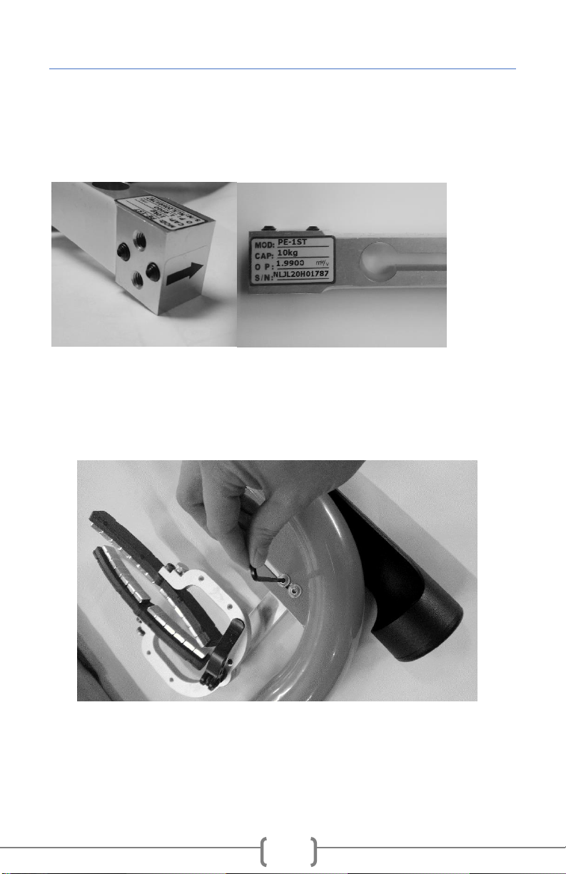
1) Confirm that the 2 Set Screws protrude slightly from the Strain
Gauge, as shown (Figure 1). If they do not, turn the Screws to the
right using the 3mm Allen Key until they extend past the Strain
Gauge by at least 2 threads.
Figure 1
2) Undo the two Mounting Bolts using a 4mm Allen key (included with
your original STAC Zero purchase) and remove the Resistance Unit
from the Frame (Figure 2).
Figure 2

4
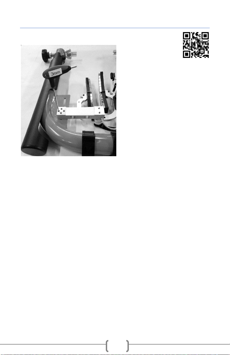
3) Set up: a. Rotate the Magnet Array to the
open position.
b. Loosen the Quick Release
slightly so the Calipers can be
moved by hand
c. Open the Calipers and place the
Resistance Unit face down on a
flat, non-magnetic surface
(Figure 3).
Note: This allows you to remove
the Beam from the Quick Release
without the Magnets snapping
together.
4) Unscrew the Quick Release until you can remove the Aluminum
Beam (Figure 3).
Note: Make sure not to remove the thread of the Quick Release from
between the Calipers, as this will cause a spacing washer to slip out.
5) Thread the Quick Release into
the threaded hole on the Strain
Gauge nearest to the Wire, with the
Wire facing away from the
Magnets. Tighten the Quick Release
(Figure 4).
Figure 3
Figure 4

5
6) Snap the plastic casing of the
Powermeter onto the Caliper
that is directly touching the
Strain Gauge. Align the screw
holes and tighten the screws
using a 5/32” Torx screwdriver
(Figure 5).
7) Remount the Resistance Unit
on the Frame with the Mounting
Bolts (Figure 6).
8) Mount your bike on the
trainer. Loosen the Mounting
Bolts slightly, and adjust the
Resistance Unit vertically so the
Magnet Holders line up with your
brake track. Tighten the Bolts.
Figure 5
Figure 6
6
WHEEL MAGNET ALIGNMENT
Support Video:
“Wheel Magnet
Alignment”
Due to some slight variation, the
Magnets may not be parallel to
your wheel after the upgrade is
executed, however this is easily
adjusted. Perform this step with
the bike mounted on the trainer
so you can see the results of the
adjustment.
Pictured (Figure 7): Location of
Set Screws.
Adjust the Set Screws using a 3mm Allen Key.
Adjust the Mounting Bolts using a 4mm Allen Key.
HEIGHT
Your Magnet Array should be level with your bike’s brake track. If the
Magnet Arrays are the correct height, proceed to the next section. If the
Magnet Array is sitting too low (touching the tire) or too high (not
contacting brake track):
1. Loosen the 2 Mounting Bolts and move the Resistance Unit
lower or higher as needed. Re-tighten the Mounting Bolts.
2. Adjust your Spoke Magnet.
Figure 7
7
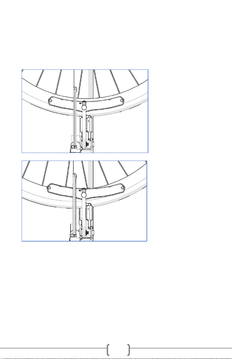
CONCENTRICITY
The Magnet Arrays should track the curve of the wheel when viewed
from the side. If the Magnet Arrays appear concentric, proceed to the
next section. If one end of the Magnet Array is higher/lower on the
brake track, follow these steps.
Concentric Magnet
Array
Non-concentric
Magnet Array
1. Slightly loosen both Mounting Bolts.
2. Adjust the mounting angle:
a. If the front end of the Magnet Array is low relative to
the brake rim, tighten the upper Mounting Bolt until the
Magnet Array comes into alignment.
b. If the front end of the Magnet Array is high relative to
the brake rim, tighten the lower Mounting Bolt until the
Magnet Array comes into alignment.
8
If a greater change in the mounting angle is necessary:
a. Further loosen the opposing Mounting Bolt.
b. Tighten both Set Screws to lift the Strain Gauge slightly
further away from the Frame.
c. Re-tighten the appropriate Mounting Bolt.
3. Ensure both Mounting Bolts are tight to secure the Resistance
Unit.
4. Re-check Concentricity and Height.
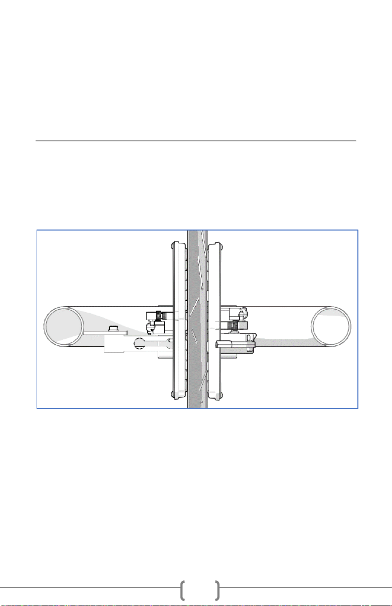
PARALLELISM
The space between the Magnet Array and your brake rim should be
even from the front end of the Magnet Array to the back.
If the Magnet Arrays appear parallel, proceed to the next section.
Parallel Magnet Array
If the Magnet Arrays are not perfectly parallel with the wheel (as seen in
the following diagrams), follow these steps.
1. Loosen Mounting Bolts slightly.
2. Use a 3mm Allen Key to adjust one of two Set Screws to change
the mounting angle.

9
a. If the Magnet Arrays skew right towards the front of the
bike when viewed from above, tighten the Set Screw
closer to the arm of the Frame.
b. If the Magnet Arrays skew left towards the front of the
bike when viewed from above, tighten the Set Screw
closer to the center of the trainer.
c. If you adjust the Set Screw too far in one direction on
your first attempt, resulting in the opposite parallelism
error, untighten the over tightened Set Screw slightly
before attempting to tighten the other one.
Tighten
Tighten

10
3. Re-tighten the Mounting Bolts.
4. Re-check Parallelism and Concentricity.
FINAL STEPS:
1. Re-align your Spoke Magnet with the tip of the Speed Sensor.
You are ready to ride!

11
POWERMETER SETUP AND CONFIGURATION
Support Video:
"Getting to know your Powermeter/Understanding the
Powermeter Lights"
Installation of Spoke Magnet and startup of Powermeter
1. Install the included spoke magnet on a drive side spoke.
2. Align the spoke magnet with the end of the Magnet Sensor
nearest the center of your wheel.
3. Adjust the Magnet Sensor within 5mm-10mm (¼”-½”) of the
spoke magnet. The red light on the Powermeter should toggle
on/off as the spoke magnet goes by.
4. Rotate the wheel a couple of revolutions slowly by hand to make
sure the spoke magnet will not hit your bike or the Magnet
Sensor.
5. Allow the unit to sit for 15 seconds after the Powermeter lights
have activated to allow for self-calibration.

12
[This page intentionally left blank]

13
[This page intentionally left blank]
14
Regulatory Compliance
Product: STAC Zero Powermeter
Model: Rigado BMD-300
FCC ID: 2AA9B04
IC: 12208A-04
European Compliance Statement
STAC Performance hereby declares that this device is in compliance with the
essential requirements and other relevant provisions of the R&TTE Directive.
FCC Compliance
This device complies with Part 15 of the FCC Rules. Operation is subject to the
following two conditions:
1) this device may not cause harmful interference, and
2) this device must accept any interference received, including interference
that may cause undesired operation.
Changes or modifications not expressly approved by STAC Performance, could
void the user’s right to operate the product.
This equipment has been tested and found to be compliant to FCC radiation
exposure limits. These limits are designed to provide reasonable protection
against harmful interference in a residential installation. This equipment
generates, uses, and can radiate radio frequency energy. If not installed and
used in accordance with the instructions, may cause harmful interference to
radio communications. However, there is no guarantee that interference will
not occur in a particular installation. If this equipment does cause harmful
interference, the user is encouraged to try to correct the interference with one
or more of the following measures
1) Reorient or relocate the receiving antenna
2) Increase the separation between the equipment and receiver
3) Connect the equipment into an outlet on a circuit different from that to
which the receiver is connected
4) Consult the dealer or an experienced radio/TV technician

15
For support go to:
www.staczero.com/support
For additional assistance, contact us at:
support@staczero.com
Looking for more speed on the bike?
Check out the STAC Virtual Wind Tunnel:
Improve your speed at your next race!
All the benefits of wind tunnel testing without the
cost and inconvenience of going to one.
Book your session today!
www.staczero.com/vwt
Follow us on social media:
@STACPerformance
This manual suits for next models
1
Table of contents


