STACKHAUS BUTLER SERIES User manual
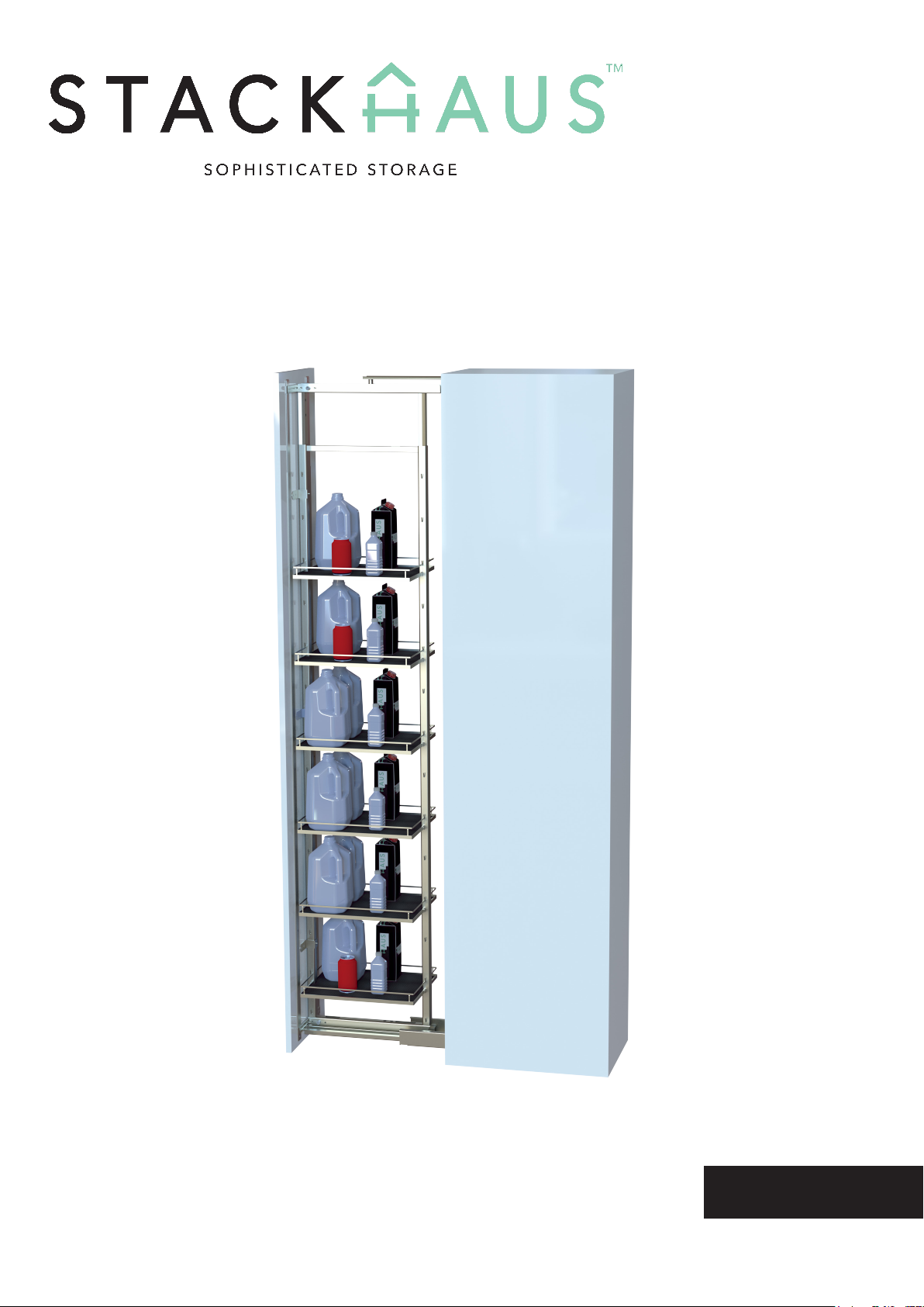
BUTLER SERIES TALL PANTRY
This is an example manual with mock assembly
procedures in three dierent languages.
User Manual
English

INTRODUCTION
WARNING
Introducing the Butler Series Tall Pantry assembly manual. In this manual, we will show you how
to assemble your own Butler Series Tall Pantry. Before beginning the assembly, make sure that
there is ample room for installing and assembling your product. The amount of Base Shelf Trays
with your assembly may also vary.
2
There is a maximum availalbe weight of 10 KG per shelf.
Some steps might require the assistance of two people.
Cabinet x1
Part 3 - T-Shaped Bracket
x1
Part 7 - Short Locker
Rail x1
3
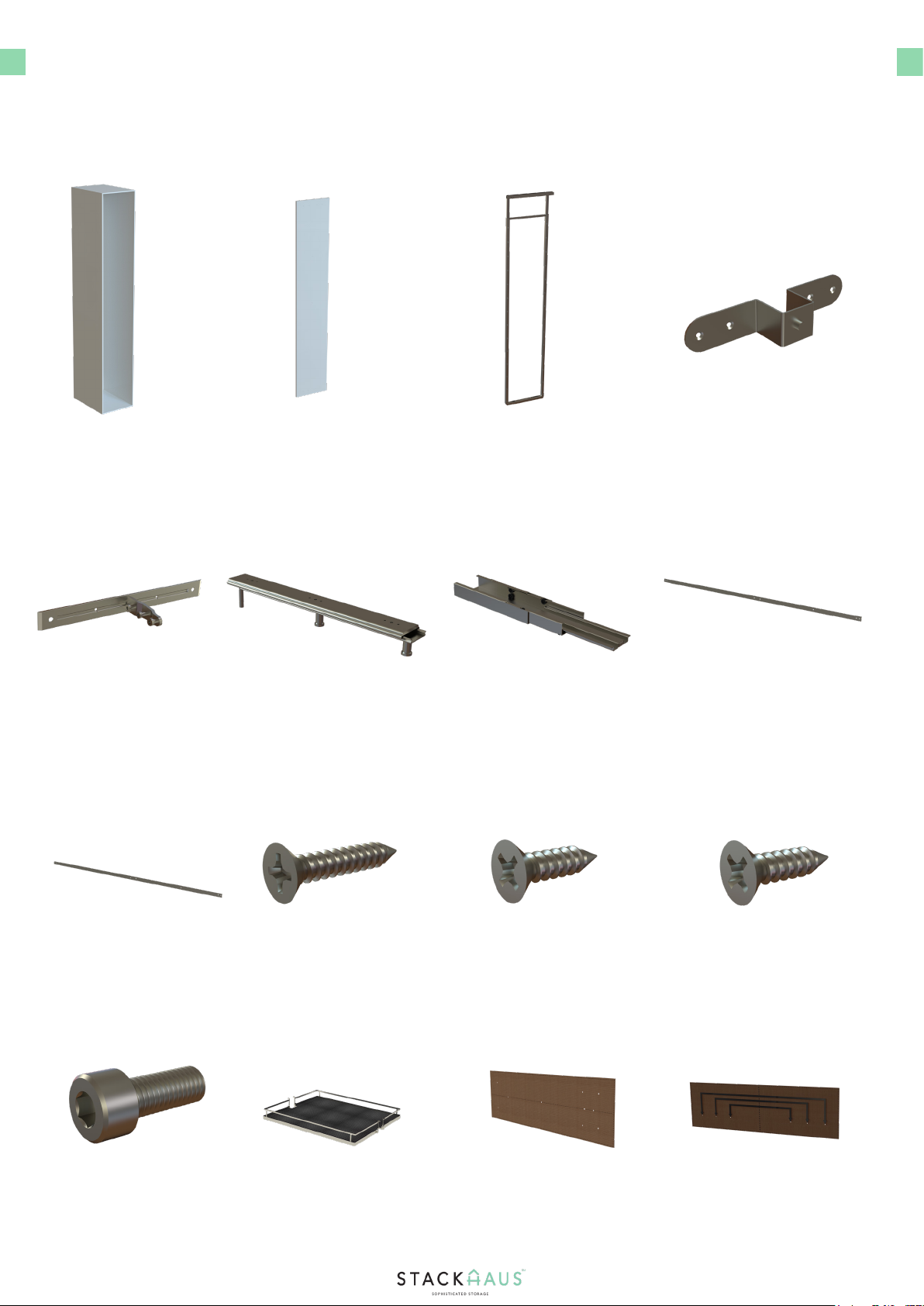
PARTS & TOOLS CHECK LIST
Ensure that the following parts are included with your sample bike. These are crucial
components that will be the mainframe of your entire assembly.
Cabinet x1 Part 2 - Bridge Shaped Bracket
x1
Part 5 - Lower Slider
x1
Cabinet Door x1
Part 3 - T-Shaped Bracket
x1
Part 6 - Long Locker Rail
x1
Part 1 -Main Frame
x1
Part 4 - Upper Slider
Bracket x2
Part 7 - Short Locker
Rail x1
Part 8 - ST 3.5 x 20
x8
Part 9 - ST 3.5 x 16 Screws
x30
Part 10 - ST 3.5 x 18
x11
Part 11 - M8 x 20
x2
Part 12 - Baskets
x6
Part 13 - Installation
Template x1
Part 13 - T-shaped
Installation Template x1
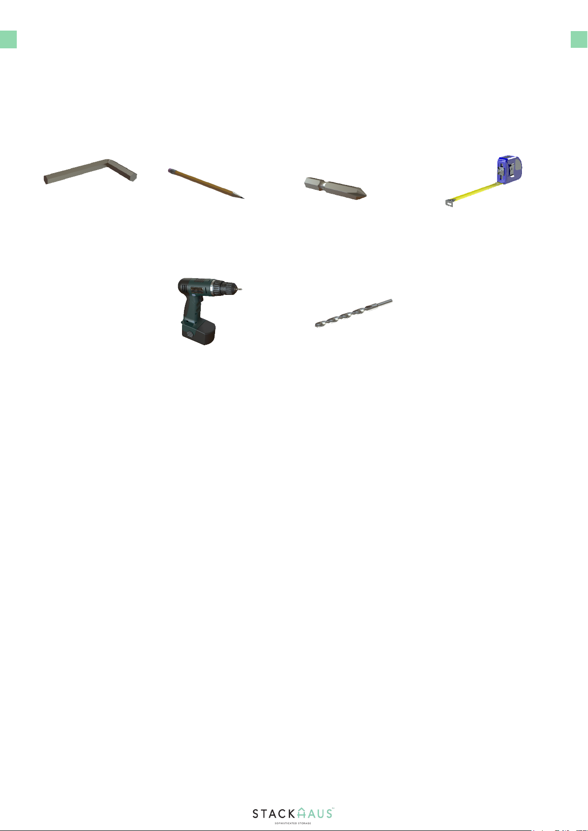
PARTS & TOOLS CHECK LIST
Ensure that the following parts are included with your sample bike. These are crucial
components that will be the mainframe of your entire assembly. Contact Customer Service
should there be inadequate quantities and if parts come damaged.
Pencil
x1
Tape Measure
x1
Allen Key
x1
Phillips Head Driver Bit
x1
2.5mm Drill Bit
x1
4
Power Drill with
Phillips Head Bit x1
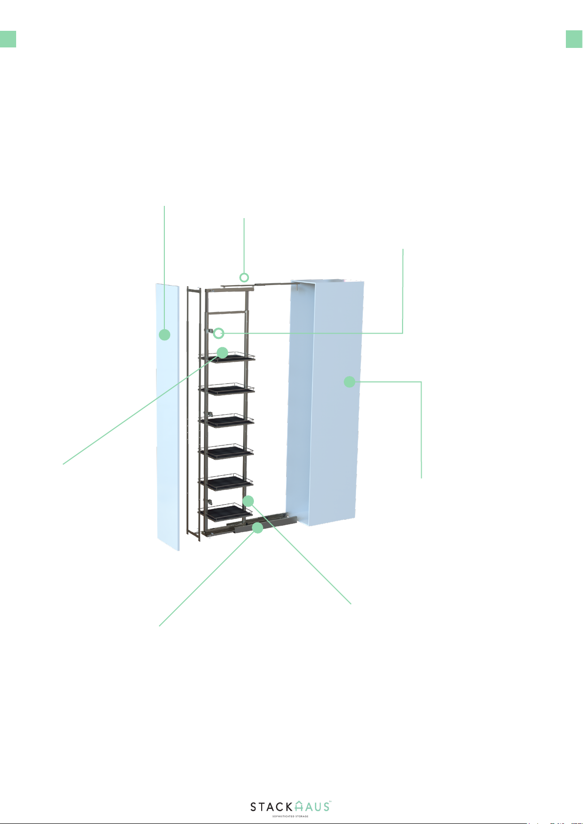
PARTS
5
Below is a breakdown of how the parts will come together for your nal product, as detailed in
the following steps.
Upper Slider
Door Panel
Main Frame
Assembly
Lower Slider
Base Shelf Trays
T-Shaped Brackets
Cabinet
Dimensions of your
cabinet may vary, but
should be within a set
average height. Please
refer to page 8 for
furhter information.
The amount of trays
vary from four to six
trays depending on
the model of your
cabinet.
Please refer to page 9
on how to adjust the
main frame.
Dimensions of your door
panel may vary, but
should match with the
general height of your
cabinet. Please refer to
pages 10 and 11 for fur-
ther information
This rail track will be
placed at the center
bottom of the inner
section of the cabinet.
Please refer to Page
7 for measurements
and specications.
This rail track will be
placed at the cen-
ter top of the inner
section of the cabinet.
Please refer to Page
7 for measurements
and specications.
There will be two
brackets that will be
placed on the spine of
the main frame and
will assist in securing
the door panel.
INSTRUCTIONS
6
Draw the line on the cabinet top
Place the installation template and pre-
drill holes
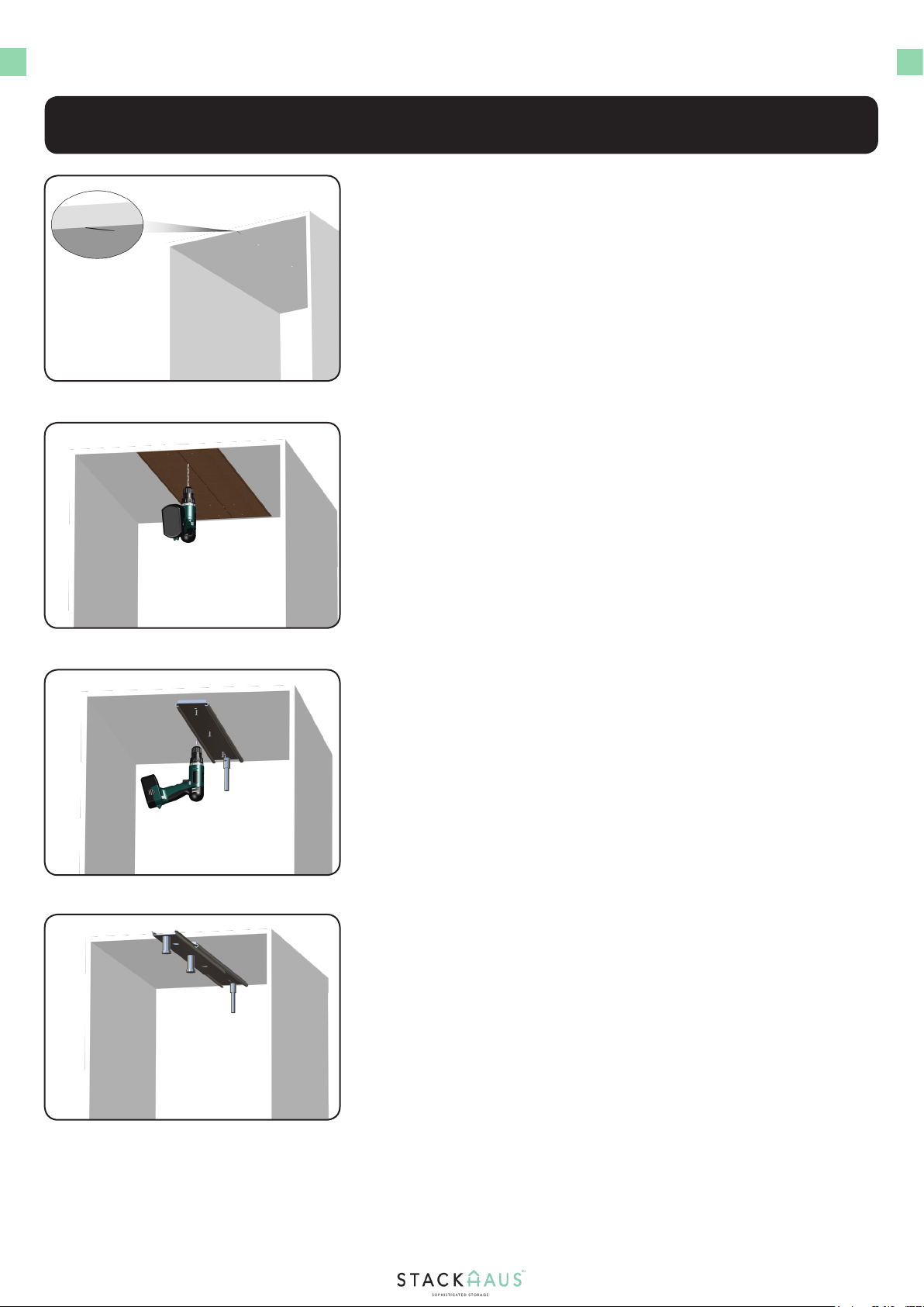
Begin Step One by using a pencil and drawing a central line
on the upper section of the cabinet. This will indicate the
starting point of applying the Part 13 Installation Template.
Next, line up the upper slider to match the holes drilled and
fasten to the upper section of the cabinet using four Part
Ten screws.
1.
3.
Step 1 - Installing the Upper Slider
Fasten the upper slider
Slide the rail back and forth
After splitting the installation in half, use the slider
installation template and place directly onto the area where
you marked, as shown. Once the template is placed, pre-
drill four 2.5mm holes using a drill bit. Keep the template
steady and intact to prevent misalignment.
Finally, once the upper slider has been secured, verify that
the upper slider is intact by sliding the rail back and forth to
ensure that there is no misalignment or loose movement of
the part.
2.
4.

Place the installation template and pre-
drill holes
INSTRUCTIONS
7
Draw the line on the cabinet bottom
Seperate the lower slider components
Next, seperate the components of the lower slider so
that the components are seperated, as shown. Set aside
the inner cover and sliding rail in a safe location for later
installation.
1.
3.
Step 2 - Installing the Lower Slider
Fasten the outer bracket of the lower
slider
With the lower slider installation template placed directly
onto the area where you marked, pre-drill six 2.5mm holes
using a drill bit. Keep the template steady and intact to
prevent misalignment.
Begin Step Two by using a pencil and drawing a central line
on the lower section of the cabinet. This will indicate the
starting point of applying the Part 13 Installation Template.
Finally, line up the lower slider to match the holes drilled
and fasten to the lower section of the cabinet using four
Part Ten screws.
2.
4.
DIMENSIONS
8
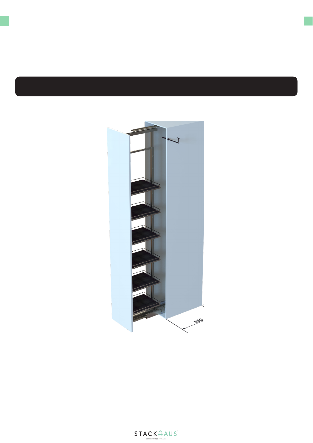
There are dierent sizes of your cabinet available. Depending on the height of your cabinet,
please refer to the dimensions down below to verify the adequate space needed to work with
installation
Rail Height and Main Frame Height
●The following image is a reference for the height of the rail and main frame.
The Space Series Tall Pantry comes in a variable range of height based on the dimensions shown in the right
hand table above in millimeters. Ensure that the rail, rail tracks, and main frame are of adequate height to
ensure proper installation. If there is not any adequate height for any of these parts, pleast contact customer
service at
INSTRUCTIONS
9
Place the frame on the lower slider component
Attach the frame to the upper slider
Slide out the upper rail, adjust the height of the main frame
accordingly so that the orientation of the main frame and
rail line up, then adjust and fasten the frame.
1.
3.
Step 3 - Installing and adjusting the frame
Install the inner cover and sliding rail of the low-
er slider
Slide the rails back and forth
Next, clean the lower slider before attaching the rail and
remaining components of the lower slider. Line up the main
frame to the upper and lower rails, as shown.
With the assistance of another person holding the main frame assembly
straight up, align the frame with the lower slider component so that the
bottom section of the assembly ts in with the middle section of the
component, as shown. Secure the frame to the component using two
Part 11 screws. Tighten the screws using an Allen Key
Finally, once the main frame has been secured to the rails,
slide the assembly back and forth to ensure that there is no
misalignment or loose movement of the parts.
2.
4.

INSTRUCTIONS
10
Mark and pre-drill holes according to template
Loosen the middle bolt of the T-shaped brackets
Before lining the door up with the main frame, loosen the
middle bolt and place in a safe location. This will be used to
secure the door assembly to the main frame.
1.
3.
Step 4 - Installing the Door
Install the locker rails and T-shaped brackets
Align the door assembly to the main frame
After drilling the holes and marking the locations, secure the long and
short locker rails to the door, as shown. The long locker rails will be
placed on the sides vertically while the short locker rails are placed
horizontally on the marked locations. Next, place the two T-shaped
brackets on top of the short rails, and secure the rails and brackets
using eighten Part 9 screws. Tighten the screws with a power drill.
Begin Step Four by locating the installation template for the T-shaped
bracket. As shown, mark the locations for the holes on the door, and
draw a line across accordingly. Two 2.5mm holes will drilled on the top
and bottom sections.
Align the door to the main frame and slide the components
until the components of both assemblies line up accordingly.
Once the parts have been aligned, use the previously
loosened bolts and re-insert the bolts to go through both
the main frame rails and the rails of the T-shaped bracket.
2.
4.
DIMENSIONS
11
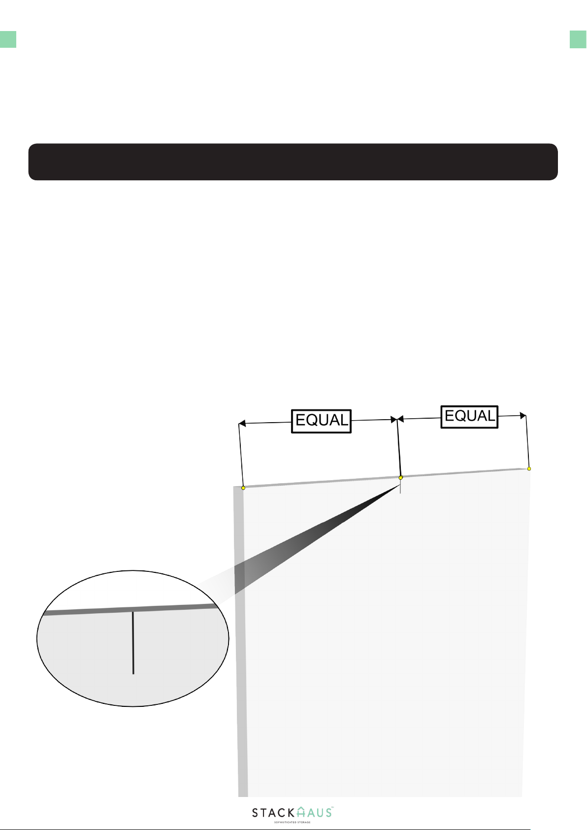
The back side of the door panel will have pre-drilled holes. Please refer to the image below for
specic dimensions and proper spacing so that installation of the door panel plastic brackets is
possible.
Door Panel Measurements
●The following image is a reference for the measurements of the door panel.
Using a tape measure, ensure that the spacing between each section of the holes of the door panel are of equal
distance, and that there are pre-drilled holes for installing your door panel plastic brackets.
INSTRUCTIONS
12
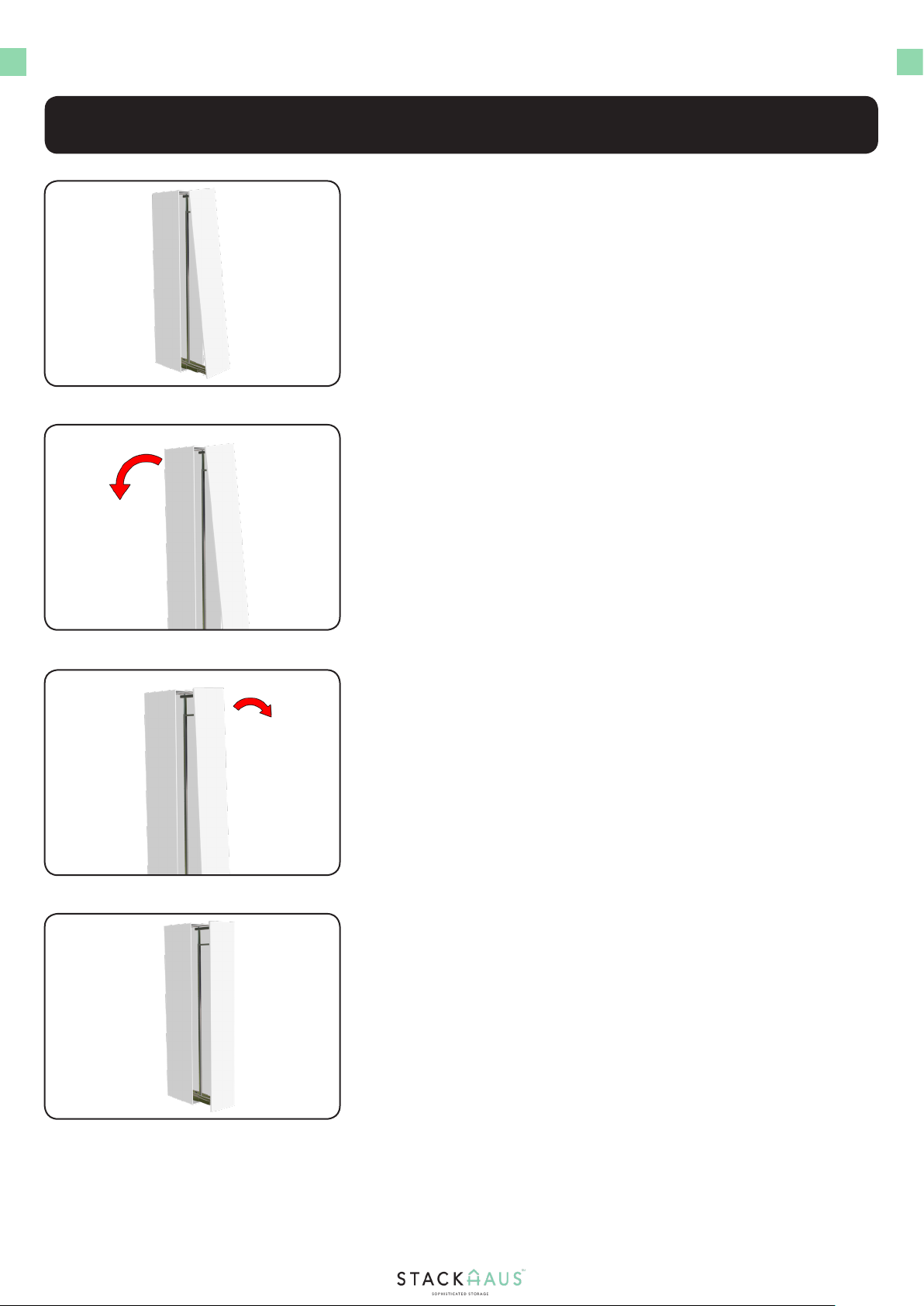
Adjusting the left & right incline
Right Incline procedure
1.
3.
Step 5 - Adjusting the Door
Left incline procedure
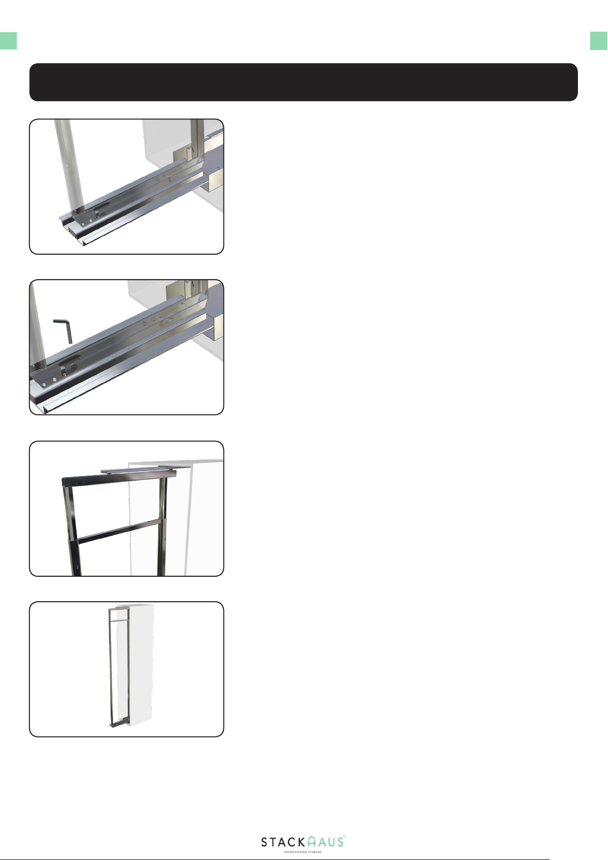
Slide the door and verify
Begin the left incline procedure by adjusting the top section of the
section where the main frame and rail of the T-shaped bracket are
conjoined. Screw the two smaller holes so that the door becomes
fastened to the main frame, and tighten the middle bolt.
Unscrew the bottom middle bolt, then unscrew the two side holes.
Once the the side holes are loosened, tighten the middle bolt again.
Adjust the top section of the section where the main frame and rail of
the T-shaped bracket are conjoined. Unscrew the middle bolt and two
holes, then tighten the middle bolt.
Screw the two side holes, then tighten the middle bolt.
Depending on the door, the door may have a left incline installation
procedure, a right incline installation procedure, or a procedure of both.
To ensure maximum stability of the door, it is crucial to adjust the door
accordingly by lossening, tightening, and adjusting the components of
the rail on the T-shaped brackets, as shown.
Verify that the door is tightly secured to the assembly by
sliding the door back and forth. Further loosening may be
required at the midsection of the two rails, as shown. If so,
simply use an Allen Key and readjust the previously installed
Part 11 screws.
2.
4.

INSTRUCTIONS
13
Line up the three bridge shaped brackets
Verify that all parts are secured
Once the baskets have been atttached, verify that all the
parts installed leading up to the baskets are properly
secured and any and all hardware are also properly secured
1.
3.
Step 6 - Attaching the Baskets
Attach the baskets
Slide the assembly back and forth to ensure baskets
are secured
Once the bridge shaped brackets have been installed, locate
the six baskets and line them up to the locations shown.
Depending on the model of your cabinet, the quantity of
baskets may vary.
Two people will be required for this step. Begin by aligning the three
bridge shaped brackets to the locations, as shown. Using a power drill,
secure the bridge shaped brackets to the door using a total of twelve
Part 9 screws. Take care not to over tighten the screws.
Slide the door back and forth to ensure no misalignment
or unwanted movement occurs. Once you have veried
the door seamlessly motions back and forth, you have
completed the assembly of the Butler Series Tall Pantry.
2.
4.

Other manuals for BUTLER SERIES
1
Table of contents
Other STACKHAUS Indoor Furnishing manuals


Popular Indoor Furnishing manuals by other brands


URBAN OUTFITTERS
URBAN OUTFITTERS DINA STOOL Assembly instructions

meubar
meubar JODHPUR DR8 Assembly instruction

Kesseböhmer
Kesseböhmer TopFlex Mounting instructions

Dorel Living
Dorel Living DA010-SF Instruction booklet

Costway
Costway JV10341 manual

Mocka
Mocka Milton Tall Plant Stand Assembly instructions