STACKHAUS SPACE Series User manual
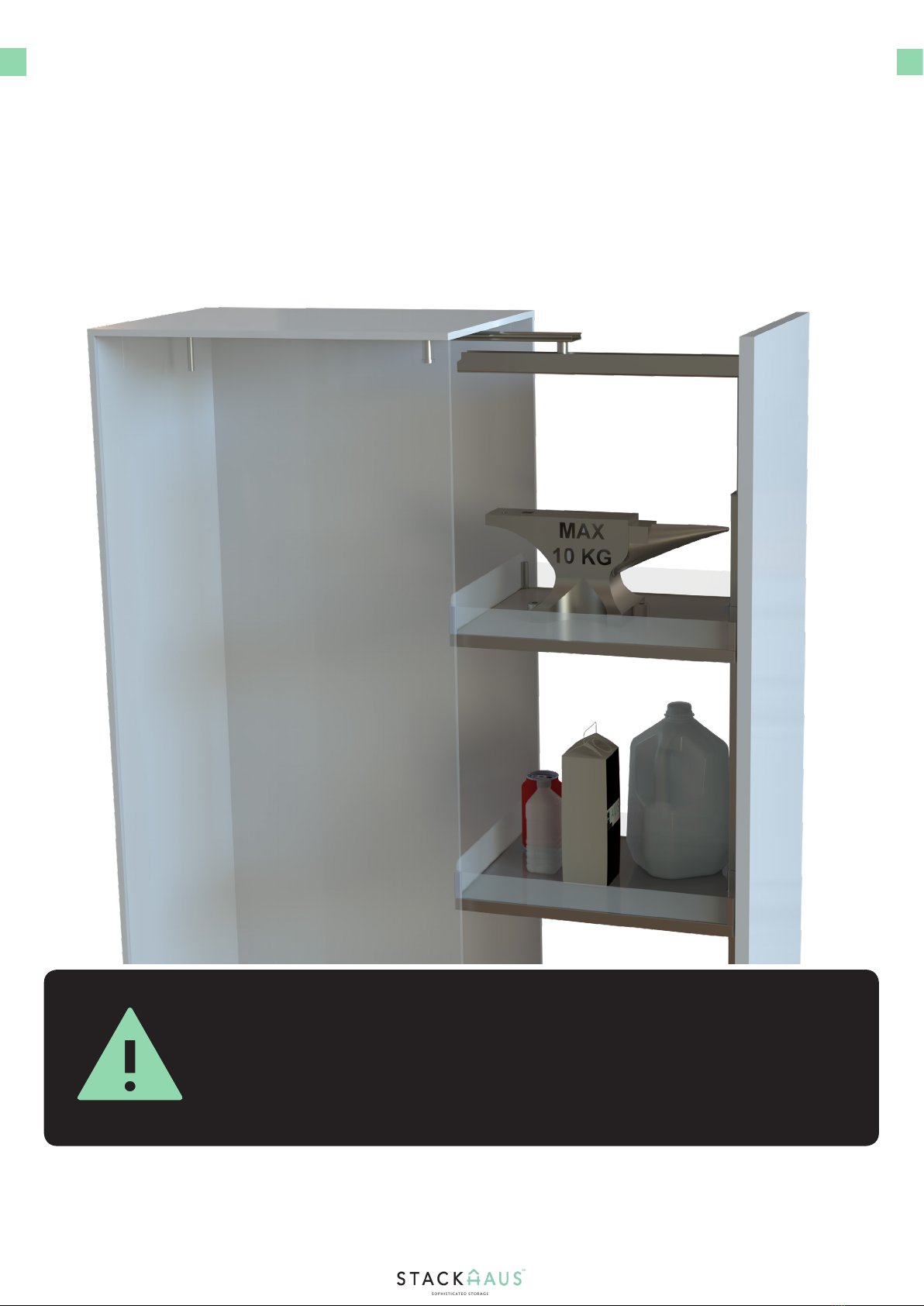
SPACE SERIES TALL PANTRY
User Manual
English
Scan for Setup Video

INTRODUCTION
WARNING
Introducing the Space Series Tall Pantry assembly manual. In this manual, we will show you how
to assemble your own Space Series Tall Pantry. Before beginning the assembly, make sure that
there is ample room for installing and assembling your product. The amount of Base Shelf Trays
with your assembly may also vary.
2
There is a maximum availalbe weight of 10 KG per shelf.
Some steps might require the assistance of two people.
Cabinet x1
Part C - Large Guide
Rail Track x1
Part G - Main Frame
Stand x1

3
PARTS & TOOLS CHECK LIST
Ensure that the following parts are included with your sample bike. These are crucial
components that will be the mainframe of your entire assembly.
Cabinet x1 Part B - Bottom Cover
x1
Part E - Adjustable
Connecting Rail x1
Door Panel x1
Part C - Large Guide
Rail Track x1
Part F - Lower
Connecting Rail x1
Part A - Upper Rail Track
x1
Part D - T Shaped
Bracket x2
Part G - Main Frame
Stand x1
Part H - Base Shelf
Tray x4-6
Part L - ST 3.5 x 16
x13
Part M - M6 x 25
x1
Part N - M6 x 12
x2
Part Q - ST 3.5 x 20
x8
Part O - M8 x 20
x2
Part P - Hexagonal Insert
x1

PARTS & TOOLS CHECK LIST
Ensure that the following parts are included with your sample bike. These are crucial
components that will be the mainframe of your entire assembly. Contact Customer Service
should there be inadequate quantities and if parts come damaged.
Part T - Allen Key K5
x1
Phillips Screwdriver
x1
Power Drill
x1
Part R - M6x12
x6
Part U - Door Panel
Plastic Wrench x3
Pencil
x1
Tape Measure
x1
Part S - Allen Key K4
x1
Part V - Washers
x4
Phillips Head Driver Bit
x1
4

These will help further
secure the door panel.
Please refer to page
13 for adjusting these
parts.
PARTS
5
Below is a breakdown of how the parts will come together for your nal product, as detailed in
the following steps.
Door Panel
Plastic Wrenches
Upper Rail Track
Door Panel
Main Frame
Assembly
Large Guide
Rail Track
Base Shelf Trays
T-Shaped Brackets
Cabinet
Dimensions of your
cabinet may vary, but
should be within a set
average height. Please
refer to page 8 for
furhter information.
The amount of trays
vary from four to six
trays depending on
the model of your
cabinet.
Please refer to page 9
on how to adjust the
main frame.
Dimensions of your door
panel may vary, but
should match with the
general height of your
cabinet. Please refer to
pages 10 and 11 for fur-
ther information
This rail track will be
placed at the center
bottom of the inner
section of the cabinet.
Please refer to Page
7 for measurements
and specications.
This rail track will be
placed at the cen-
ter top of the inner
section of the cabinet.
Please refer to Page
7 for measurements
and specications.
There will be two
brackets that will be
placed on the spine of
the main frame and
will assist in securing
the door panel.

INSTRUCTIONS
6
Place Part G Frame Stand at on the ground
Attach Part F Adjustable Connecting Rail
With Part G at on the ground, locate the end holes wher
Parts E and F will be inserted. The end where Part E will go
will only have two holes on the spine while the end where
Part F goes will have six holes, two on the spine and two on
each side.
Next, locate Part F Adjustable Connecting Rail. Secure Part
F frame using six Part R bolts and four Part V washers. Two
washers and bolts are to be placed on the sides of the main
frame rail, and two bolts are to be placed in the center of
the rails. Tighten the bolts using the provided K5 Allen Key,
Part T.
1.
3.
Step 1 - Main Frame Assembly
Attach Part E Adjustable Connecting Rail
Attach Part F Adjustable Connecting Rail
Start the assembly by locating the Part E Adjustable
Connecting Rail. Secure Part E rail using two Part R bolts.
Tigthen the bolts using a Phillips screwdriver. Take care not
to over tighten the bolts. Leave the bolts semi-loose.
Next, locate Part F Adjustable Connecting Rail. Secure Part
F frame using six Part R bolts and four Part V washers. Two
washers and bolts are to be placed on the sides of the main
frame rail, and two bolts are to be placed in the center of
the rails. Tighten the bolts using a Phillips screwdriver.
2.
4.

INSTRUCTIONS
7
Installing Part A Upper Rail Track
Installing Part C
Next, Part C will be placed in the center of the bottom base
with a spacing of approximately 25 millimeters from the
open cabinet end.
1.
3.
Step 2 - Installing the Rail Tracks
Securing Part A
Securing Part C
Slide out the rail of Part A and secure it using four Part L
screws. With the assitance of another person keeping Part
A in place, tighten the screws using a power drill with a
Phillips head driver bit, taking care not to overtighten and
keeping the rail intact.
Begin by placing the Part A Upper Rail Track on to the inner
cabinet roof top. Part A will be placed in the center of the
inner cabinet roof top with a spacing of approximately 74
millimeters from the open cabinet end.
Slide out the rail of Part C and secure it using six Part L
screws. With the assitance of another person keeping Part
C in place, tighten the screws using a power drill with a
Phillips head driver bit, taking care not to over tighten and
keeping the rail intact.
2.
4.

DIMENSIONS
8
There are dierent sizes of your cabinet available. Depending on the height of your cabinet,
please refer to the dimensions down below to verify the adequate space needed to work with
installation
Rail Height and Main Frame Height
●The following image is a reference for the height of the rail and main frame.
The Space Series Tall Pantry comes in a variable range of height based on the dimensions shown in the right
hand table above in millimeters. Ensure that the rail, rail tracks, and main frame are of adequate height to
ensure proper installation. If there is not any adequate height for any of these parts, pleast contact customer
service at

INSTRUCTIONS
9
Attach Main Frame Assembly to Part C
Installing Part C
After the bolts are loose, raise the top section of the
assembly so that the sucient height is necessary to attach
to the Part A rails, as shown. Reattach the bolts once the
upper section has been attached to Part A.
1.
3.
Step 3 - Attaching the Main Frame Assembly
Loosen the top section
Securing Main Frame Assembly
Next, using a Philips screwdriver, loosen the bolts on the
top section of the main frame assembly so that the top
section can be raised up.
With the assistance of another person holding the main frame assembly
straight up, align the Main Frame Assembly with Part C so that the
bottom section of the assembly ts in with the middle section of Part C,
as shown. Secure the Main Frame Assembly to Part C using two Part O
bolts, and one Part P Hexagonal Insert.Tighten the bolts and the Part P
insert using the provided K4 Allen Key, Part S.
Once the main frame assembly is secured, verify that all
hardware has been secured and that the newly combined
assembly adequately slides in and out.
2.
4.

INSTRUCTIONS
10
Place the door panel on a at surface
Securing the Part U brackets
After attaching the Part U brackets, secure the Part U
wrenches to the door using three Part L screws.
1.
3.
Step 4 - Assembling the Door Panel
Attach three Part U brackets
Tightening the screws
Matching the three center holes of the door panel, attach
three Part U Door Panel Plastic Brackets to the cabinet door.
Begin Step Four by locating the door panel of the assembly and laying
it at on a leveled surface with the back side facing up. There are pre-
drilled holes on the cabinet door. Matching the three center holes of
the Door, Attach three Part U Door Panel Plastic Brackets to the cabinet
door. For dimensions and spacing of the holes, please refer to the next
page.
Tighten the screws using a power drill with a phillips head
drill bit. Repeat these steps for the remaining screws.
2.
4.

DIMENSIONS
11
The back side of the door panel will have pre-drilled holes. Please refer to the image below for
specic dimensions and proper spacing so that installation of the door panel plastic brackets is
possible.
Door Panel Measurements
●The following image is a reference for the measurements of the door panel.
Using a tape measure, ensure that the spacing between each section of the holes of the door panel are of equal
distance, and that there are pre-drilled holes for installing your door panel plastic brackets.

INSTRUCTIONS
12
Line up the two Part D T-shaped brackets
Securing the Part D T-shaped brackets
Ensure that the Part D T-Shaped brackets are aligned to the
side holes and are locked into place.
1.
3.
Step 5 - Attaching the T-Shaped Brackets
Attach the two Part D T-shaped brackets
Check the Part D T-Shaped brackets
Insert both Part-D T-Shaped brackets into the top and
bottom of the main frame assembly, until the T-shaped
brackets lock into place.
Locate the two Part D T-shaped brackets, and line them up to the top
and bottom sections of the main frame assembly. The frames will be
inserted through the holes.
Verify that both top and bottom Part D brackets are correctly
placed in the allocated spots and remains intact on the rail.
2.
4.

INSTRUCTIONS
13
Line up the two Part D T-shaped brackets
Secure the door to the top Part D T-shaped bracket
Secure both T-Shaped Part D Brackets, using four Part Q
screws each. Tighten the screws using a power drill with a
phillips head drill bit.
1.
3.
Step 6 - Attaching the Door to the Main Frame Assembly
Adjust the door panel plastic wrenches
Secure the door to the bottom Part D T-shaped
bracket
Before attaching the cabinet door to the main frame, adjust
the door panel plastic wrenches by turning the handles
counter-clockwise, as shown. Repeat this motion for the
remaining plastic wrenches
Two people will be required for this step. Begin by placing the previously
assembled cabinet door assembly onto the main frame assembly.
Repeat these steps for the bottom Part D T-shaped bracket.
Verify that the door is secured and that the rail tracks slide
back and forth with ease.
2.
4.

INSTRUCTIONS
14
Line up the Part B Low Frame Cover
Use a Phillips Screwdriver
Tighten the screw using a Phillips screwdriver. Take care
not to over tighten the screw, as adjustments to the frame
may be required in a later step.
1.
3.
Step 7 - Attaching the Bottom Frame Cover
Securing the Part B Low Frame Cover
Verify the Part B Low Frame Cover is secured
Once the Part B Low Frame Cover is locked into place,
secure it to the lower rail using one Part M Screw.
Locate the Part B Low Frame Cover. Place Part B over the
lower rail, slide it, and lock it into place.
Slide the door back and forth to ensure that the low frame
cover is properly secured.
2.
4.

INSTRUCTIONS
15
Line up the Part H Base Shelf Tray
Attach the remaining Part H trays
Next, repeat these steps for the remaining trays. The
number of trays vary per desired height, typically 4 to 6
trays can be used.
1.
3.
Step 8 - Attaching the Shelf Trays
Adjusting the clip of the tray
Verify that the Part H Trays are secured
Push the tray into place, and secure it by adjusting the clip
on the tray. To lock the tray into place, simply adjust the clip
90 degrees to line up with the railing and then lock the tray
into place.
Locate one Part H Base Shelf Tray. The Part H tray is to be
attached to the corresponding bottom section of the rail.
Before attaching the tray to the rail, make sure the clip is
pushed downward towards you.
Slide the door back and forth to ensure that the trays are
intact and that they do not fall o the assembly.
2.
4.

INSTRUCTIONS
16
Locate the bottom of the main frame assembly
Verify all parts and hardware are secure
Ensure that no parts and hardware are loose and that the
rails are free of any obstruction that would cause any jam
to the motion of the door and rails.
1.
3.
Step 9 - Tightening and Adjusting the Door Panel
Tighten the bolts
Slide the door back and forth to ensure usage
Using the provided Part S K4 Allen Key, tighten bolts and
following hardware if needed to adjust the panel if it does
not t properly.
Temporarily remove the Part B Low Frame Cover from Step
7 so that access to the inner bolts is possible, should you
need to adjust the door panel.
Once verication of all parts and hardware are secure,
slide the door back and forth to ensure that the rails are
working properly. Congratulations, you have completed the
assembly of the Space Series Tall Pantry!
2.
4.
Table of contents
Other STACKHAUS Indoor Furnishing manuals
Popular Indoor Furnishing manuals by other brands

pottery barn kids
pottery barn kids CAROLINA Important safety and assembly instructions

fantastic furniture
fantastic furniture STOCKHOLM LOWLINE MEDIUM 1600MM manual

Charlies
Charlies CRG948 manual

Hudson & Canal
Hudson & Canal TV1478 Assembly instructions

atmosphera
atmosphera ARTY 166743 manual

Hillsdale Furniture
Hillsdale Furniture STACI 1525-010 manual

John Lewis
John Lewis Calia 836 03001 Assembly instructions

Seville Classics
Seville Classics AirLift instructions

CALIMA
CALIMA 46042 operating instructions

Trinity
Trinity TXKPGR-0501 owner's manual

NetSuite
NetSuite ARLO-GREY-FB-HB/FB + Assembly instructions

ROBERTO FIORE
ROBERTO FIORE CABINETS TO GO BC09 Assembly instructions