STACKHAUS MAGIC CORNER PRO User manual

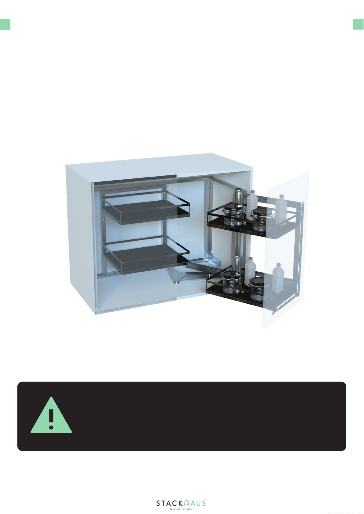
MAGIC CORNER PRO
User Manual
English
Play Setup Video
INTRODUCTION
WARNING
Introducing the Magic Corner Pro assembly manual. In this manual, we will show you how to
assemble your own Magic Corner Pro. Before beginning the assembly, make sure that there
is ample room for installing and assembling your product. Please check the following chart to
ensure the product size exactly suits your cabinet based on the following dimensions.
2
The maximum load capacity of the Magic Corner Pro is 25 kg, with each
basket having a maximum load capacity of 6kg. It is highly recommened
to not exceed the maximum load capacity of the product and the items
contained in it to prevent possible damage.
3
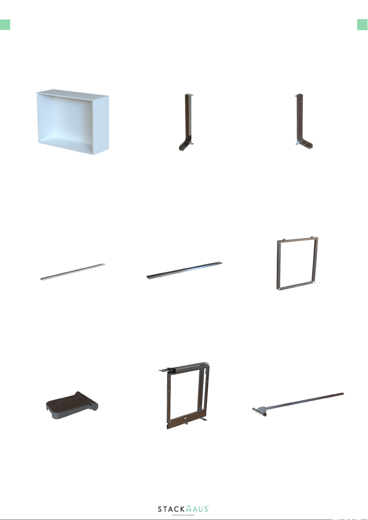
PARTS & TOOLS CHECK LIST
Ensure that the following parts are included with your Magic Corner Pro. These are crucial
components that will be the mainframe of your entire assembly. The following tools are
recommended for this installation.
Cabinet x1 Part 1a x1 Part 1b x1
Part 2b x1 Part 3 x1
Part 6 x1
Part 2a x1
Part 4 x1 Part 5 x1

4
PARTS & TOOLS CHECK LIST
Ensure that the following parts are included with your Magic Corner Pro. These are crucial
components that will be the mainframe of your entire assembly. The following tools are
recommended for this installation.
Part 7 x1 Part 8a x1 Part 8b x1
Part 10 x32
Part 13 x2
Part 11 x1
Part 9 x1
Part 12 x2
Power Drill with
Phillips Screwdriver x1
Power Drill with
Phillips Head Bit x1

PARTS
Below is a breakdown of the core parts for your nal product, as detailed below.
Part 7
Magic Corner
Pro Rails
Baskets
Dimensions of your
cabinet may vary, but
should be within a set
average height. Please
refer to the next page
for furhter information.
Part 7 is essential for
the Magic Corner Pro’s
functionality of opening
and closing the com-
partment.
The rail components
of the Magic Corner
Pro is crucial for the
foundation of the
nal product once
attached to your
cabinet.
5

6
INSTRUCTIONS
Measure your cabinet accordingly
Begin Step One by locating the cabinet and measuring out
the dimensions of the cabinet so that you can properly
install the Magic Corner Pro that best suites your cabinet’s
measurements.
1.
Step 1 - Checking the Cabinet Size
The dimensions of the Magic Corner Pro are listed below. The measurements of the cabinet
shown below are a minimum and does not necessarily reect the nal product’s dimensions.
Please ensure that proper measurements have been recorded so that you can determine the
proper lifter that best suits your cabinet.
Magic Corner Pro Measurements

Place the drilling template
INSTRUCTIONS
Locate the drilling template
Pre-drill the holes on the template
Drill eleven holes using a power drill with a 2.5mm drill bit,
matching the locations of the template.
1.
3.
Step 2 - Aligning the Drilling Template
Place the drilling template to the side of the cabinet, as
shown, and fold out the driling template to cover the specied
areas shown on the template, and match accordingly.
Begin Step Two by locating the Drilling Template and place it
in the location you wish to pre-drill the holes. The template
can be used to align for a left sided orientation, or a right
sided orientation, depending on your preference.
2.
7

INSTRUCTIONS
Locate the inner frame components
Align Part 3 into place
Locate Part 3 and push it into place with the newly formed
assembly. Make sure that the wheels on Part 3 slide into
place and moves back and forth accordingly.
1.
3.
Step 3 - Installing the Inner Frame
Snap the Part 4 components into place
Align Part 1a to the assembly
Secure the assembly to the cabinet
Next, snap both Part 4 components into place to secure the
Part 2a and Part 2b components to Part 1b
Begin Step Three by locating the inner frame components ( one Part
1b, one Part 2a, one Part 2b, and two Part 4 ) and attach them in the
orientation shown.
Finally, align Part 1a and two more additional Part 4
components and secure them to the assembly, as shown.
Finally, secure the assembly to the cabinet, as shown. Drill
a total of eight Part 10 screws into the following locations.
The image on the left is for the right side alignment. For
the left side alignment, simply drill the two screws on the
opposite upper left corner.
2.
4.
5.
9
INSTRUCTIONS
Locate the Part 5 and Part 6 components and se-
cure together
1.
Step 4 - Installing the Side Swivel Frame
Extend the frame outward and align the newly
formed assembly
Secure the assembly
Secure the remaining holes of the assembly
Extend the frame outward, as shown, so that the bar extends outward.
Align the newly formed assembly to the cabinet so that it aligns with the
side panel and pre-drilled holes from Step 2 of the cabinet that matches
your preferred orientation.
Secure the assembly using three Part 10 screws. Tighten the screws
using a Power Drill with a Phillips Head Drill bit. Take care not to over
tighten the screws.
Ensure that all the remaining pre-drilled holes are aligned and secured
accordingly to fully secure the assembly.
Begin Step Four by locating the Part 5 and Part 6 components and align
them, as shown. Secure the Part 6 component using one Part 10 screw.
2.
3.
4.

INSTRUCTIONS
10
Locate the Spinning Bottom Part
Continue securing Part 7 to the thin holed rail
Secure the center of Part 7
1.
3.
3.
Step 5 - Installing the Spinning Bottom Part
Secure Part 7 to the wheeled section
To secure Part 7, rst have the wheel from the previous assembly align
with the wider curved end of Part 7, and push downwards and then
towards the center of Part 7 .
Proceed to align the thinner section of Part 7 to the thin holed section
of the rail assembly and securely push the section into place into the
hole. Place the nub of the thin section into the furthest hole applicable
, depending on your cabinet dimensions.
Finally, secure the center of Part 7 using four Part 10 screws. Tighten
the screws using a Power Drill with a Phillips Head Bit. Take care not to
over tighten the screws.
Locate the Part 7 component and aling it to the bottom of the assembly
from the previous step. Make sure that Part 7 is aligned accordingly to
ensure proper functionality of the product.
2.

INSTRUCTIONS
11
Locate the Cabinet Door and drilling template
Secure Part 8a or 8b to the Cabinet Door
Attach the cabinet door to the main component
1.
3.
4.
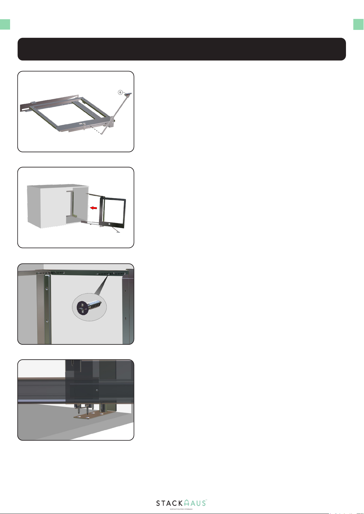
Step 6 - Attaching the Cabinet Door
Locate and align Part 8a or 8b
Next, locate and align Part 8a to the pre-drilled holes so that the holes
match that with Part 8a. If you are opting with a left-hand opening, use
Part 8b, instead.
Secure Part 8a or 8b to the cabinet door using nine Part 10 Screws.
Tighten the screws using a power drill with a Phillips Head bit. Take care
not to over tighten the screws. Repeat these steps for the remaining
screws.
With the newly formed cabinet door assembly, attach it to the main
component rails in the location shown and simply push downward until
the door snaps into place.
Locate the Cabinet Door, and align the Drilling Template to the cabinet
door, as shown. Depending on your preference, you can install the
door to open from the right side, or open from the left side. Pre-drill
nine holes using a Power Drill with Drill Bit, and remove the template
afterwards. For
2.

INSTRUCTIONS
12
Locate Part 9 and push into place
2.
Step 6 - Attaching the Cabinet Door
Push Part 6 into the grooved section
Next, push Part 6 into the grooved section of the cabinet door so that it
snugly ts into place.
Locate one Part 9 piece and push downward so that it snaps into place
and secures the lower extending rail section from the main frame, as
shown.
1.

INSTRUCTIONS
13
Step 7 - Adjusting the Cabinet Door
Adjust the cabinet door
1.
You can adjust the cabinet door by loosening up the screws shown
in the following locations and move the cabinet door left, right, back
and forth, and up and down until proper alignment is achieved. Use
a Phillips screwdriver to loosen and tighten the screws to keep the
desired adjustment.
INSTRUCTIONS
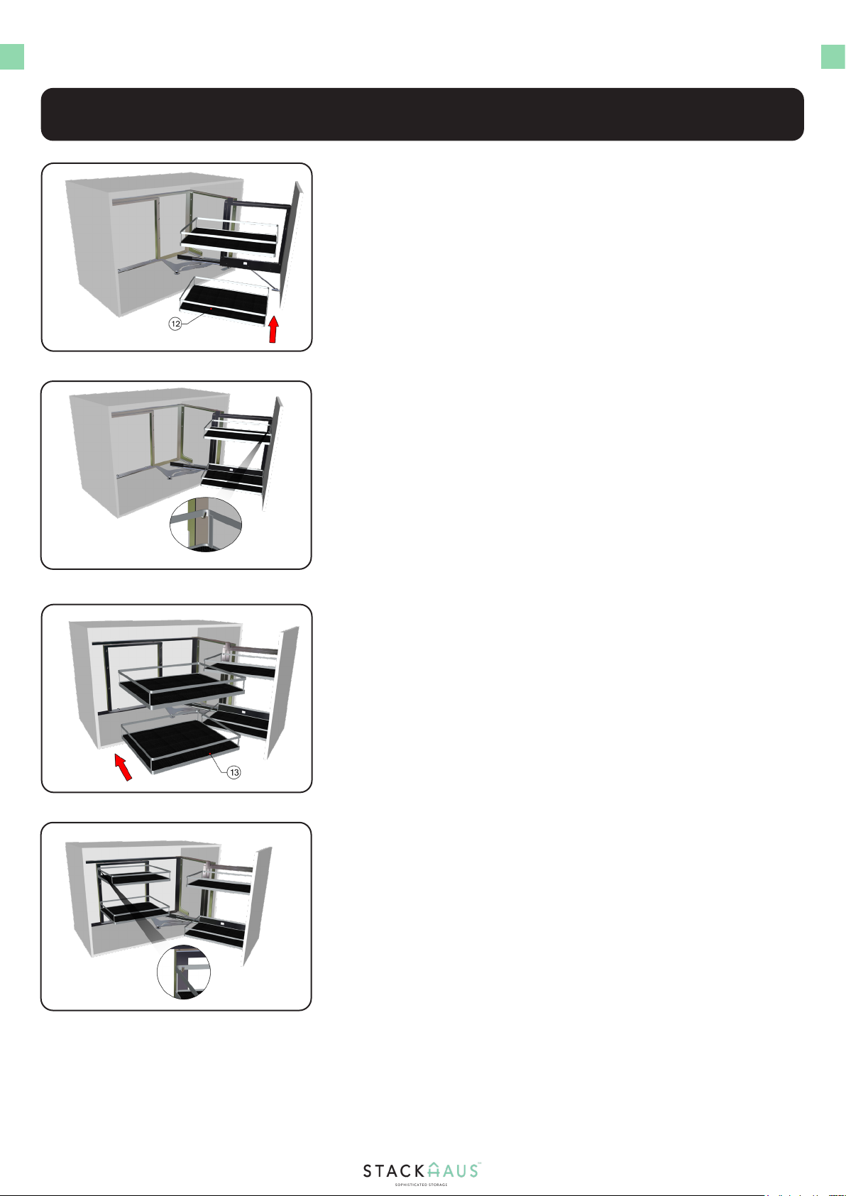
14
Attach the baskets and secure on the hooks
Attach the baskets and secure onto the hooks
2.
2.
Step 6 - Installing the Baskets
Locate two Part 12 baskets
Locate two Part 13 baskets
Locate two Part 12 baskets and align them to the following locations
shown
Next, locate two Part 13 baskets and aligne them to the interior section
of the cabinet shown.
Attach the baskets onto the hooks and slowly push into place. Adjust
the necessary height as needed for each basket.
Attach the baskets onto the hooks and slowly push into place. Adjust
the necessary height as needed for each basket. Once all baskets are
attached, installation is now complete.
1.
1.

Table of contents
Other STACKHAUS Indoor Furnishing manuals


Popular Indoor Furnishing manuals by other brands

Mocka
Mocka Claremont Entertainment Unit Assembly instructions

Furinno
Furinno 11205 Assembly instruction

Leisuregrow
Leisuregrow LG OUTDOOR Barcelona Assembly and care instructions

La Redoute INTERIEURS
La Redoute INTERIEURS SEMEON 4624360 quick start guide

Politorno
Politorno MALTA 1171 Assembly instructions

DREAMS
DREAMS Cooper Ottoman King Bed Assembly instructions


