Staco Energy StacoVAR User manual

Together We Power On
003-2703 REV A
StacoVAR
Power Factor Correction
USER MANUAL

Page | ii
No reproduction of any part of this manual, even partial, is permitted without the authorization of Staco
Energy Products Company. The Staco Energy Products Company reserves the right to modify the
product described herein, in order to improve it, at any time and without notice.
2425 Technical Drive • Miamisburg, Ohio 45342
U.S. Toll Free 866-261-1191
(937) 253-1191 • Fax: (937) 253-1723
Web site: www.stacoenergy.com
Thank you for choosing our product.
Staco Energy is highly specialized in the development and production of power factor correction
systems (PFC). The PFC’s of this series are high quality products, carefully designed and
manufactured to ensure optimum performance.
Page | iii
Safety Warnings
IMPORTANT SAFETY INSTRUCTIONS
SAVE THESE INSTRUCTIONS
Symbols used in the Manual
In this manual, some operations are shown by graphic symbols to alert the reader to the dangerous
nature of the operations:
Danger / Risk of Electric Shock
This symbol indicates possibility of serious injury or substantial
damage to the unit unless adequate precautions are taken.
Warning
This symbol indicates important information which must be
understood and any stated precautions taken
Note
Protective Equipment
No maintenance operations shall be conducted on the unit without wearing the Personal Protective
Equipment (PPE) described below. Personnel involved in the installation or maintenance of the unit must
be properly clothed.
The following signs show the protective equipment that should be worn. The various items of PPE must
be selected and sized according to the nature of the hazard (particularly electrical) posed by the unit.
Accident
prevention
footwear
Protective eyewear
Protective
clothing
Helmet
Work gloves

Page | iv
GENERAL PRECAUTIONS
This manual contains detailed instructions for the use, installation, and start-up of the PFC. Read the
manual carefully before installation. For information on using the PFC, the manual should be kept close
at hand and consulted before carrying out any operation on the PFC.
This PFC has been designed and manufactured in accordance with the standards for the product,
for normal use and for all uses that may reasonably be expected. It may under no circumstances
be used for any purposes other than those envisaged, or in any other ways than those described
in this manual. Any interventions should be conducted in accordance with the criteria and the
timeframes described in this manual.

Page | v
Table of Contents
Safety Warnings ......................................................................................................................................iii
1. General Description ............................................................................................................................. 1
1.1 Layout ............................................................................................................................................ 1
1.2 Components ................................................................................................................................... 4
2 Safety Instructions ................................................................................................................................ 5
3. Installation............................................................................................................................................ 5
3.1 Placement of the CT....................................................................................................................... 6
3.2 CT Connection................................................................................................................................ 7
3.3 Connection to Utility........................................................................................................................ 8
4. PQC Operation .................................................................................................................................... 8
4.1 User Interface................................................................................................................................. 8
4.2 Password Protection....................................................................................................................... 9
4.3 Output Relays (Control outputs) ..................................................................................................... 9
4.4 Alarm Contact............................................................................................................................... 10
5. Initial Start-up..................................................................................................................................... 10
5.1. Start-Up....................................................................................................................................... 10
5.2 Auto Commissioning..................................................................................................................... 10
6. Display Operation .............................................................................................................................. 11
6.1 Display Menus .............................................................................................................................. 12
6.1.1 PFC menu.............................................................................................................................. 12
6.1.2 System & PQ ......................................................................................................................... 13
7. Alarms ............................................................................................................................................... 15
7.1 Alarm Management ...................................................................................................................... 15
7.2 List of Alarms................................................................................................................................ 16
7.2.1 Cos φ alarm ........................................................................................................................... 16
7.2.2 Switching cycle counter.......................................................................................................... 16
7.2.3 Undervoltage ......................................................................................................................... 16
7.2.4 Undercurrent.......................................................................................................................... 16
7.2.5 Overcurrent............................................................................................................................ 17
7.2.6 Overvoltage ........................................................................................................................... 17
7.2.7 kVAR loss .............................................................................................................................. 17
7.2.8 THDi ...................................................................................................................................... 17
7.2.9 V Harmonics .......................................................................................................................... 17
7.2.10 I Harmonics.......................................................................................................................... 17
7.2.11 Short-term voltage blackout (voltage sag) ............................................................................ 17
8. Manual Control................................................................................................................................... 18
9. Service Menus ................................................................................................................................... 19
9.1 Reset Alarm History...................................................................................................................... 19
9.2 Clear Switching counter................................................................................................................ 19
9.3 Factory Reset ............................................................................................................................... 19
10. Default Factory Settings................................................................................................................... 19
11. Maintenance .................................................................................................................................... 21
11.1 Basic Maintenance Guide........................................................................................................... 21
11.1.1 Periodic maintenance (to be conducted by trained personnel) ............................................. 21
11.1.2 Routine Maintenance (to be conducted by trained personnel).............................................. 21
12. Specifications................................................................................................................................... 23
13. Troubleshooting ............................................................................................................................... 24

Page | vi
Figures
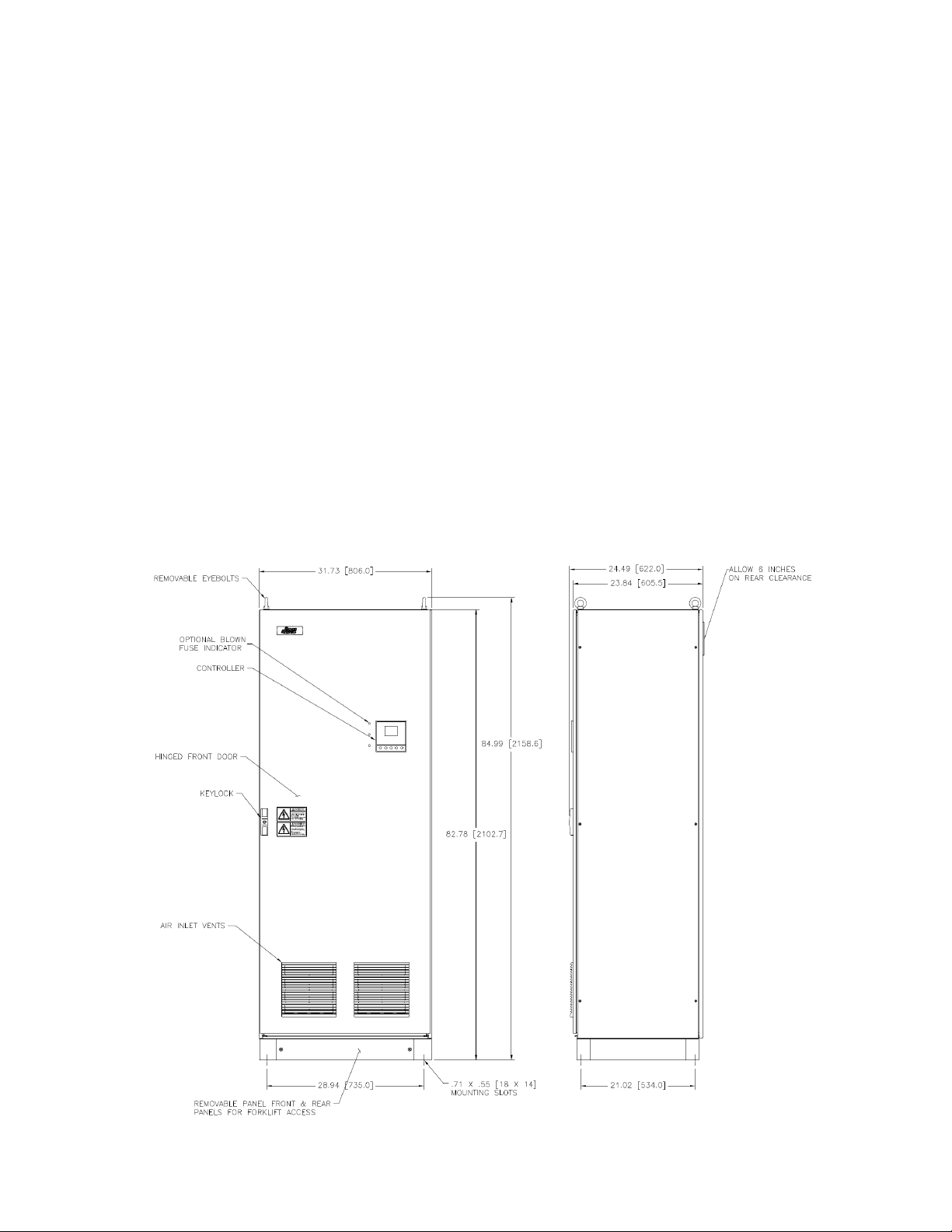
Figure 1 – Standard NEMA 1 Floor Mount Single Enclosure.................................................................... 1
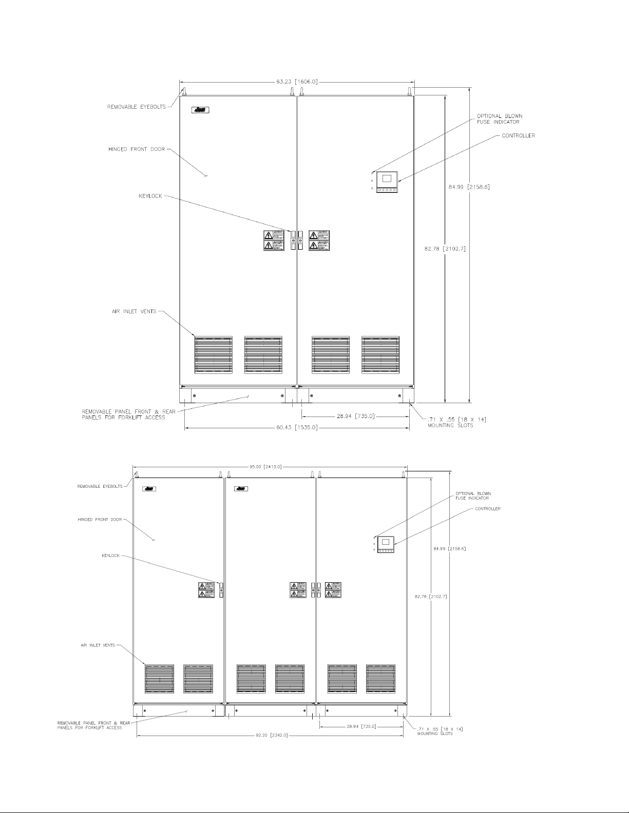
Figure 2 – Standard NEMA 1 Floor Mount Double Enclosure .................................................................. 2
Figure 3 – Standard NEMA 1 Floor Mount Triple Enclosure..................................................................... 2
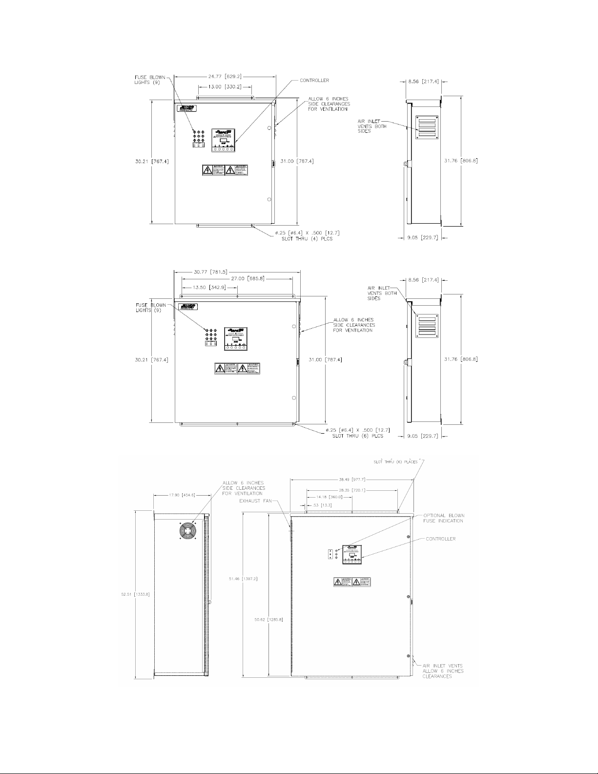
Figure 4 – Standard Wall Mount (Mini) Enclosure .................................................................................... 3
Figure 5 – Large Wall Mount (Mini) Enclosure ......................................................................................... 3
Figure 6 – Standard Floor Mount (Mini) Enclosure ................................................................................... 4
Figure 7 – Recommended CT Placement ................................................................................................ 7
Figure 8 – Typical Control Panel .............................................................................................................. 7
Figure 9 – Controller Diagram.................................................................................................................. 9
Figure 10 – Menu Tree........................................................................................................................... 11
Figure 11 – Alarm Screens .................................................................................................................... 15
Tables
Table 1 – Default Settings...................................................................................................................... 19
Table 2 – Technical Specifications......................................................................................................... 23
Table 3 – Troubleshooting ..................................................................................................................... 25
Page | 1
1. General Description
The StacoVAR system is designed to be used in low voltage (208-600vac), 3-phase, 60 Hz networks;
and is a complete system, which is capable of automatically connecting and disconnecting the capacitor
banks by means of switching devices (electro-mechanical) under the supervision of the Power Quality
Controller (PQC).
The StacoVAR system is designed to control and regulate capacitor banks (steps). This system utilizes
the PQC to continuously calculate the reactive and active power components in the supply network using
the measurement data from the current path (current transformer) and the voltage path (voltage
measurement connection). If the reactive power component exceeds certain thresholds, which the PQC
has determined during the calibration procedure or which have been set as described, switching
commands are given via the instrument outputs. If the inductive reactive power is greater than the value
preset during instrument configuration (target cos φ), after an adjustable time delay one or more of the
PQC control contacts are closed. The PQC thus switches capacitor steps in as required in order to
restore the target power factor. If the inductive reactive power component of the loads reduces again,
this causes capacitor steps to be switched out. The PQC makes a variety of options possible for
customizing the control settings to suit the individual application. The clear overview in the display
provides effective monitoring of power factor correction. So-called ‘cyclic switching’ is a useful feature for
prolonging the service life of the installation, since it ensures that all capacitor steps of the same power
rating are on average switched in equally frequently.
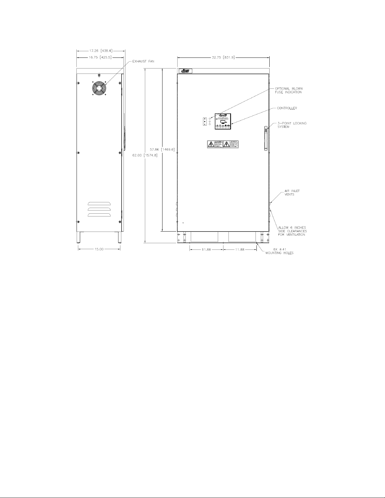
1.1 Layout
Figure 1 – Standard NEMA 1 Floor Mount Single Enclosure
Page | 2
Figure 2 – Standard NEMA 1 Floor Mount Double Enclosure
Figure 3 – Standard NEMA 1 Floor Mount Triple Enclosure
Page | 3
Figure 4 – Standard Wall Mount (Mini) Enclosure
Figure 5 – Large Wall Mount (Mini) Enclosure
Page | 4
Figure 6 – Standard Floor Mount (Mini) Enclosure
1.2 Components
Module Assembly (Enclosure) - Steel modular trays are located inside the enclosure. Each module will
contain components such as power capacitors, switching devices, reactors (PFH models only), fusing
and electrical bus bars. Modules will be installed in a vertical fashion, as required, to accommodate total
kVAR requirements.
Capacitor Bank - Assembly composed of capacitors and their corresponding connection and protection
devices; the bank is managed by one of the output relays of the Automatic Reactive Power Controller.
There are two families of Power Factor Correction Products - Power Factor Correction (only) [PFA] and
Power Factor Correction with harmonic mitigation [PFH].
Capacitors - Individual modules will contain three-phase power capacitors (internally connected in either
delta or wye arrangement), with finger proof terminal protection and equipped with fixed discharge
resistors. Capacitors are rated for the proper kVAR, voltage and frequency, may have individual switched
steps, or be fixed, and when combined, meet the total kVAR requirements.
Step - The number of units into which the total power of the equipment is divided, as governed by the
controller; a single step may be formed by one or more banks.
Reactors (Applications for Harmonics Environments)- To protect capacitors from harmonic currents,
each capacitor bank (in PFH models only) is fitted with a three-phase iron-core reactor detuned to the
3.78th harmonic. A fan package is provided for additional forced air ventilation.

Page | 5
Switching Devices/Fuses/Blown Fuse Indication - The operation of the capacitors is conducted by
means of motor load contactors, which are suitable for the connection of capacitors. Protection against
short-circuits are assured using a set of three NH-00 or NH-000, gRL, 200kaic fuses (one per phase) for
each capacitor step in the PFA and PFH models. The PFM model is protected by RK5, dual element,
time-delayed fuses. Blown fuse indicator are optional.
Disconnection (Optional) – Three-pole molded case type with a thermal-magnetic trip disconnect
switch available upon request. Higher kAIC rating breaker are available with additional request.
Automatic Power Quality Controller - The Power Quality Controller (PQC) continuously calculates the
reactive and active power components in the supply network using the measurement data from the
current path (current transformer) and the voltage path (voltage measurement connection). If the reactive
power component exceeds certain thresholds, which the PQC has determined during the calibration
procedure or which have been set as described, switching commands are given via the instrument
outputs. The PQC makes a variety of options possible for customizing the control settings to suit the
individual application. The clear overview in the display provides effective monitoring of power factor
correction. So-called ‘cyclic switching’ is a useful feature for prolonging the service life of the installation,
since it ensures that all capacitor steps of the same power rating are on average switched in equally
frequently.
2 Safety Instructions
This automatic power factor correction system was manufactured and tested in conformity with current
standards and left the factory in perfect conditions of technical safety.
In order to maintain these conditions and ensure safe operation, the user must abide by the instructions
provided herein.
WARNING
This device must be installed by qualified personnel in accordance with the equipment regulations
currently in force in order to prevent injury or damage to persons or property.
Maintenance or repair work must be managed solely by authorized personnel.
Before undergoing any maintenance or repairs, the device must be disconnected from all power sources.
The constructor disclaims all liability for any injury or damage caused to persons or property as a result
of improper use of its products.
In view of the continuous evolution of our technology, we reserve the right to change the specifications
contained herein without notice. The catalogue descriptions and data shall thus have no contractual
validity.
CAUTION!
The following operations must be performed before accessing the inside of the
equipment:
1. Disconnect the Utility power
2. Wait at least five (5) minutes for discharging capacitors. Confirm by use of a voltmeter for both
AC and DC.
3. Then short circuit and earth all the capacitors.
3. Installation

Page | 6
•Check the Safety Instructions.
•Any incorrect connection or handling may cause damage to the system. Read these instructions
carefully and follow the steps indicated.
•This system must be installed by qualified electrician.
Correct installation is required for proper performance and function of the equipment. Physical inspection
of equipment for damage is recommended, prior to any installation.
•Indoor storage for indoor and outdoor rated equipment should be in a clean, dry environment.
Outdoor storage of outdoor equipment shall require installation of any materials shipped for site
assembly, such as fans and bus ducts and the mating of equipment at shipping splits.
•Equipment includes removable lifting lugs, for transport and site installation handling (except for
the PM models). Placement of the assembly shall be at a level and solid location. The equipment
is designed for floor mounted installations generally with the entrance for the cables from the
bottom or rear (top or side for the PM models).
•Equipment should be placed in a well-ventilated environment and air must be able to circulate
freely. It is important to keep floor mounted models away from walls or other equipment. A gap of
at least 6 inches [15cm] minimum must be maintained at the rear (sides for the PM models) of the
unit to ensure adequate ventilation.
National Electrical Code (NEC), electric utility company, local area or service provider codes shall be
adhered to during the installation. Electrical connections shall also be in compliance with required codes.
Installer/Contractor shall inspect and verify proper alignment, anchorage and grounding, proper
connections, and tightness of connections, prior to any start-up functions.
Appropriate personnel shall start-up and operate equipment upon installation approval.
3.1 Placement of the CT
The StacoVAR must be connected so that it can sample the current of one phase and the voltage
between the other two phases.
The monitored voltage is derived inside the unit between phase L2 and L3 (the central pole and the one
to the right of the main busbars); the CT, therefore, must be inserted in the phase connected to the pole
L1 (the left pole) of the main busbars.
1. The C.T. must have a value:
•at the primary winding: equal to or larger than the maximum current absorbed by the load
downstream from the C.T. itself.
•at the secondary winding: 5A.
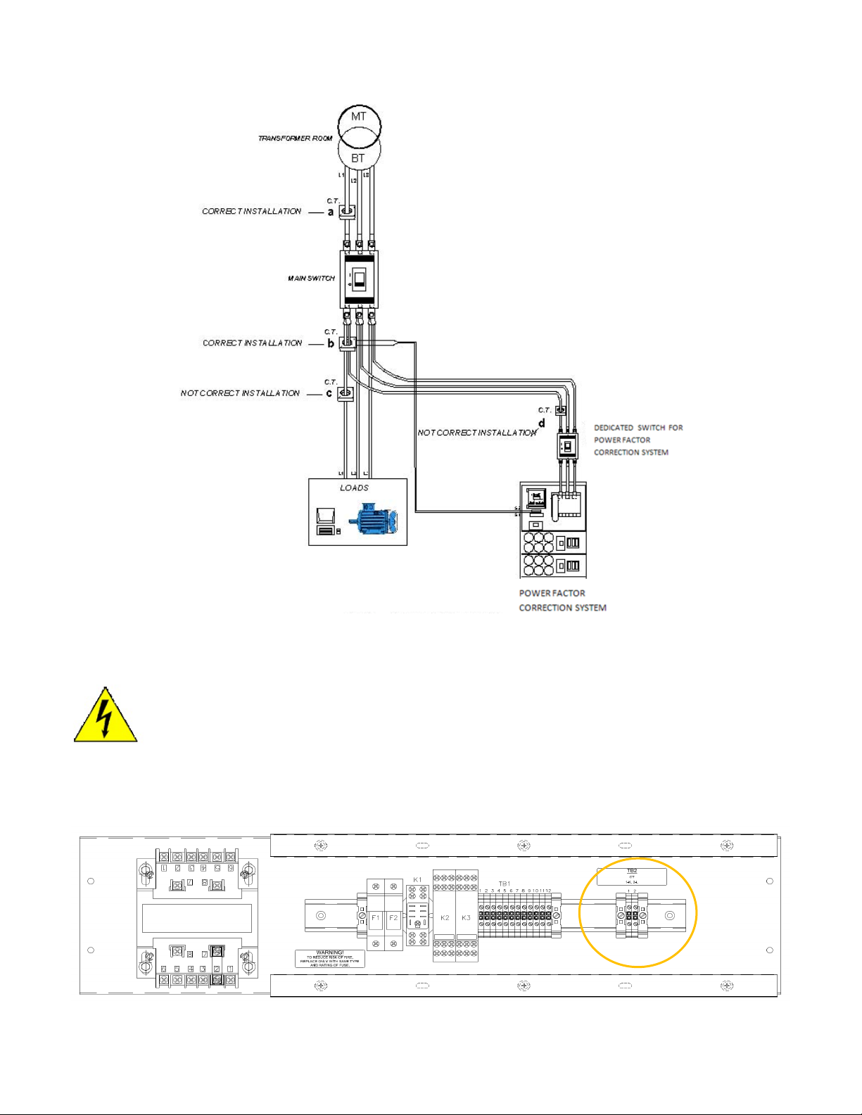
2. The C.T. must be connected both upstream from the power factor correction system and
upstream from the load (See Figure 7positions a and b).
3. The C.T. must never be directly connected on the load power supply line (See Figure 7position
c) or directly on the power factor correction line (See Figure 7position d).
4. The C.T. should not be connected to the phases used for the voltmetric supply (L2 & L3) to the
controller.
Page | 7
Figure 7 – Recommended CT Placement
3.2 CT Connection
When working with CTs, the secondary (terminals on the unit or wires from the unit) must either be
shorted together or properly connected to the intended load (e.g., controller). An open circuit CT
secondary may develop lethal voltage (this precaution is not required if the bus or cable through the
CT is not energized).
The CT wires are connected to TB2 on the control panel. The standard CT is a Multi-Tap split core type
but others may be used upon request. Mark the connections somewhere easy to reference.The logic
of the Power Factor system must have the correct CT ratio to function.
Figure 8 – Typical Control Panel

Page | 8
NOTE: Do not remove factory wiring on the controller
For connection of CT, please reference the system schematic provided with the unit. If the schematic is
not available, contact Staco Energy Products at our toll-free number 1.866.261.1191.
3.3 Connection to Utility
Connect the earth ground lug provided inside the enclosure to the PE earth lead. Rated current values
for protection device should be more than 1.25-1.5 times nominal current.
Connect L1, L2 and L3 terminals of the main lugs or circuit breaker provided inside the enclosure to the
network using 75°C minimum copper leads of the proper gauge.
•If the unit does not have the optional circuit breaker, a disconnect device (switch or circuit
breaker) must be installed between the StacoVAR and the power system per NEC requirements.
4. PQC Operation
4.1 User Interface
The five keys displayed below are used to operate the power quality controller (PQC).
Key
Action PQC Overview Select Select Open Submenu Display Information
NOTE: The keys are each assigned distinct functions according to the current menu active
Escape Go back one level in the system tree.
Up Increase a selected parameter by an increment.
Move a selected item upwards.
Down Decrease a selected parameter by an increment.
Move a selected item downwards.
Return/Enter
Go one level deeper in the system tree
(e.g., Select a chosen parameter).
Select and confirm a chosen parameter
(e.g., Adopt a value).
Info Help Text

Page | 9
4.2 Password Protection
The PQC uses a password to prevent sensitive menu items from being accessed by unauthorized
persons.
•Main menu > Configuration
Security level 1, Password: last four digits of the serial number (see label on PQC or About PQC
menu.
•Main menu > Configuration > Service > Reset Switch. Count
•Main menu > Configuration > Service > Service
Security level 2, Consult Factory for Password.
The user is prompted to enter the password as soon as a protected menu is selected.
The ↑and ↓ keys are used to adjust each digit, which is then confirmed with the key. Once the 4th digit
has been confirmed with this key, the menus at the security level concerned become accessible for one
hour.
4.3 Output Relays (Control outputs)
The PCQ is equipped with 12 output relays wired at the factory. The output relays Q1-Q12 receive their
control voltage from the common feed P.
Figure 9 – Controller Diagram

Page | 10
4.4 Alarm Contact
The StacoVAR power quality controller contains a volt-free contact to transmit alarms externally, alarm
terminals a and b are provided. See Figure 9 – Controller Diagram above for wiring details. Attention
must be paid to the load rating of the alarm contacts (see Section Table 2 – Technical Specifications
for more information).
5. Initial Start-up
Every StacoVAR system is tested and configured at the factory. The connection type, steps (kVAR) and
system voltage will remain the same. The CT parameter will need to be adjusted on start-up.
5.1. Start-Up
Apply utility power to the StacoVAR system. Enter the System Parameter menu by selecting enter in the
main menu. Navigate to Configuration and select System parameters. The CT ratio must be updated to
the ratio of the installed CT. Refer to value recorded in section 3.2 CT Connection.
The CT ratio is calculated as follows
. For example, the factory test CT is 500:5A and the
value programmed in the controller will be 100 from factory testing.
Highlight the CT value and press enter to update the value. Use the ↑ and ↓ arrows to adjust to desired
value. Press enter to save.
5.2 Auto Commissioning
Auto commissioning can be selected at any time to fine-tune the StacoVAR to specific load applications.
It is recommended that the factory settings be kept whenever possible.
All configuration data is saved in a non-volatile memory. In the event of power loss (intended or not)
these data are not lost. When the power supply returns, the PQC starts up automatically and begins the
control process after booting up.
To enter the commissioning menus, enter the main menu and navigate to configuration service. Enter
the password (4-digit serial number on controller label) see 4.2 Password Protection. Select
commissioning. Use the ↓ arrow to highlight Continue. Once pressed the system will start the auto
commissioning process (there is a ~20 second delay before the steps will switch on).
Page | 11
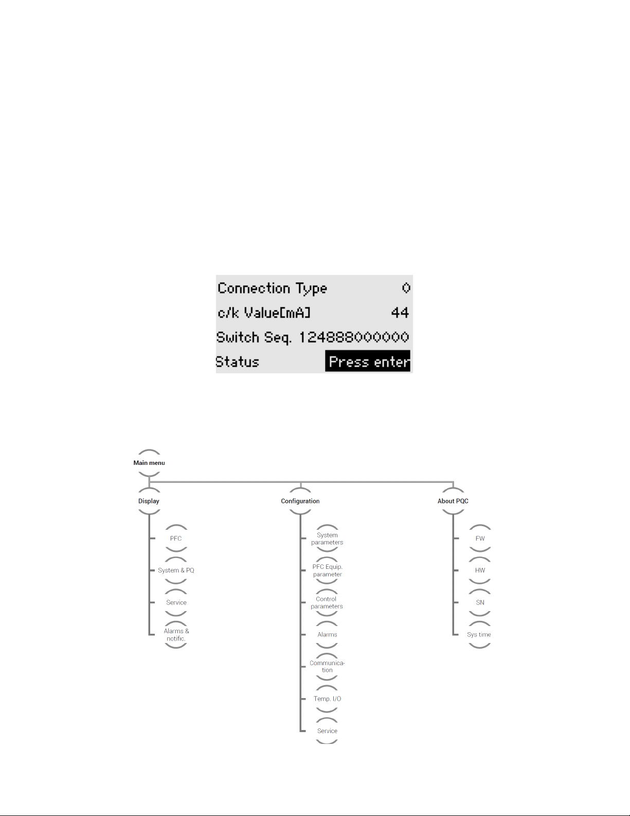
The PQC switches the individual output relays one after the other and identifies not only the phase angle
of the current and voltage measurement paths but also to which output each capacitor stage is assigned.
Each output is switched several times until the PQC can verify the measured values. When identifying
steps automatically, the PQC determines the capacitance value of each switching output relative to that
of the smallest stage. These relative values are displayed as a switching sequence. Relative values > 9
are represented by letters (a = 10, b = 11, ...).
When the PQC has successfully completed the connection and stage identification procedure, the
operator must confirm the result with the key. The PQC then switches to operating mode and displays
the PQC overview screen. If at this moment there is a concrete need for reactive power control, the PQC
commences to switch steps in or out as necessary. If the PQC has not been successful in completing the
connection and stage identification procedure, the notifications ‘Connect detection failed’ or ‘Stage
detection failed’ are displayed.
If the ESC key is pressed to cancel the automatic connection and stage identification procedure, the
notification ‘Terminate identification’ is displayed.
6. Display Operation
All measurements and settings can be displayed from the main menu of the StacoVAR power quality
controller. The main menu is comprised of three main groups: Display, Configuration, and About PQC.
Figure 10 – Menu Tree
Page | 12
6.1 Display Menus
All readings and parameters relevant to the power factor correction are shown. The main Display menu
items are:
PFC Measurement readings relevant to power factor correction
System and PQ Network and power quality parameters
Service Status display
Alarms & Notifications Display of momentary alarms and the alarm history
6.1.1 PFC menu
This menu contains three submenus: Overview, Utilization, and Switching Outputs.
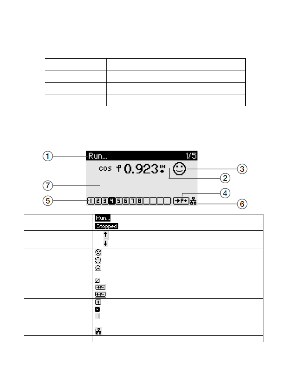
1. Main menu > Display > PFC > Overview
The Overview screen makes it possible to view all the information relevant to power factor
correction. Use the Return key to browse through the following displays.
1. Control Status
= System Running
= Fault in System
2. Steps engaging or
disengaging = Switching capacitive power in
= Switching capacitive power out
3. PQC Explorer
= System within control band OK
= System outside control band, PQC trying to optimize
= System outside control band, no more capacitive power available -
> WARNING
= Low Load condition
4. Power Symbol
= Power drawn from supply
= Power feed-in to supply
5. Switched Capacitor
steps = Stage available not energized
= Stage energized
= Stage not available
E = Error
6. Communication
7. Alarm Message
If present

Page | 13
2. Main menu > Display > PFC > Utilization
Utilization - The ratio of the momentary switched-in capacitance to the total available
capacitance, expressed as a percentage.
Overcurrent -This parameter is the ratio Irms / I50Hz,60Hz i.e., the theoretically determined ratio
of the momentary RMS current to the fundamental current in the capacitor. The tuning factor p of
the power factor correction system is also considered in this calculation.
Total power (Q) -This parameter is the sum of all the connected 3-phase capacitor stage
corrective powers.
Available power (Q) - This parameter is the 3-phase capacitor corrective power still available for
switching in.
3. Main menu > Display > PFC > Switching outputs
The overview display shows the momentary statuses of all the capacitor steps.
Steps 1, 4, 5, 7, 10, 11: switched-out active steps
Steps 8 and 12: switched-in active steps
A permanently switched-in fixed capacitor stage is shown as a switched-in active stage with an F.
6.1.2 System & PQ
This menu contains six submenus: System, THD, VI harmonics, V-Harm spectrum, I-Harm spectrum,
and Freq. Analysis
1. Main menu > Display > System & PQ > System data
cos φ - Display of the momentary power factor cos φ
VΔ /V VΔ -phase-phase voltage / V phase-neutral voltage
P - Display of the momentary active power
Q - Display of the momentary reactive power (if capacitive reactive power with a minus sign)
I- Display of the momentary current
S- Display of the momentary apparent power
Σ- Theoretical calculation of the sum assuming a balanced load

Page | 14
2. Main menu > Display > System & PQ > THD
Display of THDv and THDi and their magnitudes as percentages of the fundamental H1 Single phase
PQC: display of Lx and Ix
3. Main menu > Display > System & PQ > V/I harmonics
Display of percentage values of the voltage and current harmonics together with the fundamental
values for voltage and current.
4. Main menu > Display > System & PQ > V-harm. spectrum, I-harm. Spectrum
Graphical display of the harmonic’s spectrum up to the 19th
Key
Action Back to
Display menu Zoom + Zoom -
Toggle
between
H1–12 and
H13–19
Additional
info
The fundamental at 50/60 Hz is shown as 100%. One scale division on the y-axis represents 5%.
5. Main menu > Display > System & PQ > I-harm. Spectrum
See number 5 above
6. Main menu > Display > System & PQ > Frequency analysis
Phase - Measurement on L1
Frequency - 10 Hz to 2,500 Hz in steps of 10 Hz
V(f) - Magnitude of voltage at the selected frequency as a
percentage of the fundamental voltage V(f) (f = 50/60 Hz)
I(f) - Magnitude of current at the selected frequency as a percentage of the fundamental I(f)
(f= 50/60 Hz)
Angle φ - Angle between V(f) and I(f) in degrees
Angle γ - Angle between V (fundamental) and I(f) in degrees
Key
Action Info Status
Frequency
+10 Hz
Frequency
-10 Hz
Select
phase
-
Table of contents


