Haslinger HMR 750 User manual
www.hmr-jacob.de
HMR750
D
EN
F
PL
Montageanleitung · Zugstabsystem Seite 2 – 5
Assembly Instructions · Rod Systems page 6 – 9
Instructions de montage · Système de haubanage page 10 – 13
Instrukcja montażu · System cięgnowy bok 14 – 17

1. Montage Zugstabsystem
2
Die HMR Zugstäbe werden in der automatisierten Produktion prozesssicher mit einem Data-Matrix-Code
gekennzeichnet. Aus dieser Kennzeichnung sind alle wesentlichen Auftragsdaten, wie u.a. Stablänge,
Gewindelänge oder auch Werkszeugnisdaten und Positionsnummern über unsere HMR-App auslesbar.
Werkseitige Vormontage
M12 – M36
●Zugstäbe in den Systemgrößen M12 – M36 werden in
transportfähigen Längen vormontiert geliefert.
●Gabelköpfe werden bis zur Mindesteinschraubtiefe auf die
Rundstäbe vormontiert.
●Bolzen werden in separaten Verpackungseinheiten geliefert.
M42 – M100
●Gabelköpfe, Bolzen, Rundstäbe und alle weiteren System-
komponenten werden in separaten Verpackungseinheiten
geliefert.
●Eine Farbcodierung erleichtert die Erkennung der
Gewinderichtung:
➜Grüner Punkt auf Stirnseite Zugstab und Verpackung der
Anschlussteile = Rechtsgewinde
➜Roter Punkt auf Stirnseite Zugstab und Verpackung der
Anschlussteile = Linksgewinde
DMC, Positionsnummer und Schlüsselfläche
Um die Zugstabsysteme auf der Baustelle leichter zuordnen zu
können, sind jeweils ein Data-Matrix-Code und die Positions-
nummer aufgelasert.
Diese Angaben sind auf der Stabseite des Rechtsgewindes
600-800 mm vom Stabende entfernt zu finden.
Sofern eine Schlüsselfläche mitbestellt worden ist, befindet
sich diese auf der gegenüberliegenden Seite bei 580 mm
vom Stabende.
Vormontage und Einbau der Systeme
●Vor Montage sind alle Bauteile auf einwandfreie Beschaffen-
heit zu überprüfen.
●Abdeckhülsen auf den Zugstab aufschrauben.
●Gabelstück mit Rechts- bzw. Linksgewinde symmetrisch
bis mindestens auf die Mindesteinschraubtiefe aufschrauben
(s. 2.).
●Zugstab einschwenken und montieren.
●Den Stab über die Schlüsselfläche spannen, bis die ge-
wünschte Systemlänge erreicht ist.
●Bolzen durch das Gabelloch und das Anschlussblech stecken,
ohne Zuhilfenahme eines Hammers o.ä.
Variante 1 (Standardausführung mit Sicherungsring):
Den Bolzen mit Sicherungsringe mit Hilfe einer Sicherungs-
zange sichern.
Variante 2 (Sonderausführung mit Scheibe):
Die Scheiben mit Senkschrauben befestigen und mit einem
Inbusschlüssel anziehen.
●Das System durch Drehen des Stabes spannen.
Alternative 1:
Sind Schlüsselflächen am System vorhanden, kann das
System über Drehen mit dem Maulschlüssel an den
Schlüsselflächen gespannt werden.
Alternative 2:
Sind keine Schlüsselflächen vorhanden, empfehlen wir den
Gebrauch von Gurt- oder Kettenschlüsseln. Bei korrosions-
geschützten Zugstäben können durch die Spannarbeiten,
Schäden an der Oberfläche der Schlüsselfläche bzw. des
Stabes entstehen. Derartige Fehlstellen müssen bauseits
fachgerecht nachgebessert werden.
Alternative 3:
Das Zugstabsystem lässt sich außerdem mit dem HMR-
Vorspanngerät planmäßig vorspannen. Die Vorspannvor-
richtung kann von HMR Jacob gekauft oder geliehen
werden.
●Nach Spannen des Zugstabes, Abdeckhülsen bis zum
Gabelkopf vordrehen und mit einem Gelenk-Hakenschlüssel
kontern.
Montageanleitung HMR 750 Zugstabsystem
D
Stablänge
580
Gewinde Seite 2
Rechts / Links
Gewinde Seite 1
Rechts
Schlüsselfläche DMC
max. 25 600-800
max. 500max. 500

3
Montageanleitung HMR 750 Zugstabsystem D
Zugstab mit SpannschlossZugstab mit Gabelköpfen
●Abdeckhülsen auf den Zugstab aufschrauben.
●Gabelstück mit Rechts- bzw. Linksgewinde und Spannschloss
bis mindestens auf die Mindesteinschraubtiefe aufschrauben.
●Zugstab einschwenken und montieren.
●Spannschloss festhalten und beide Stäbe über die Schlüssel-
fläche symmetrisch spannen.
Achtung: Die Mindesteinschraubtiefe muss an den Gabel-
köpfen und beim Spannschloss immer gewährleistet sein!
●Nach Spannen des Zugstabes, Abdeckhülsen bis zum Gabel-
kopf und Spannschloss vordrehen und mit einem Gelenk-
Hakenschlüssel kontern.
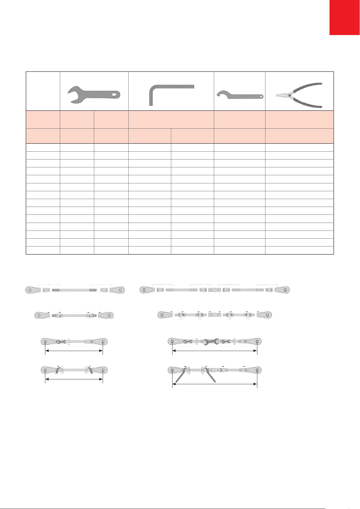
Montagewerkzeuge
Gewinde-Ø für für für Senkschraube für Senkschraube für für
Zugstab Spannschloss DIN EN ISO 10642 DIN EN ISO 10642 Abdeckhülse Sicherungsringe
M SW SW Größe SW Größter Ø / Ø Sicherungsring
mm mm mm Zapfen Ø mm mm
12 10 18 M4 x 10 2,5 35/3 12-25
16 13 23 M5 x 10 3 35/3 12-25
20 16 28 M6 x 16 4 35/3 12-25
24 20 32 M6 x 16 4 35/3 12-25 / 19-60
30 25 41 M6 x 16 4 60/4 19-60
36 30 50 M6 x 16 4 60/4 19-60
42 36 60 M8 x 20 5 60/4 19-60 / 40-100
48 42 70 M10 x 25 6 90/5 19-60 / 40-100
56 49 80 M10 x 25 6 90/5 19-60 / 40-100
64 56 92 M10 x 25 6 155/6 40-100
76 68 112 M10 x 25 6 155/6 40-100
85 78 125 M10 x 25 6 155/6 40-100 / 85-140
90 82 135 M10 x 25 6 155/6 40-100 / 85-140
100 91 150 M10 x 25 6 155/6 85-140
Maulschlüssel Inbusschlüssel Gelenk-Hakenschlüssel Sicherungsringzange
Linksgewinde Linksgewinde LinksgewindeRechtsgewinde Rechtsgewinde Rechtsgewinde
Spannschloss gegenhalten / spannen über Schlüsselfläche an den Zugstäben
Systemlänge L
Systemlänge L Systemlänge L
Systemlänge L
kontern kontern
spannen
Abdeckhülsen aufdrehen
Gabelstücke aufschrauben
Abdeckhülsen aufdrehen
Gabelstücke und Spannschloss aufschrauben

4
2. Bestimmung der Mindesteinschraubtiefe
4. Anordnung der Anschlussbleche
3. Korrosionsschutz des Systems
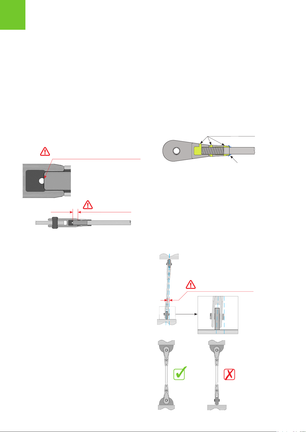
●Alle Gabelköpfe, Spannschlösser und Kreuzmuffen sind mit
einer Kontrollbohrung ausgeführt, die zur Kontrolle der
Mindesteinschraubtiefe dient.
●Ist das Gewinde des Stabes in der Kontrollöffnung zu sehen,
so ist die Mindesteinschraubtiefe erreicht.
●Muffen sind bis zum Anschlag aufzuschrauben. Damit ist
bei diesem Bauteil die Mindesteinschraubtiefe erreicht.
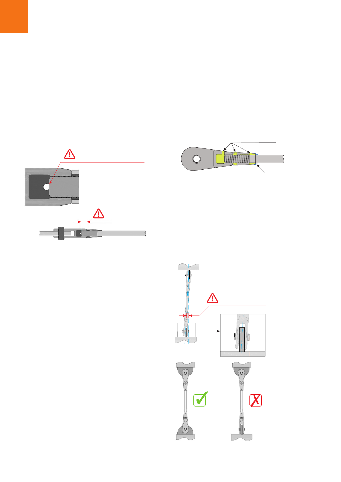
Beispiel Gabelkopf:
Bei der Montage ist zu beachten, dass die maximale Ab-
weichung der Systemachse 0,5° nicht überschreitet und
gegenüberliegende Anschlussbleche in einer Ebene angeordnet
sind. Hierdurch werden unerlaubte Biegemomente vermieden.
Vorgehensweise Injektionsarbeiten:
●Anforderungen der Taupunkttemperatur beachten,
s. Datenblatt Taupunkttemperatur HMR Dichtmittel.
●Alle Gewindeteile von Verunreinigungen befreien.
●Das offene Ende der Abdeckhülse mit einem Klebeband
umwickeln.
●Dichtmittel injizieren.
●Klebeband unmittelbar nach Abschluss der Injektionsarbeiten
entfernen.
Achtung! Ein Nachspannen der Zugstäbe ist nach Abdichten
der Gewinde nicht mehr möglich!
Das Endgewinde des Zugstabes erreicht die Korrosivitätskate-
gorie C3 mit langer Schutzdauer und gewährleistet damit den
gleichen Korrosionsschutz, wie die feuerverzinkte Oberfläche
des Stabes.
Um allerdings durch Eindringen von Wasser in den Gewinde-
bereich eine Spaltkorrosion zu verhindern, empfehlen wir die
Verwendung des dauerelastischen HMR-Dichtmittels.
Voraussetzungen:
Zum Abdichten des Gewindebereichs ist bei Zugstäben mit
Gabelköpfen immer eine Abdeckhülse einzusetzen. Die Ab-
deckhülse wird komplett bündig zum Schaft des Gabelkopfes
aufgedreht. Die Abdeckhülse hat 4 Bohrungen, in die jeweils
Dichtmittel injiziert werden kann.
Im Anschluss ist auch das Kontrollloch des Gabelkopfes
abzudichten.
Die gleiche Vorgehensweise wird auch beim der
Kreuzmuffe oder des Spannschlosses empfohlen. Auch hier
kann das Dichtmittel über die Bohrungen injiziert werden,
um den Gewindebereich zu verschließen.
Gabelkopf mit dauerelastischer Verfüllung der Hohlräume.
Injektionsöffnungen
Klebeband
Montageanleitung HMR 750 Zugstabsystem
D
Maximale Abweichung
von der Soll-Ausrichtung: 0,5°
Wenn Stab im Kontrollloch sichtbar ist,
ist die Mindesteinschraubtiefe erreicht
Mindesteinschraubtiefe

5
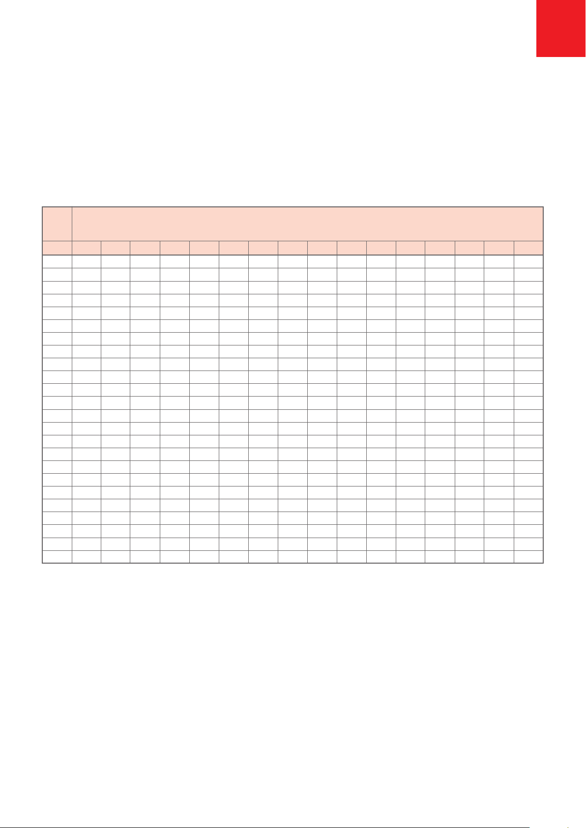
Taupunkttemperatur des HMR-Dichtmittels
Lufttemp Taupunkttemperatur in °C bei einer relativen Luftfeuchtigkeit von
in °C 20% 25% 30% 35% 40% 45% 50% 55% 60% 65% 70% 75% 80% 85% 90% 95%
+2 * * * * * * * * * * * * * * +0,5 +1,3
+4 * * * * * * * * * * * +0,0 +0,9 +1,7 +2,5 +3,3
+6 * * * * * * * * * * +1,0 +1,9 +2,8 +3,7 +4,5 +5,3
+8 * * * * * * * * +0,7 +1,9 +2,9 +3,9 +4,8 +5,6 +6,5 +7,3
+10 * * -6,0 -4,2 -2,6 -1,2 +0,1 +1,4 +2,6 +3,7 +4,8 +5,8 +6,7 +7,6 +8,4 +9,2
+12 * * -4,5 -2,6 -1,0 +0,4 +1,9 +3,2 +4,5 +5,7 +6,7 +7,7 +8,7 +9,6 +10,4 +11,2
+14 * * -2,9 -1,0 +0,6 +2,3 +3,7 +5,1 +6,4 +7,5 +8,6 +9,6 +10,6 +11,5 +12,4 +13,2
+15 * * -2,2 -0,3 +1,5 +3,2 +4,7 +6,1 +7,3 +8,5 +9,6 +10,6 +11,6 +12,5 +13,4 +14,2
+16 * * -1,4 +0,5 +2,4 +4,1 +5,6 +7,0 +8,2 +9,4 +10,5 +11,6 +12,6 +13,5 +14,4 +15,2
+17 * * -0,6 +1,4 +3,3 +5,0 +6,5 +7,9 +9,2 +10,4 +11,5 +12,5 +13,5 +14,5 +15,3 +16,2
+18 * * +0,2 +2,3 +4,2 +5,9 +7,4 +8,8 +10,1 +11,3 +12,5 +13,5 +14,5 +15,4 +16,3 +17,2
+19 * * +1,1 +3,2 +5,1 +6,8 +8,3 +9,8 +11,1 +12,3 +13,4 +14,5 +15,5 +16,4 +17,3 +18,2
+20 * * +1,9 +4,1 +6,0 +7,7 +9,3 +10,7 +12,0 +13,2 +14,4 +15,4 +16,4 +17,4 +18,3 +19,2
+21 * +0,3 +2,8 +5,0 +6,9 +8,6 +10,2 +11,6 +12,9 +14,2 +15,3 +16,4 +17,4 +18,4 +19,3 +20,2
+22 * +1,1 +3,7 +5,9 +7,8 +9,5 +11,1 +12,5 +13,9 +15,1 +16,3 +17,4 +18,4 +19,4 +20,3 +21,2
+23 * +1,9 +4,5 +6,7 +8,7 +10,4 +12,0 +13,5 +14,8 +16,1 +17,2 +18,3 +19,4 +20,3 +21,3 +22,2
+24 * +2,8 +5,4 +7,6 +9,6 +11,3 +12,9 +14,4 +15,8 +17,0 +18,2 +19,3 +20,3 +21,3 +22,3 +23,1
+25 +0,5 +3,6 +6,2 +8,5 +10,5 +12,2 +13,9 +15,3 +16,7 +18,0 +19,1 +20,3 +21,3 +22,3 +23,2 +24,1
+26 +1,3 +4,5 +7,1 +9,4 +11,4 +13,2 +14,8 +16,3 +17,6 +18,9 +20,1 +21,2 +22,3 +23,3 +24,2 +25,1
+28 +3,0 +6,1 +8,8 +11,1 +13,1 +15,0 +16,6 +18,1 +19,5 +20,8 +22,0 +23,2 +24,2 +25,2 +26,2 +27,1
+30 +4,6 +7,8 +10,5 +12,9 +14,9 +16,8 +18,4 +20,0 +21,4 +22,7 +23,9 +25,1 +26,2 +27,2 +28,2 +29,1
+32 +6,2 +9,5 +12,2 +14,6 +16,7 +18,6 +20,3 +21,8 +23,3 +24,6 +25,8 +27,0 +28,1 +29,2 +30,2 +31,1
+35 +8,7 +12,0 +14,8 +17,2 +19,4 +21,3 +23,0 +24,6 +26,1 +27,4 +28,7 +29,9 +31,0 +32,1 +33,1 +34,1
+40 +12,8 +16,2 +19,1 +21,6 +23,8 +25,8 +27,6 +29,2 +30,7 +32,1 +33,5 +34,7 +35,9 +37,0 +38,0 +39,0
* keine Kondensatbildung möglich
Die Taupunkttabelle gibt an, bei welchen Oberflächentempe-
raturen Kondensat auftritt – in Abhängigkeit von der Lufttem-
peratur und der relativen Luftfeuchtigkeit. Beispiel: Bei 20°C
Luft- temperatur und 70% relativer Luftfeuchtigkeit liegt der
Taupunkt bei einer Objekttemperatur von +14,4°C.
Zeigt das Oberflächenthermometer einen Wert kleiner als
+ 17,4°C (14,4°C + 3°C Sicher- heitsfaktor) an, sollten
keine Verklebungsarbeiten mehr ausgeführt werden.
Das Oberflächenthermometer kann bei HMR Jacob geliehen
oder gekauft werden.
Montageanleitung HMR 750 Zugstabsystem D

HMR 750 Assembly Instructions
EN
6
1. Tendon Assembly
HMR 750 Tension Rods are manufactured with high process reliability on an automated production line.
Each Tendon is labelled with a Data Matrix code which contains information such as rod length, thread lengths,
rod marking and certification data. The information can be obtained by using the HMR app.
Factory pre-assembly M12 (1/2”) - M36 (1-3/8”)
●All tendons up to M36 (1-3/8”) are delivered
pre-assembled in bundles.
●Tendons longer than 12m (39’4”) are split into
transportable lengths and will be pre-assembled up to
a coupler or a turnbuckle.
●Tension Rods are set to the minimum thread engagement.
●Pins are packed separately in boxes.
M42 (1-5/8“) – M100 (4“)
●Rods and fittings will be packed separately and site assembly
will be required.
All rods are color coded which allows easy identification
of thread directions.
●Green marking placed on the front face of the rod and
on packaging of fittings = RH thread
●Red marking placed on the front face of the rod and
on packaging of fittings = LH thread
DMC, bar mark and spanner flat
Every Tension Rod is marked with a Data Matrix Code and
bar mark for easy identification on site. These are located
at 600-800 mm on the RH thread.
If a spanner flat has been ordered, it can be found on the
opposite side at 580 mm from the end of the rod.
On-site tension rod assembly and installation
●Prior to installation please check that all components are
present and no damage has occurred.
●Assemble the lock covers on to the rod
●Assemble forks symmetrically and turn fork connectors
equally until pin to pin length is set
●Swing the rod into place.
●Insert the pins through the fork heads and gusset plates
(do not use any force i.e. a hammer)
– Standard pin option: Pin with circlip
●Secure the circlips on the pins by using a circlip plier
– Pin option 2: Pin with washer
●Secure the washers on to the pins by fastening the
countersunk screw with an allen key.
●Tension and adjust the rod.
Tension Rod with spanner flat:
Place a spanner on the spanner flat and induce the
load/adjustment required.
Tension Rod with no spanner flat:
For rods with no spanner flat, we recommend the use of
a strap wrench.
Hydraulic Stressing:
Where large loads need to be induced the HMR pretension
unit can be used. The equipment can be hired or bought
from HMR Jacob.
●Screw lock covers back against the forks, couplers,
turnbuckles and cross couplers using a hook spanner with pin.
Note:
Galvanized or painted Tendons may be damaged by transport,
handling and site installation. Any surface damage must be
repaired.
Tension Rod Length
580
Thread End 2
RH/LH
Thread End 1
RH
Spanner Flat DMC
max. 25 600-800
max. 500max. 500

HMR 750 Assembly Instructions EN
7
Assembly of Tension Rod with TurnbuckleTension Rod with Fork
●Assemble the lock covers on to the rod
●Assemble forks and turnbuckle until the pin to pin length
is set and note minimum thread engagement as shown
in section 2.
●Swing the rod into place.
●Insert the pins through the fork heads and gusset plates
(do not use any force i.e. a hammer)
●Hold turnbuckle in place. Adjust and torque the load
symmetrically via the spanner flats on the rods. Thread
engagement on forks and turnbuckle must always be ensured!
●Screw lock covers back against the forks and turnbuckle
using a hook spanner with pin.
LH Thread LH Thread LH ThreadRH Thread RH Thread RH Thread
Hold Turnbuckle in place / Adjust and Induce Load via the spanner flats
Pin to Pin Length
Pin to Pin Length Pin to Pin Length
Pin to Pin Length
Tighten Lock Cover Tighten Lock Cover
Adjust and Induce Load
Assemble Lock Covers
Adjust and Induce Load
Assemble Lock Covers
Assemble Forks and Turnbuckle
Assembly Tools
Thread-Ø Rod Turnbuckle Pin with washer countersunk screw Lock Cover for Circlips
DIN EN ISO 10642
M AF AF Size AF Biggest Ø / Pin Ø Circlip Ø
mm mm mm
12 10 18 M4 x 10 2,5 35/3 12-25
16 13 23 M5 x 10 3 35/3 12-25
20 16 28 M6 x 16 4 35/3 12-25
24 20 32 M6 x 16 4 35/3 12-25 / 19-60
30 25 41 M6 x 16 4 60/4 19-60
36 30 50 M6 x 16 4 60/4 19-60
42 36 60 M8 x 20 5 60/4 19-60 / 40-100
48 42 70 M10 x 25 6 90/5 19-60 / 40-100
56 49 80 M10 x 25 6 90/5 19-60 / 40-100
64 56 92 M10 x 25 6 155/6 40-100
76 68 112 M10 x 25 6 155/6 40-100
85 78 125 M10 x 25 6 155/6 40-100 / 85-140
90 82 135 M10 x 25 6 155/6 40-100 / 85-140
100 91 150 M10 x 25 6 155/6 85-140
Spanner Allen Key Hook Spanner with pin Circlip Plier
HMR 750 Assembly Instructions
EN
8
2. Minimum thread engagement
4. Gusset Plate Misalignment
3. Corrosion Protection
●All forks, turnbuckles and cross couplers are supplied with
an inspection hole allowing easy control of minimum
thread engagement.
●Thread is sufficiently engaged when the rod is visible
in the opening of the fork, turnbuckle or cross coupler.
●Couplers are fitted with a thread stop to determine
thread engagement.
Fork Example :
When installing the Tension Rod System ensure that the
maximum misalignment does not exceed 0,5°. Forks should
be kept in plane to each other as shown below. This prevents
bending on the forks and gusset plates.
Prior to sealant application:
●Check dow temperatures as per dow temperature datasheet.
●Remove any dirt and dust.
●Tape off the gap between the opening of the lock cover
and rod.
●Remove tape after sealant is applied.
No more tensioning or adjusting can be done after
threads are sealed!
The HMR Jacol corrosion protection on rod threads guarantees
480 hours corrosion resistance in salt spray exposure and
offers durability compliant to corrosivity category C3 high,
therefore ensuring the same corrosion protection as the
galvanized rod.
In order to avoid crevice corrosion which could occur if there
is water retention in an unsealed thread, we recommend
the use of the HMR sealant for any exterior applications.
In order to seal the thread area all tendons fitted with a fork
and turnbuckle or cross coupler must be supplied with a
lock cover. The sealant is then to be applied via the
injection/inspection holes.
Sealed off fork end connection.
Injection Hole
Tape
Max. Misalignment: 0,5°
Thread is engaged when thread
is visible in inspection hole
Thread Engagement

HMR 750 Assembly Instructions EN
9
Dew Point Temperature
Air temp. Dow temperatures in °C and relative humidity levels
in °C 20% 25% 30% 35% 40% 45% 50% 55% 60% 65% 70% 75% 80% 85% 90% 95%
+2 * * * * * * * * * * * * * * +0,5 +1,3
+4 * * * * * * * * * * * +0,0 +0,9 +1,7 +2,5 +3,3
+6 * * * * * * * * * * +1,0 +1,9 +2,8 +3,7 +4,5 +5,3
+8 * * * * * * * * +0,7 +1,9 +2,9 +3,9 +4,8 +5,6 +6,5 +7,3
+10 * * -6,0 -4,2 -2,6 -1,2 +0,1 +1,4 +2,6 +3,7 +4,8 +5,8 +6,7 +7,6 +8,4 +9,2
+12 * * -4,5 -2,6 -1,0 +0,4 +1,9 +3,2 +4,5 +5,7 +6,7 +7,7 +8,7 +9,6 +10,4 +11,2
+14 * * -2,9 -1,0 +0,6 +2,3 +3,7 +5,1 +6,4 +7,5 +8,6 +9,6 +10,6 +11,5 +12,4 +13,2
+15 * * -2,2 -0,3 +1,5 +3,2 +4,7 +6,1 +7,3 +8,5 +9,6 +10,6 +11,6 +12,5 +13,4 +14,2
+16 * * -1,4 +0,5 +2,4 +4,1 +5,6 +7,0 +8,2 +9,4 +10,5 +11,6 +12,6 +13,5 +14,4 +15,2
+17 * * -0,6 +1,4 +3,3 +5,0 +6,5 +7,9 +9,2 +10,4 +11,5 +12,5 +13,5 +14,5 +15,3 +16,2
+18 * * +0,2 +2,3 +4,2 +5,9 +7,4 +8,8 +10,1 +11,3 +12,5 +13,5 +14,5 +15,4 +16,3 +17,2
+19 * * +1,1 +3,2 +5,1 +6,8 +8,3 +9,8 +11,1 +12,3 +13,4 +14,5 +15,5 +16,4 +17,3 +18,2
+20 * * +1,9 +4,1 +6,0 +7,7 +9,3 +10,7 +12,0 +13,2 +14,4 +15,4 +16,4 +17,4 +18,3 +19,2
+21 * +0,3 +2,8 +5,0 +6,9 +8,6 +10,2 +11,6 +12,9 +14,2 +15,3 +16,4 +17,4 +18,4 +19,3 +20,2
+22 * +1,1 +3,7 +5,9 +7,8 +9,5 +11,1 +12,5 +13,9 +15,1 +16,3 +17,4 +18,4 +19,4 +20,3 +21,2
+23 * +1,9 +4,5 +6,7 +8,7 +10,4 +12,0 +13,5 +14,8 +16,1 +17,2 +18,3 +19,4 +20,3 +21,3 +22,2
+24 * +2,8 +5,4 +7,6 +9,6 +11,3 +12,9 +14,4 +15,8 +17,0 +18,2 +19,3 +20,3 +21,3 +22,3 +23,1
+25 +0,5 +3,6 +6,2 +8,5 +10,5 +12,2 +13,9 +15,3 +16,7 +18,0 +19,1 +20,3 +21,3 +22,3 +23,2 +24,1
+26 +1,3 +4,5 +7,1 +9,4 +11,4 +13,2 +14,8 +16,3 +17,6 +18,9 +20,1 +21,2 +22,3 +23,3 +24,2 +25,1
+28 +3,0 +6,1 +8,8 +11,1 +13,1 +15,0 +16,6 +18,1 +19,5 +20,8 +22,0 +23,2 +24,2 +25,2 +26,2 +27,1
+30 +4,6 +7,8 +10,5 +12,9 +14,9 +16,8 +18,4 +20,0 +21,4 +22,7 +23,9 +25,1 +26,2 +27,2 +28,2 +29,1
+32 +6,2 +9,5 +12,2 +14,6 +16,7 +18,6 +20,3 +21,8 +23,3 +24,6 +25,8 +27,0 +28,1 +29,2 +30,2 +31,1
+35 +8,7 +12,0 +14,8 +17,2 +19,4 +21,3 +23,0 +24,6 +26,1 +27,4 +28,7 +29,9 +31,0 +32,1 +33,1 +34,1
+40 +12,8 +16,2 +19,1 +21,6 +23,8 +25,8 +27,6 +29,2 +30,7 +32,1 +33,5 +34,7 +35,9 +37,0 +38,0 +39,0
* no formation of condensation
This table shows at which surface temperature condensation
occurs – depending on air temperature and relative humidity.
For example: If air temperature is 20°C/68°F and relative
humidity is 70%, the dew point is at 14.4°C°/57.9°F.
No sealant should be applied if the surface temperature
thermometer shows a value lower than +17,40°C/+63,3 °F
(14,4°C + 3°C safety factor / 57.9°F + 37,4°F safety factor).
The surface temperature thermometer is available to rent
or to buy from JACOB.

1. Montage du tirant
10
Les systèmes de haubanage HMR 750 sont fabriqués selon un processus de production très rigoureux,
sur une ligne de production automatisée.
Chaque tirant est étiqueté avec un code Datamatrix qui contient des informations telles que la longueur du tirant,
les longueurs des filetages, les marquages des tirants ainsi que les données de certification. Les informations
peuvent être obtenues à l’aide de l’application HMR.
Prémontage en usine de la gamme des filetages
M12 (1/2”) – M36 (1-3/8”)
●Tous les tirants supérieur à la dimension M36 (1 -3/8”)
sont fournis prémontés en paquets.
●Les tirants d’une longueur supérieure à 12 m (39’4”)
sont répartis en longueurs transportables, et seront
prémontés à l’aide d’un manchon de raccordement ou
d’un tendeur.
●Les tirants seront montés en respectant le recouvrement
minimal des filetages.
●Les axes sont emballés séparément dans des paquets.
M42 – M100
●Les tirants et les pièces de raccordement sont emballés
séparément et le montage aura lieu sur site.
●Tous les tirants portent un marquage en couleur, ce qui
permet d’identifier facilement le sens du pas des filetages.
➜Le marquage en vert est placé sur la face avant du tirant
et sur l’emballage des pièces de raccordement:
filetage à droite
➜Le marquage en rouge est placé sur la face avant du tirant
et sur l’emballage des pièces de raccordement =
filetage à gauche
CDM, noméro d’item et le méplat
Afin de pouvoir ordonner plus facilement les systèmes
d’haubanage sur le chantier, un code datamatix et le numéro
d’item sont gravés au laser sur chacun des tirants.
Ces données se trouvent du côté du filetage pas à droite,
à 600-800 mm de l’extrémité du tirant.
Si commandé, sur le côté opposé, à 580 mm de l’extrémité
du tirant, se trouve le méplat.
Montage et installation des tirants sur site
●Avant de commencer l‘installation, vérifiez que tous
les composants sont présents et qu’aucune pièce n’a été
endommagée pendant la livraison.
●Monter le contre-écrou sur le tirant.
●Monter les chapes symétriquement, et tourner les attaches
de la même manière en respectant la distance prédéfinie
entre les axes.
●Faire basculer le tirant dans son emplacement
●Insérer les axes à travers les bouts de la chape et les goussets
(manuellement sans aucun recours à une force excessive,
comme par exemple un marteau)
– Option pour axe standard : axe avec circlip
●Fixer les circlips sur les axes en utilisant une pince à circlips
– Option 2 pour l’axe : axe avec rondelle
●Fixer les rondelles sur les axes en vissant la vis à tête fraisée
à l’aide d’une clé à six pans
●Tirer le tirant et régler sa position.
Tirant avec une clé plate:
Placer la clé plate et soumettre à la charge et au réglage
requis.
Tirant sans clé plate:
Pour les tirants sans clé plate, nous recommandons
l’utilisation d’une clé à sangle.
Traction hydraulique:
Lorsque de grandes charges sont requises, l’unité de pré-tension
HMR peut être utilisée. L’équipement peut être loué ou acheté
auprès de HMR Jacob.
●Visser, à l’aide d’une clé à ergot, le contre-écrou contre
les chapes, les manchons de raccordement, les tendeurs et
les manchons de croisement avec l’axe.
Remarque:
Les tirants galvanisés ou peints peuvent être endommagés
lors du transport, la manutention et l’installation sur le site.
Tout dommage de surface doit être réparé.
Instructions de montage – HMR 750
F
Longueur de tirant
580
Filetage pas à droite /
à gauche, côté 2
Filetage pas à droite,
côté 1
Méplat CDM (Code Datamatrix)
max. 25 600-800
max. 500max. 500
11
Montage du tirant avec le tendeurTirant avec chape
●Monter le contre-écrou sur le tirant.
●Monter les chapes et le tendeur en respectant la distance défini entre les axes et en
respectant le recouvrement minimal des filetages tel que présenté dans la section 2.
●Faire basculer le tirant dans son emplacement.
●Insérer les axes à travers les bouts de la chape et les goussets (manuellement sans
aucun recours à une force excessive, comme par exemple un marteau).
●Maintenir le tendeur en position. Ajuster et exercer le couple symétriquement
sur les tirants en utilisant les clés plates. Le recouvrement minimal des filetages
au niveau des chapes et des tendeurs doit être toujours respecté.
●Visser sur l’axe le contre-écrou contre les chapes, les tendeurs en utilisant une
clé à ergot.
Instructions de montage – HMR 750 F
Filetage à Gauche Filetage à Gauche Filetage à GaucheFiletage à Droite Filetage à Droite Filetage à Droite
Maintenir le tendeur en place/Régler et soumettre à la charge en utilisant les clés plates
Distance entre les axes
Distance entre les axes Distance entre les axes
Distance entre les axes
Serrer le contre-écrou verrouiller
serrer
Monter les contre-écrous
Régler et soumettre une charge
Monter les contre-écrous
Monter les chapes et le tendeur
Outils de montage
Diamètre du Tirant Tendeur Axe avec rondelle et vis à tête fraisée Contre-écrou pour circlips
filetage DIN EN ISO 10642
M AF AF Dimension AF Plus grand Ø de l’axe Circlips Ø
mm mm mm
12 10 18 M4 x 10 2,5 35/3 12-25
16 13 23 M5 x 10 3 35/3 12-25
20 16 28 M6 x 16 4 35/3 12-25
24 20 32 M6 x 16 4 35/3 12-25 / 19-60
30 25 41 M6 x 16 4 60/4 19-60
36 30 50 M6 x 16 4 60/4 19-60
42 36 60 M8 x 20 5 60/4 19-60 / 40-100
48 42 70 M10 x 25 6 90/5 19-60 / 40-100
56 49 80 M10 x 25 6 90/5 19-60 / 40-100
64 56 92 M10 x 25 6 155/6 40-100
76 68 112 M10 x 25 6 155/6 40-100
85 78 125 M10 x 25 6 155/6 40-100 / 85-140
90 82 135 M10 x 25 6 155/6 40-100 / 85-140
100 91 150 M10 x 25 6 155/6 85-140
Clé Clé à six pans Clé à ergot pour l’axe Pince à circlips

12
2. Recouvrement minimal des filetages
4. Désalignement des goussets
3. Protection anticorrosion
●Toutes les chapes, tendeurs et manchons de raccordement
sont équipés d’un trou d’inspection permettant de contrôler
facilement le recouvrement minimal des filetages.
●Le filetage est suffisamment introduit lorsque le tirant est
visible au niveau de l’ouverture de la chape, tendeur ou
manchon de croisement.
●Les manchons de raccordements sont équipés d’une butée
du filetage pour pouvoir déterminer le recouvrement minimal
des filetages.
Lors de l’installation du système de haubanage, vérifier que le
désalignement maximal ne dépasse pas 0,5 °. Les chapes doivent
être maintenues dans le même plan les unes par rapport aux
autres comme indiqué ci-dessous. Ceci empêche la flexion des
chapes et des plaques de gousset.
Avant l’application du produit d’étanchéité:
●Vérifier la température de point de rosée selon les données
du tableau de la température et de l’humidité relative.
●Enlever toute la saleté et la poussière.
●Mettre du ruban adhésif au niveau de l’espace entre le
contre-écrou et le tirant.
●Eliminer le ruban après l’application de l’agent d’étanchéité.
Plus aucun réglage de tension ou autre ajustement ne peut
être fait une fois que les filetages sont scellés !
La protection anticorrosion HMR Jacob sur les filetages du
tirant garantit 480 heures de résistance à la corrosion suite à
l’exposition aux embruns salins, et offre une longue durabilité
conformément à la catégorie de corrosivité C3, assurant ainsi
le même niveau de protection contre la corrosion que le tirant
galvanisé.
Afin d’empêcher la corrosion en fissure, qui pourrait se
produire s’il y a rétention d’eau dans un filetage non scellé,
nous recommandons l’utilisation de l’agent d’étanchéité HMR
pour toute application extérieure.
Pour sceller la zone de filetage, tous les tirants munis d’une
chape et d’un tendeur ou d’un manchon de croisement doivent
être munis d’un contre-écrou. Le produit d’étanchéité est
ensuite appliqué à travers les trous d’injection/d’inspection.
Raccord d’extrémité de chape scellée.
Trou d’injection
Ruban
Instructions de montage – HMR 750
F
Désalignement max: 0,5°
Le filetage est suffisamment introduit
lorsqu’il est visible dans le trou d’inspection
Recouvrement des filetages
Example de chape:
13
Température du point de rosée
Tempéra- Températures du point de rosée en °C et niveaux d’humidité relative
ture
de l’air
en °C 20% 25% 30% 35% 40% 45% 50% 55% 60% 65% 70% 75% 80% 85% 90% 95%
+2 * * * * * * * * * * * * * * +0,5 +1,3
+4 * * * * * * * * * * * +0,0 +0,9 +1,7 +2,5 +3,3
+6 * * * * * * * * * * +1,0 +1,9 +2,8 +3,7 +4,5 +5,3
+8 * * * * * * * * +0,7 +1,9 +2,9 +3,9 +4,8 +5,6 +6,5 +7,3
+10 * * -6,0 -4,2 -2,6 -1,2 +0,1 +1,4 +2,6 +3,7 +4,8 +5,8 +6,7 +7,6 +8,4 +9,2
+12 * * -4,5 -2,6 -1,0 +0,4 +1,9 +3,2 +4,5 +5,7 +6,7 +7,7 +8,7 +9,6 +10,4 +11,2
+14 * * -2,9 -1,0 +0,6 +2,3 +3,7 +5,1 +6,4 +7,5 +8,6 +9,6 +10,6 +11,5 +12,4 +13,2
+15 * * -2,2 -0,3 +1,5 +3,2 +4,7 +6,1 +7,3 +8,5 +9,6 +10,6 +11,6 +12,5 +13,4 +14,2
+16 * * -1,4 +0,5 +2,4 +4,1 +5,6 +7,0 +8,2 +9,4 +10,5 +11,6 +12,6 +13,5 +14,4 +15,2
+17 * * -0,6 +1,4 +3,3 +5,0 +6,5 +7,9 +9,2 +10,4 +11,5 +12,5 +13,5 +14,5 +15,3 +16,2
+18 * * +0,2 +2,3 +4,2 +5,9 +7,4 +8,8 +10,1 +11,3 +12,5 +13,5 +14,5 +15,4 +16,3 +17,2
+19 * * +1,1 +3,2 +5,1 +6,8 +8,3 +9,8 +11,1 +12,3 +13,4 +14,5 +15,5 +16,4 +17,3 +18,2
+20 * * +1,9 +4,1 +6,0 +7,7 +9,3 +10,7 +12,0 +13,2 +14,4 +15,4 +16,4 +17,4 +18,3 +19,2
+21 * +0,3 +2,8 +5,0 +6,9 +8,6 +10,2 +11,6 +12,9 +14,2 +15,3 +16,4 +17,4 +18,4 +19,3 +20,2
+22 * +1,1 +3,7 +5,9 +7,8 +9,5 +11,1 +12,5 +13,9 +15,1 +16,3 +17,4 +18,4 +19,4 +20,3 +21,2
+23 * +1,9 +4,5 +6,7 +8,7 +10,4 +12,0 +13,5 +14,8 +16,1 +17,2 +18,3 +19,4 +20,3 +21,3 +22,2
+24 * +2,8 +5,4 +7,6 +9,6 +11,3 +12,9 +14,4 +15,8 +17,0 +18,2 +19,3 +20,3 +21,3 +22,3 +23,1
+25 +0,5 +3,6 +6,2 +8,5 +10,5 +12,2 +13,9 +15,3 +16,7 +18,0 +19,1 +20,3 +21,3 +22,3 +23,2 +24,1
+26 +1,3 +4,5 +7,1 +9,4 +11,4 +13,2 +14,8 +16,3 +17,6 +18,9 +20,1 +21,2 +22,3 +23,3 +24,2 +25,1
+28 +3,0 +6,1 +8,8 +11,1 +13,1 +15,0 +16,6 +18,1 +19,5 +20,8 +22,0 +23,2 +24,2 +25,2 +26,2 +27,1
+30 +4,6 +7,8 +10,5 +12,9 +14,9 +16,8 +18,4 +20,0 +21,4 +22,7 +23,9 +25,1 +26,2 +27,2 +28,2 +29,1
+32 +6,2 +9,5 +12,2 +14,6 +16,7 +18,6 +20,3 +21,8 +23,3 +24,6 +25,8 +27,0 +28,1 +29,2 +30,2 +31,1
+35 +8,7 +12,0 +14,8 +17,2 +19,4 +21,3 +23,0 +24,6 +26,1 +27,4 +28,7 +29,9 +31,0 +32,1 +33,1 +34,1
+40 +12,8 +16,2 +19,1 +21,6 +23,8 +25,8 +27,6 +29,2 +30,7 +32,1 +33,5 +34,7 +35,9 +37,0 +38,0 +39,0
* Sans formation de condensation
Ce tableau présente la température de surface, à laquelle se
produit la condensation – en fonction de la température de
l’air et de l’humidité relative. Par exemple : Si la température
de l’air est de 20 °C et l’humidité relative est à 70 %, le point
de rosée est à 14,4 °C.
Aucun produit d’étanchéité ne doit être appliqué si la
température de surface mesurée à l’aide d’un thermomètre est
inférieure à + 17,40 ° C (facteur de sécurité de 14,4 °C + 3 °C).
Le thermomètre de mesure de la température de surface est
disponible à la location ou la vente chez JACOB.
Instructions de montage – HMR 750 F

1. Montaż cięgien prętowych HMR 750’
14
Cięgna prętowe HMR 750’ w zautomatyzowanym procesie produkcyjnym oznaczone są kodem Data-Matrix.
Za pomocą naszej aplikacji HMR-App dzięki takiemu oznaczeniu można odczytać wszystkie istotne informacje o
zleceniu, takie jak między innymi długość prętów, długość gwintów czy, certykat inspekcyjny czy numer pozycji.
Fabryczny przedmontaż
M12 – M36
●Cięgna prętowe o rozmiarach systemowych M12 – M36
są montowane wstępnie w fabryce i dostarczane w
długościach nadających się do transportu.
●Widelce montuje się wstępnie na okrągłych prętach do
minimalnej głębokości wkręcenia.
●Sworznie są dostarczane w osobnych opakowaniach.
M42 – M100
● Widelce, sworznie, okrągłe pręty i wszystkie pozostałe
elementy systemu dostarcza się w osobnych
opakowaniach.
● Kolorowe oznakowanie ułatwia rozpoznanie kierunku
gwintowania:
➜Oznaczenie kolorem zielonym na części przedniej
pręta i na opakowaniu
łączników = gwint prawy
➜Oznaczenie kolorem czerwonym na części przedniej
pręta i na opakowaniu
łączników = gwint lewy
Przedmontaż i montaż systemów
● Przed rozpoczęciem montażu sprawdzić stan
wszystkich elementów .
● Nakrętkę blokującą przykręcić do cięgna.
● Widelec z prawym lub lewym gwintem przykręcić
symetrycznie aż do minimalnej głębokości wkręcenia
gwintu (s. 2.).
● Widelce od razu ustawić tak, aby uzyskać pożądaną
długość systemu.
● Pręt cięgna wsunąć.
● Sworznie umieścić w otworach widelca i blachy węzłowej,
bez użycia młotka lub podobnych narzędzi.
Wariant 1 (wersja standardowa z pierścieniem osadczym):
Za pomocą kleszczy założyć pierścienie na sworznie.
Wariant 2 (wersja specjalna z dyskiem):
Przykręcić dyski za pomocą śruby z łbem wpuszczonym
i dokręcić imbusem.
● Naprężyć system poprzez dokręcenie pręta.
Alternatywa 1:
Jeżeli jest powierzchnia do przyłożenia klucza,
system można dokręcić kluczem płaskim.
Alternatywa 2:
W przypadku braku powierzchni do przyłożenia klucza
płaskiego, zaleca się użycie klucza paskowego lub
łańcuchowego.
Pręty cięgien z pokryciem antykorozyjnym można
uszkodzić podczas naprężania systemu kluczem płaskim.
Uszkodzenia powstają na powierzchni przyłożenia klucza
lub na pręcie. Fachowe usunięcie tego typu uszkodzeń
jest zadaniem rmy montującej.
Alternatywa 3:
Cięgna prętowe można też odpowiednio naprężyć za
pomocą naprężarki HMR. Takie urządzenie można
wypożyczyć lub kupić w rmie HMR Jacob.
● Po naprężeniu prętu cięgna przykręcić nakrętki blokujące
aż do widelców i zabezpieczyć przeciwnakrętką za pomocą
klucza hakowego przegubowego
PL Instrukcja montażu cięgien prętowych HMR 750
Stablänge
580
Gewinde Seite 2
Rechts / Links
Gewinde Seite 1
Rechts
Schlüsseläche DMC
max. 25 600-800
max. 500max. 500
N.N.
N.N.

15
Narzędzia do montażu
Cięgna z nakrętką napinającąRysunek powyżej
●Nakrętki blokujące nakręcić na cięgno
●Głowice widlaste (widelce) z lewym, prawym gwintem i nakrętkę napinającą
skręcić do minimalnej głębokości gwintu.
Uwaga:Przezminimalnągłębokośćgwinturozumiemystanwktórym
wzmontowanymcięgniewotworachkontrolnychwystępującychw
elementachsystemuwidzimygwintcięgna.
●Wyprostowane cięgno montować
●Trzymając mocno nakrętkę napinającą, po przez przekręcanie cięgien kluczami
napinać. Klucze przykładać tylko w miejscach specjalnie wytłoczonych na cięgnach.
Uwaga:Minimalnagłębokośćgwintuzarównowwidelcujakinakrętce
napinającejmusibyćzawszezapewniona.
●Po napięciu cięgien, nakrętki maskujące przy pomocy klucza hakowego
dokręcić do widelcy i nakrętki napinającej.
Gwint-Ø do prętów do nakrętek do wkrętów stożkowych Do nakrętek
cięgna napinających DIN EN ISO 10642 blokujących
M SW SW wymiar SW największa Ø mm /
mm mm mm czop Ø mm
12 10 18 M4 x 10 2,5 35/3 12-25
16 13 23 M5 x 10 3 35/3 12-25
20 16 28 M6 x 16 4 35/3 12-25
24 20 32 M6 x 16 4 35/3 12-25 / 19-60
30 25 41 M6 x 16 4 60/4 19-60
36 30 50 M6 x 16 4 60/4 19-60
42 36 60 M8 x 20 5 60/4 19-60 / 40-100
48 42 70 M10 x 25 6 90/5 19-60 / 40-100
56 49 80 M10 x 25 6 90/5 19-60 / 40-100
64 56 92 M10 x 25 6 155/6 40-100
76 68 112 M10 x 25 6 155/6 40-100
85 78 125 M10 x 25 6 155/6 40-100 / 85-140
90 82 135 M10 x 25 6 155/6 40-100 / 85-140
100 91 150 M10 x 25 6 155/6 85-140
klucz płaski Inbus Klucz hakowy
przegubowy
PL
gwint lewy gwint lewy gwint lewygwint prawy gwint prawy gwint prawy
Nakrętkę napinającą przeciw nie napinać, w miejscach wytłoczeń na cięgnie
Długość systemowa L
Długość systemowa L Długość systemowa L
Długość systemowa L
Kontrowanie Kontrowanie
naprężyć
Nakrętki maskujące odkręcić
Widelce napinającą skręcić
Nakrętki maskujące odkręcić
Widelce i nakrętkę napinającą skręcić
Instrukcja montażu cięgien prętowych HMR 750
N.N.
N.N.
N.N.
16
2. Ustalenie minimalnej głębokości
wkręcenia gwintu
4. Ustawienie blach węzłowych
3. Ochrona systemu przed korozją
● Wszystkie widelce, łączniki napinające i krzyżowe
posiadają otwór kontrolny służący do sprawdzenia
minimalnej głębokości wkrętu.
● Jeżeli gwint pręta jest widoczny w otworze kontrolnym
oznacza to, że została zachowana minimalna głębokość
wkręcenia gwintu.
● Tuleje przykręcić do oporu. W ten sposób zostanie
zachowana minimalna głębokość wkręcenia gwintu.
Przykład widelec:
Podczas montażu ważne jest, żeby nie przekroczyć
maksymalnego dopuszczalnego odchylenia osi systemu 0,5°.
Przeciwległe blachy węzłowe muszą być ustawione w jednej
płaszczyźnie. Dzięki temu unikniemy niepożądanych
momentów zginających.
Sposób wtrysku szczeliwa:
●Przestrzegać zaleceń związanych z temperaturą
punktu rosy, patrz specykacja techniczna Temperatura
punktu rosy szczeliwo HMR.
●Oczyścić wszystkie części gwintowane.
●Otwarty koniec nakrętki blokującej owinąć taśmą klejącą.
●Wtrysnąć szczeliwo.
●Usunąć taśmę klejącą zaraz po zakończeniu wtryskiwania.
Uwaga!Naprężeniecięgienprętowychpowtrysku
szczeliwadogwintówjużniebędziemożliwe!
Gwint końcowy cięgna prętowego spełnia warunki kategorii
antykorozyjności C3 z długim okresem ochrony i daje
gwarancję takiej ochrony antykorozyjnej jak powierzchnia
pręta ocynkowanego ogniowo.
Aby przeciwdziałać korozji szczelinowej w wyniku dostania
się wody na powierzchnię gwintu, zalecamy użycie trwale
elastycznego szczeliwa rmy HMR.
Wymagania:
Do uszczelnienia gwintów cięgien prętowych z widelcami
konieczne jest stosowanie nakrętek blokujących.
Nakrętkę wkręca się przylegle do trzpienia widelca.
Nakrętka blokująca ma 4 otwory, do których wtryskuje
się szczeliwo.
Konieczne jest też uszczelnienie otworu kontrolnego w
zakotwieniach widelcowych.
Takie samo uszczelnienie zaleca się do gwintów łączników
zwykłych, krzyżowych i napinających.
Tu też należy wprowadzić szczeliwo przez otwory w celu
zamknięcia dostępu do powierzchni gwintu.
Zakotwienie widelcowe z trwale elastycznym wypełnieniem
pustych przestrzeni.
otwory wtryskowe
taśma klejąca
maksymalne odchylenie od
właściwej pozycji: 0,5°
jeżeli pręt jest widoczny w otworze kontrolnym,
osiągnięto minimalną głębokość wkręcenia
Minimalna głębokość
wkręcenia gwintu
PL Instrukcja montażu cięgien prętowych HMR 750

17
Temperatura punktu rosy szczeliwa HMR
Temp. Temperatura punktu rosy w °C przy wilgotności względnej od
pow.
w °C 20% 25% 30% 35% 40% 45% 50% 55% 60% 65% 70% 75% 80% 85% 90% 95%
+2 * * * * * * * * * * * * * * +0,5 +1,3
+4 * * * * * * * * * * * +0,0 +0,9 +1,7 +2,5 +3,3
+6 * * * * * * * * * * +1,0 +1,9 +2,8 +3,7 +4,5 +5,3
+8 * * * * * * * * +0,7 +1,9 +2,9 +3,9 +4,8 +5,6 +6,5 +7,3
+10 * * -6,0 -4,2 -2,6 -1,2 +0,1 +1,4 +2,6 +3,7 +4,8 +5,8 +6,7 +7,6 +8,4 +9,2
+12 * * -4,5 -2,6 -1,0 +0,4 +1,9 +3,2 +4,5 +5,7 +6,7 +7,7 +8,7 +9,6 +10,4 +11,2
+14 * * -2,9 -1,0 +0,6 +2,3 +3,7 +5,1 +6,4 +7,5 +8,6 +9,6 +10,6 +11,5 +12,4 +13,2
+15 * * -2,2 -0,3 +1,5 +3,2 +4,7 +6,1 +7,3 +8,5 +9,6 +10,6 +11,6 +12,5 +13,4 +14,2
+16 * * -1,4 +0,5 +2,4 +4,1 +5,6 +7,0 +8,2 +9,4 +10,5 +11,6 +12,6 +13,5 +14,4 +15,2
+17 * * -0,6 +1,4 +3,3 +5,0 +6,5 +7,9 +9,2 +10,4 +11,5 +12,5 +13,5 +14,5 +15,3 +16,2
+18 * * +0,2 +2,3 +4,2 +5,9 +7,4 +8,8 +10,1 +11,3 +12,5 +13,5 +14,5 +15,4 +16,3 +17,2
+19 * * +1,1 +3,2 +5,1 +6,8 +8,3 +9,8 +11,1 +12,3 +13,4 +14,5 +15,5 +16,4 +17,3 +18,2
+20 * * +1,9 +4,1 +6,0 +7,7 +9,3 +10,7 +12,0 +13,2 +14,4 +15,4 +16,4 +17,4 +18,3 +19,2
+21 * +0,3 +2,8 +5,0 +6,9 +8,6 +10,2 +11,6 +12,9 +14,2 +15,3 +16,4 +17,4 +18,4 +19,3 +20,2
+22 * +1,1 +3,7 +5,9 +7,8 +9,5 +11,1 +12,5 +13,9 +15,1 +16,3 +17,4 +18,4 +19,4 +20,3 +21,2
+23 * +1,9 +4,5 +6,7 +8,7 +10,4 +12,0 +13,5 +14,8 +16,1 +17,2 +18,3 +19,4 +20,3 +21,3 +22,2
+24 * +2,8 +5,4 +7,6 +9,6 +11,3 +12,9 +14,4 +15,8 +17,0 +18,2 +19,3 +20,3 +21,3 +22,3 +23,1
+25 +0,5 +3,6 +6,2 +8,5 +10,5 +12,2 +13,9 +15,3 +16,7 +18,0 +19,1 +20,3 +21,3 +22,3 +23,2 +24,1
+26 +1,3 +4,5 +7,1 +9,4 +11,4 +13,2 +14,8 +16,3 +17,6 +18,9 +20,1 +21,2 +22,3 +23,3 +24,2 +25,1
+28 +3,0 +6,1 +8,8 +11,1 +13,1 +15,0 +16,6 +18,1 +19,5 +20,8 +22,0 +23,2 +24,2 +25,2 +26,2 +27,1
+30 +4,6 +7,8 +10,5 +12,9 +14,9 +16,8 +18,4 +20,0 +21,4 +22,7 +23,9 +25,1 +26,2 +27,2 +28,2 +29,1
+32 +6,2 +9,5 +12,2 +14,6 +16,7 +18,6 +20,3 +21,8 +23,3 +24,6 +25,8 +27,0 +28,1 +29,2 +30,2 +31,1
+35 +8,7 +12,0 +14,8 +17,2 +19,4 +21,3 +23,0 +24,6 +26,1 +27,4 +28,7 +29,9 +31,0 +32,1 +33,1 +34,1
+40 +12,8 +16,2 +19,1 +21,6 +23,8 +25,8 +27,6 +29,2 +30,7 +32,1 +33,5 +34,7 +35,9 +37,0 +38,0 +39,0
* nie ma możliwości kondensacji
Tabela punktu rosy wskazuje, przy której temperaturze
powierzchni występuje kondensat – w zależności od
temperatury powietrza i wilgotności względnej. Przykład:
Przy temperaturze powietrza 20°C i wilgotności względnej
70% punkt rosy znajduje się w temperaturze obiektu
wynoszącej +14,4°C.
Jeśli termometr powierzchniowy pokazuje wartość mniejszą
niż +17,4°C (14,4°C +3°C współczynnik bezpieczeństwa)
nie powinno się wykonywać uszczelniania.
Termometr powierzchniowy można wypożyczyć lub kupić
w HMR Jacob.
PL
Instrukcja montażu cięgien prętowych HMR 750
HMR Jacob GmbH Metallwaren
Industriestraße 5 Tel. +49 99 32 95 37-0
94486 Osterhofen Fax +49 8543 9618-560
Germany
www.hmr-jacob.de info@hmr-jacob.de
Table of contents
Languages:
Popular Industrial Equipment manuals by other brands


Siemens
Siemens 3VA1 100 630A Series operating instructions

Waterous
Waterous K Series Operation and maintenance instruction

Parker
Parker Racor RK11-1721 installation instructions

ABB
ABB HT607721 Operation manual

Bilanciai
Bilanciai SELECTA INTEGRA user manual

Siemens
Siemens SIVACON 8PS BD01 installation instructions


