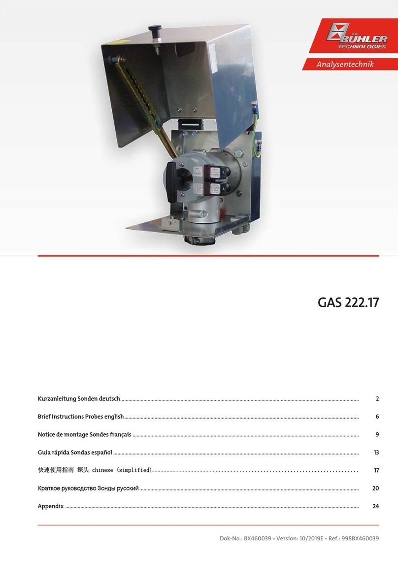
Buhler GAS 222.10 Owner's manual

Gas Analysis
Installation and Operation Instructions
Original instructions
Sample gas probes
GAS 222.10
BE460036
10/2019
Bühler Technologies GmbH, Harkortstr. 29, D-40880 Ratingen
Tel. +49 (0) 21 02 / 49 89-0, Fax: +49 (0) 21 02 / 49 89-20
E-Mail: [email protected]
Internet: www.buehler-technologies.com

Bühler Technologies GmbH, Harkortstr. 29, D-40880 Ratingen
Tel. +49 (0) 21 02 / 49 89-0, Fax: +49 (0) 21 02 / 49 89-20
Internet: www.buehler-technologies.com
E-Mail: [email protected]
Read this instruction carefully prior to installation and/or use. Pay at-
tention particularly to all advises and safety instructions to prevent in-
juries. Bühler Technologies can not be held responsible for misusing
the product or unreliable function due to unauthorised modifications.
All rights reserved. Bühler Technologies GmbH 2023
Document information
Document No......................................................... BE460036
Version..........................................................................10/2019

GAS 222.10
Table of Contents
1 Introduction.....................................................................................................................................................................................................................2
1.1 Intended Use.........................................................................................................................................................................................................2
1.2 Type Plate...............................................................................................................................................................................................................2
1.3 Scope of Delivery..................................................................................................................................................................................................2
1.4 Ordering instructions.........................................................................................................................................................................................2
1.5 Product Description............................................................................................................................................................................................ 2
2 Safety instructions ......................................................................................................................................................................................................... 3
2.1 Important Information...................................................................................................................................................................................... 3
2.2 General Hazard Warnings ................................................................................................................................................................................4
3 Transport and storage ..................................................................................................................................................................................................6
4 Installation and connection ........................................................................................................................................................................................ 7
4.1 Installation site requirements......................................................................................................................................................................... 7
4.2 Installation ............................................................................................................................................................................................................ 7
4.3 Installing the sampling tube (optional)........................................................................................................................................................ 7
4.4 Installing the downstream filter.....................................................................................................................................................................8
4.5 Connecting the Gas Line....................................................................................................................................................................................8
4.5.1 Connecting the calibrating gas line (optional)............................................................................................................................8
4.6 Electrical Connections........................................................................................................................................................................................9
5 Operation and Control................................................................................................................................................................................................10
5.1 Before Start-Up ..................................................................................................................................................................................................10
6 Maintenance...................................................................................................................................................................................................................11
6.1 Maintaining the Filter Element..................................................................................................................................................................... 12
6.1.1 Replacing the downstream filter................................................................................................................................................... 12
6.1.2 Replacing the Outlet Filter with Micro-Fibreglass Filter Element........................................................................................ 13
6.2 Maintenance Schedule .................................................................................................................................................................................... 13
7 Service and repair......................................................................................................................................................................................................... 14
7.1 Troubleshooting ................................................................................................................................................................................................ 14
7.2 Spare Parts and Accessories ........................................................................................................................................................................... 14
8 Disposal ............................................................................................................................................................................................................................15
9 Appendices ..................................................................................................................................................................................................................... 16
9.1 Technical Data.................................................................................................................................................................................................... 16
9.2 Flow chart ............................................................................................................................................................................................................ 16
9.3 Dimensions ..........................................................................................................................................................................................................17
9.4 User book (Please make copies)..................................................................................................................................................................... 18
10 Attached Documents...................................................................................................................................................................................................19
iBühler Technologies GmbHBE460036 ◦ 10/2019

GAS 222.10
1 Introduction
1.1 Intended Use
The sample gas probe is intended for installation into gas analysis systems in commercial applications.
Sample gas probes are among the main components in a gas conditioning system.
– Therefore also note the related drawing in the data sheet in the appendix.
– Before installing the device, verify the listed technical data meet the application parameters.
– Further verify all contents are complete.
Please refer to the type plate to identify your model. In addition to the job number/ID number, this also contains the article
number and model designation.
Please note the specific values of the device when connecting, and the correct versions when ordering spare parts.
1.2 Type Plate
Example:
GAS 222.10
100107323 462221009902000112213 001
230V 50/60Hz 440W
material: 1.4571/1.4408/PTFE
Read manual!
Manufacturer and address
Model designation
Order no., Item no.
Material
Voltage
1.3 Scope of Delivery
– 1 x Sample gas probe
– 1 x Flange gasket and screws
– Product documentation
– Connection and mounting accessories (only optional)
1.4 Ordering instructions
The item number is a code for the configuration of your unit. Please use the following model key:
4622210 0 9 9 0 0 X 0 0 9 9 9 9 9 9 Product Characteristics
Flange/approval
DIN DN65 PN6
Power supply sample probe
none
Calibrating gas connection
0 No calibrating gas connection
1 6 mm
2 6 mm + check valve
3 1/4"
4 1/4" + check valve
1.5 Product Description
Probe Description
GAS 222.10 Probe with downstream filter
Accessories Please refer to the data sheet at the end of this manual for accessories for this probe
2 Bühler Technologies GmbH BE460036 ◦ 10/2019

GAS 222.10
2 Safety instructions
2.1 Important Information
This unit may only be used if:
– The product is being used under the conditions described in the operating- and installation instructions, used according to
the nameplate and for applications for which it is intended. Any unauthorized modifications of the device will void the war-
ranty provided by Bühler Technologies GmbH,
– Complying with the threshold values specified in the data sheet and the instructions,
– Equipment is operated in intrinsically safe electric circuits.
– The controller itself is installed outside the explosive area,
– Monitoring equipment / protection devices must be connected correctly,
– Service and repair work not described in these instructions are performed by Bühler Technologies GmbH,
– Using genuine replacement parts.
– Erecting electrical systems in explosive areas requires compliance with regulation EN 60079-14.
– Additional national regulations pertaining to initial operation, operation, maintenance, repairs and disposal must be ob-
served.
– These operating instructions are a part of the equipment. The manufacturer reserves the right to change performance-, spe-
cification- or technical data without prior notice. Please keep these instructions for future reference.
Signal words for warnings
DANGER
Signal word for an imminent danger with high risk, resulting in severe injuries or death if not avoided.
WARNING
Signal word for a hazardous situation with medium risk, possibly resulting in severe injuries or death if not
avoided.
CAUTION
Signal word for a hazardous situation with low risk, resulting in damaged to the device or the property or
minor or medium injuries if not avoided.
NOTICE
Signal word for important information to the product.
Warning signs
These instructions use the following warning signs:
Warns of a general hazard General information
Warns not to inhale toxic gasses Wear respiratory equipment
Warns of corrosive liquids Wear a safety mask
Warns of explosive areas Wear gloves
3Bühler Technologies GmbHBE460036 ◦ 10/2019

GAS 222.10
2.2 General Hazard Warnings
The maximum surface temperatures of the probes also vary based on operating conditions (steam temperature, sample gas in-
let temperature, ambient temperature, fluid flow rate). When used in explosive areas, also particularly note the related hazard
warnings.
The equipment must be installed by a professional familiar with the safety requirements and risks.
Be sure to observe the safety regulations and generally applicable rules of technology relevant for the installation site. Prevent
malfunctions and avoid personal injuries and property damage.
The operator of the system must ensure:
– Safety notices and operating instructions are available and observed,
– The respective national accident prevention regulations are observed,
– The permissible data and operational conditions are maintained,
– Safety guards are used and mandatory maintenance is performed,
– Legal regulations are observed during disposal,
– compliance with national installation regulations.
Maintenance, Repair
Please note during maintenance and repairs:
– Repairs to the unit must be performed by Bühler authorised personnel.
– Only perform conversion-, maintenance or installation work described in these operating and installation instructions.
– Always use genuine spare parts.
– Do not install damaged or defective spare part. If necessary, visually inspect prior to installation to determine any obvious
damage to the spare parts.
Always observe the applicable safety and operating regulations in the respective country of use when performing any type of
maintenance.
NOTICE When used in explosive areas
The basic version of the probe is not suitable for use in Zone 1 or 21 explosive areas. The
accessories selected (e.g. add-on parts such as solenoid valves, heated blowback vessel...)
may severely limit the approved applications.
When using category 3G or 3D accessories, the are of application for the probe is limited
to Zone 2 or Zone 22. Therefore be sure to note the type plates for all add-on parts. Partic-
ularly pay attention to the ignition protection markings and all hazard warnings in this
manual.
DANGER Toxic, corrosive gas/condensate
Sample gas/condensate may be hazardous to health.
a) If necessary, ensure a safe gas/condensate discharge.
b) Always disconnect the gas supply when performing maintenance or repairs.
c) Protect yourself from toxic/corrosive gasses/condensate when performing mainten-
ance. Wear appropriate protective equipment.
DANGER Explosion hazard
Life and explosion risk may result from gas leakage due to improper use.
a) Use the devices only as described in this manual.
b) Regard the process conditions.
c) Check tubes and hoses for leakage.
4 Bühler Technologies GmbH BE460036 ◦ 10/2019

GAS 222.10
DANGER
Use in explosive areas
Flammable gasses and dust could ignite or explode. Avoid the following hazard sources:
Sparking!
Protect the equipment from external blows.
Flame propagation!
If the process holds a risk of flame propagation, install a flame arrestor.
Dust:
If possible, take the electrical components which must be opened for repair to a dust-
free room. If unable to do so, prevent dust from entering the housing.
Ignition of dust layers!
When using the device in a dusty environment, routinely clean dust from all compon-
ents. Also remove layers of dust in inaccessible areas.
DANGER Dangerous electrostatic charge (explosion hazard)
Incendive electrostatic charges may occur when cleaning plastic housing parts and
decals (e.g. with a dry cloth or compressed air). The sparks this produces could ignite
flammable, explosive atmospheres.
Always clean plastic housing parts and decals with a damp cloth!
DANGER Explosion hazard due to high liquid temperatures
Hot steam and hot sample gas cause in a high probe surface temperature. The highest
fluid temperature is approximately the maximum probe surface temperature.
a) Always ensure a safety clearance of at least 20 K between the fluid temperature
(steam, sample gas) and ignition temperature of explosive atmosphere (by measur-
ing and monitoring the temperature).
b) Also be sure to stay well below the smouldering temperatures of dust.
c) Observe the relevant requirements in standards regarding the max. permissible sur-
face temperature and ignition temperature of explosive atmosphere.
5Bühler Technologies GmbHBE460036 ◦ 10/2019
GAS 222.10
3 Transport and storage
Only transport the product inside the original packaging or a suitable alternative.
The equipment must be protected from moisture and heat when not in use. They must be stored in a covered, dry and dust-free
room at a temperature between -20°C to 50°C (-4°F to 122°F).
6 Bühler Technologies GmbH BE460036 ◦ 10/2019

GAS 222.10
4 Installation and connection
4.1 Installation site requirements
Sample gas probes are intended for flange mounting.
– Installation site and installation position are determined based on requirements specific to the application.
– If necessary, the connection piece should be slightly tilted toward the centre of the channel.
– The installation site should be protected from the weather.
– In addition, adequate and safe access for installation and future maintenance work should be provided. Particularly follow
the uninstalled size of the probe tube!
If the probe is transported to the installation site in pieces, it will first need to be assembled.
4.2 Installation
DANGER Danger to life and explosion during installation and maintenance
The unit must not be worked on (assembly, installation, maintenance) in explosive at-
mospheres.
DANGER Explosion hazard
When used in explosive areas
Flammable gasses and dust could ignite or explode.
Never operate the gas probe outside the specifications. Extracting gases or gas mixtures
which are also explosive in the absence of air is prohibited.
DANGER Explosion hazard due to ignition of dust
When using the device in a dusty environment, routinely clean dust from all compon-
ents.
The ignition temperature resp. smouldering temperature of flammable dusts resp. dust
layers present must be considerably higher than the maximum surface temperature of
the device (observe applicable standards and statutory regulations).
If possible, take the electrical components which must be opened for repair to a dust-
free room. If unable to do so, prevent dust from entering the housing.
DANGER Explosion hazard due to flame propagation
Severe injuries and damage to the system
If the process holds a risk of flame propagation, install a flame arrestor.
DANGER Dangerous electrostatic charge (explosion hazard)
Incendive electrostatic charges may occur when cleaning plastic housing parts and
decals (e.g. with a dry cloth or compressed air). The sparks this produces could ignite
flammable, explosive atmospheres.
Always clean plastic housing parts and decals with a damp cloth!
4.3 Installing the sampling tube (optional)
The sampling tube, if necessary with the fitting extension, must be screwed in. The probe is then attached to the mating flange
using the included seal and nuts.
7Bühler Technologies GmbHBE460036 ◦ 10/2019
GAS 222.10
4.4 Installing the downstream filter
NOTICE
The downstream filter and the O-ring for the handle must be inserted prior to first star-
tup.
Operating without downstream filter prohibited!
O-ring handle
Attach an O-ring suitable for the expected ambient temperature to the handle.
Attach the downstream filter to the handle. Then carefully insert the handle with
filter in the gas probe and turn 90° to secure.
Verify the handle is seated correctly. When seated correctly it locks onto the filter
housing.
4.5 Connecting the Gas Line
The sample gas line must be carefully and properly connected using a suitable fitting.
This table provides an overview of the sample gas probe connections:
Probe
GAS 222
Reservoir
PAV01
Ball valve
pneumatic drive
Control valve
3/2-way solenoid
valve
Connecting flange 1) DN65/PN6/
DN3“-150 2)
Sample gas inlet G3/4
Sample gas outlet NPT 1/4
Blowback connection G3/8
Test gas connection 1) Tube Ø6 mm
Tube Ø1/4 2)
Filling port NPT 1/4
Condensate G1/2
Bypass NPT 1/4
Control air G1/8 G1/4
NPT 1/4
Tab.1: Gas Probe Connections (Varies by Model)
1) Varies by version.
2) Only GAS 222.xx ANSI and GAS 222.xx AMEX
WARNING Gas emanation
Sample gas can be harmful to the health!
Check the lines for leaks.
4.5.1 Connecting the calibrating gas line (optional)
Connecting the calibrating gas line requires a Ø6 mm or Ø1/4” pipe fitting.
If the calibrating gas connection was ordered with check valve, a Ø6 mm or Ø1/4” pipe can be connected directly to the check
valve.
8 Bühler Technologies GmbH BE460036 ◦ 10/2019

GAS 222.10
4.6 Electrical Connections
DANGER Explosion hazard due to absence of potential equalisation
The device must be connected to potential equalisation (earthed) at the designated
points.
Please observe the local regulations and guidelines.
9Bühler Technologies GmbHBE460036 ◦ 10/2019

GAS 222.10
5 Operation and Control
NOTICE
The device must not be operated beyond its specifications.
5.1 Before Start-Up
Before starting the device, verify
– the hose- and electrical connections are not damaged and correct installed.
– no parts of the gas probe have been removed.
– the safety and monitoring devices are installed and functional.
– the gas inlet and outlet of the gas probe are open.
– ambient parameters are met.
– the performance specifications in the type plate are met.
– voltage and frequency in the type plate match the mains values.
– all connection cables are installed without strain.
– precautions have been taken.
– cable glands are sealed properly.
– the earth is proper and functional.
When used in Ex areas, also verify the probe and all add-on parts are suitable for use (observe type plates and ignition
protection markings) and compliance with applicable Ex regulations.
10 Bühler Technologies GmbH BE460036 ◦ 10/2019

GAS 222.10
6 Maintenance
During maintenance, remember:
– The equipment must be maintained by a professional familiar with the safety requirements and risks.
– Only perform maintenance work described in these operating and installation instructions.
– When performing maintenance of any type, observe the respective safety and operation regulations.
DANGER Danger to life and explosion during installation and maintenance
The unit must not be worked on (assembly, installation, maintenance) in explosive at-
mospheres.
DANGER Toxic, corrosive gases
The measuring gas led through the equipment can be hazardous when breathing or
touching it.
a) Check tightness of the measuring system before putting it into operation.
b) Take care that harmful gases are exhausted to a save place.
c) Before maintenance turn off the gas supply and make sure that it cannot be turned
on unintentionally.
d) Protect yourself during maintenance against toxic / corrosive gases. Use suitable pro-
tective equipment.
CAUTION Hot surface
Risk of burns
Depending on the operating parameters, the housing temperature may reach over 100
°C during operation.
Allow the unit to cool down before performing maintenance.
DANGER Explosion hazard due to ignition of dust
When using the device in a dusty environment, routinely clean dust from all compon-
ents.
The ignition temperature resp. smouldering temperature of flammable dusts resp. dust
layers present must be considerably higher than the maximum surface temperature of
the device (observe applicable standards and statutory regulations).
If possible, take the electrical components which must be opened for repair to a dust-
free room. If unable to do so, prevent dust from entering the housing.
11Bühler Technologies GmbHBE460036 ◦ 10/2019
GAS 222.10
6.1 Maintaining the Filter Element
The probes feature a particle filter which needs to be changed as it becomes dirty.
To do so, disconnect the voltage supply and if applicable close the shut-off valve to the process or switch off the process.
CAUTION!Do not damage the rear filter seat.
NOTICE
Ceramic filter elements are very brittle by nature. Handle them with care, don’t let them
fall.
Filter elements made out of sintered stainless steel can be cleaned in an ultrasonic bath
and be used several times as long as both seals are still in proper conditions.
DANGER Toxic, corrosive gases
The measuring gas led through the equipment can be hazardous when breathing or
touching it.
a) Check tightness of the measuring system before putting it into operation.
b) Take care that harmful gases are exhausted to a save place.
c) Before maintenance turn off the gas supply and make sure that it cannot be turned
on unintentionally.
d) Protect yourself during maintenance against toxic / corrosive gases. Use suitable pro-
tective equipment.
DANGER Explosion hazard due to high liquid temperatures
Hot steam and hot sample gas cause in a high probe surface temperature. The highest
fluid temperature is approximately the maximum probe surface temperature.
a) Always ensure a safety clearance of at least 20 K between the fluid temperature
(steam, sample gas) and ignition temperature of explosive atmosphere (by measur-
ing and monitoring the temperature).
b) Also be sure to stay well below the smouldering temperatures of dust.
c) Observe the relevant requirements in standards regarding the max. permissible sur-
face temperature and ignition temperature of explosive atmosphere.
6.1.1 Replacing the downstream filter
– Turn the handle at the back end of the probe by 90° (handle must then be horizontal), pushing in slightly, and remove.
– Remove the dirty filter element and check the sealing surfaces.
– Before installing the new filter element, replace the seal on the handle plug (seal included with the filter element).
– Then carefully insert the handle with new filter, push in slightly and turn 90° (handle must then be vertical). Pull on the
handle to verify the filter element is firmly seated.
– With the filter removed, if necessary also need clean the inside of the sampling tube by blowing it out or using a cleaning
wand.
12 Bühler Technologies GmbH BE460036 ◦ 10/2019

GAS 222.10
6.1.2 Replacing the Outlet Filter with Micro-Fibreglass Filter Element
– Turn the handle at the rear end of the probe by 90° (handle must be horizontal), pushing in slightly, and remove.
– Unscrew the dirty filter element counter-clockwise from the thread of the handle.
– Pull both stainless steel filter seats off the filter element.
– Before installing the new filter element, replace the seal on the handle and inside the stainless steel filter seats (seals are in-
cluded with the filter element).
– Then turn the handle with the new filter by 90° (handle must be vertical), pushing in slightly.
CAUTION!Do not damage the rear filter seat.
Filter element
Stainless steel filter seat
(with two interior O-rings)
Thread Handle
With the filter removed, you may also clean the inside of the sampling tube if necessary by blowing it out or using a cleaning
wand.
6.2 Maintenance Schedule
NOTICE
When using the probe in explosive areas the maintenance schedule must be observed!
Maintenance schedule for normal ambient conditions:
Component Interval in operating hours Work to be performed To be performed by
Entire probe every 8000 h – Check gas connections
– Proper function, dirt.
If damaged, replace or have repaired by Bühler.
Operator
Entire probe based on dust level
(layer must be <3mm)
– Remove dust. Operator
Filter every 8,000 h – Check dirt level of filter. Operator
Seals every 8,000 h – Replace O-rings.
– Replace seals after every filter change.
Operator
Entire probe after 20,000h or 3years Inspection by Bühler Service technician/Bühler
13Bühler Technologies GmbHBE460036 ◦ 10/2019
GAS 222.10
7 Service and repair
This chapter contains information on troubleshooting and correction should an error occur during operation.
Repairs to the unit must be performed by Bühler authorised personnel.
Please contact our Service Department with any questions:
Tel.: +49-(0)2102-498955 or your agent
If the equipment is not functioning properly after correcting any malfunctions and switching on the power, it must be inspected
by the manufacturer. Please send the equipment inside suitable packaging to:
Bühler Technologies GmbH
- Reparatur/Service -
Harkortstraße 29
40880 Ratingen
Germany
Please also attach the completed and signed RMA decontamination statement to the packaging. We will otherwise be unable to
process your repair order.
You will find the form in the appendix of these instructions, or simply request it by e-mail:
7.1 Troubleshooting
CAUTION Risk due to defective device
Personal injury or damage to property
a) Switch off the device and disconnect it from the mains.
b) Repair the fault immediately. The device should not be turned on again before elim-
ination of the failure.
Problem / Malfunction Possible cause Action
No or reduced gas flow – Filter element clogged – Clean or replace filter element
– Gas circuit clogged – Clean sampling tube
– Check compressed air supply
Tab.2: Troubleshooting
7.2 Spare Parts and Accessories
Please also specify the model and serial number when ordering parts.
Upgrade and expansion parts can be found in our catalog.
Available spare parts:
Item no. Description
90 090 79 Flange seal DN65 PN6
90 090 68 Flange seal FD 40 WS
46 222 012 O-ring kit for filter element and probe, material: Viton
46 222 024 O-ring kit for filter element and probe, material: Perfluoroelastomer
Please see the accessories data sheet in the appendix for filter elements
14 Bühler Technologies GmbH BE460036 ◦ 10/2019

GAS 222.10
8 Disposal
The applicable national laws must be observed when disposing of the products. Disposal must not result in a danger to health
and environment.
The crossed out wheelie bin symbol on BühlerTechnologiesGmbH electrical and electronic products indicates special disposal
notices within the European Union (EU).
The crossed out wheelie bin symbol indicates the electric and electronic products bearing the symbol
must be disposed of separate from household waste. They must be properly disposed of as waste elec-
trical and electronic equipment.
BühlerTechnologiesGmbH will gladly dispose of your device bearing this mark. Please send your
device to the address below for this purpose.
We are obligated by law to protect our employees from hazards posed by contaminated devices. Therefore please understand
that we can only dispose of your waste equipment if the device is free from any aggressive, corrosive or other operating fluids
dangerous to health or environment. Please complete the "RMA Form and Decontamination Statement", available on our web-
site, for every waste electrical and electronic equipment. The form must be applied to the packaging so it is visible from the
outside.
Please return waste electrical and electronic equipment to the following address:
Bühler Technologies GmbH
WEEE
Harkortstr. 29
40880 Ratingen
Germany
Please also observe data protection regulations and remember you are personally responsible for the returned waste equipment
not bearing any personal data. Therefore please be sure to delete your personal data before returning your waste equipment.
15Bühler Technologies GmbHBE460036 ◦ 10/2019

GAS 222.10
9 Appendices
9.1 Technical Data
Gas Probe Technical Data
Operating temperature: max. 200 °C
Max. operating pressure: 6 bar
Parts in contact with media: Flange: 1.4571
Seals: Graphite/1.4404 and see filter
9.2 Flow chart
16 Bühler Technologies GmbH BE460036 ◦ 10/2019

GAS 222.10
9.3 Dimensions
17Bühler Technologies GmbHBE460036 ◦ 10/2019

GAS 222.10
9.4 User book (Please make copies)
Maintained on Unit no. Operating hours Remarks Signature
18 Bühler Technologies GmbH BE460036 ◦ 10/2019
Table of contents
Other Buhler Industrial Equipment manuals

Buhler
Buhler GAS 222.31 Owner's manual

Buhler
Buhler GAS 222.20 DH Owner's manual

Buhler
Buhler SnackFix User manual

Buhler
Buhler BuhlerVision HMT-1 User manual

Buhler
Buhler GAS 222.17 Reference guide

Buhler
Buhler SZLH-400b User manual

Buhler
Buhler SDW 800/1000 User manual

Buhler
Buhler RC 1.1 User manual

Buhler
Buhler TS 10 Reference guide

Buhler
Buhler GAS 222.21 Ex1 Reference guide