ABB GE ReliaGear AMP1 User manual

INSTALLATION INSTRUCTIONS
ReliaGear™lighting panelboard -
AMP1 integrated power and energy


Table of contents
AMP1
4 Safety
5 Specifications
6 Product identification
7 Product diagram
7 Wiring diagram symbols
8 Wiring
9 Control power
10 Pulse contact inputs
10 User interface menu abbreviation
11 User interface for data configuration
12 Alert/reset information
13 User interface for setup
15 RS-485 communications
15 Display screen diagram
16 Quick setup
17 BACnet default settings
17 BACnet programming information
19 Device object
20 Analog_value objects
21 Analog_input objects
23 Binary_input objects
24 Data logging
25 Trend_log objects
26 Installation
27 Supported system types
28 Troubleshooting
AMP1N4
29 Enclosure for AMP1 series energy
meters with swing panel kit
30 Product overview
31 Installation

4AMP1 INTEGRATED POWER AND ENERGY INSTALLATION INSTRUCTIONS
For troubleshooting or service related questions, contact ABB at 800-782-8061 or at epis.componen[email protected]
AMP1
Safety
FCC PART 15 INFORMATION NOTE: This equipment has been
tested by the manufacturer and found to comply with the
limits for a class B digital device, pursuant to part 15 of the
FCC Rules. These limits are designed to provide reasonable
protection against harmful interference when the equipment
is operated in a residential environment. This equipment
generates, uses, and can radiate radio frequency energy and, if
not installed and used in accordance with the instruction
manual, may cause harmful interference to radio
communications. This device complies with part 15 of the FCC
Rules.
Operation is subject to the following two conditions:
(1) This device may not cause harmful interference, and
(2) This device must accept any interference received,
including interference that may cause undesired operation.
Modifications to this product without the express
authorization of the manufacturer nullify this statement.
A qualified person is one who has skills and knowledge related
to the construction and operation of this electrical equipment
and the installation, and has received safety training to
recognize and avoid the hazards involved.
NEC2011 Article 100: No responsibility is assumed by
manufacturer for any consequences arising out of the use of
this material.Control system design must consider the
potential failure modes of control paths and, for certain
critical control functions, provide a means to achieve a safe
state during and after a path failure. Examples of critical
control functions are emergency stop and over-travel stop.
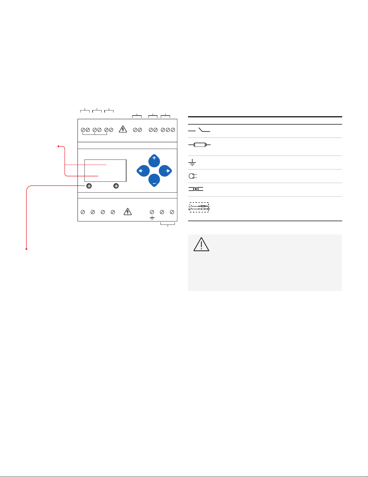
This symbol indicates an electrical shock
hazard exists.
Documentation must be consulted where this
symbol is used on the product.
DANGER: Hazard of Electric Shock, Explosion or Arc
Flash Failure to follow these instructions will result in
death or serious injury.
• Follow safe electrical work practices. See NFPA 70E in
the USA, or applicable local codes.
• This equipment must only be installed and serviced by
qualified electrical personnel.
• Read, understand and follow the instructions before
installing this product.
• Turn off all power supplying equipment before working
on or inside the equipment.
• Use a properly rated voltage sensing device to confirm
power is off. DO NOT DEPEND ON THIS PRODUCT FOR
VOLTAGE INDICATION
• Only install this product on insulated conductors
WARNING: Loss of Control
• Failure to follow these instructions may cause injury,
death or equipment damage.
• Assure that the system will reach a safe state during and
after a control path failure.
• Separate or redundant control paths must be provided
for critical control functions.
• Test the effect of transmission delays or failures of
communication links.
• Each implementation of equipment using
communication links must be individually and
thoroughly tested for proper operation before placing it
in service.a
NOTICE:
• This product is not intended for life or safety
applications.
• Do not install this product in hazardous or classified
locations.
• The installer is responsible for conformance to all
applicable codes
• Mount this product inside a suitable fire and electrical
enclosure.

5
AMP1 INTEGRATED POWER AND ENERGY INSTALLATION INSTRUCTIONS
For troubleshooting or service related questions, contact ABB at 800-782-8061 or at epis.componen[email protected]
AMP1
Specifications
Measurement accuracy
Real Power/Energy
Reactive Power/Energy
Current
Voltage
L-NL-L
Sample Rate
Data Update Rate
Type of Measurement
One to three phase AC system
Input voltage
Measured AC
L-LL-N)
L-N
Metering Over-Range
Impedance L-NL-L
Frequency
Input current
CT Scaling
Measured Input Range
Impedance
Control power
AC
L-LL-N)
L-N
DC¹
Ride Through
Input
Pulse Solid-state or mechanical contacts (currents
Output
Mechanical
IP Degree of Protection
Display Characteristics Back-lit blue LCD
Terminal Block Screw
Torque
)
Rail
Environmental
Operating Temp Range
Storage Temp Range
Humidity Range
Altitude of Operation
Metering
North America
L-NL-L
CE L-N
Conducted and
Radiated Emissions
Class B (residential and light industrial)
Conducted and
Radiated Immunity
Compliance
Agency approvals
US and Canada (cULus)
Europe (CE)
¹ External DC current limiting is required, see fuse recommendations.

6AMP1 INTEGRATED POWER AND ENERGY INSTALLATION INSTRUCTIONS
For troubleshooting or service related questions, contact ABB at 800-782-8061 or at epis.componen[email protected]
AMP1
Product identification
Dimensions
DIN mount configuration
Bottom view
Screw mount configuration
Bottom view
(107mm)
4.2" (91mm)
3.6"
(39mm)
1.5
(59mm)
2.3"
(48mm)
1.9"
(45mm)
1.8"
(91 mm)
3.6"
(107 mm)
4.2"
(4 mm)
0.2"
(99 mm)
3.9"
(61 mm)
2.4"
++
+
4.3"
(109 mm)
1.2"
(31 mm) 0.3"
(8 mm)
0.4"
(10 mm)
(107mm)
4.2" (91mm)
3.6"
(39mm)
1.5
(59mm)
2.3"
(48mm)
1.9"
(45mm)
1.8"
(91 mm)
3.6"
(107 mm)
4.2"
(4 mm)
0.2"
(99 mm)
3.9"
(61 mm)
2.4"
++
+
4.3"
(109 mm)
1.2"
(31 mm) 0.3"
(8 mm)
0.4"
(10 mm)
(107mm)
4.2" (91mm)
3.6"
(39mm)
1.5
(59mm)
2.3"
(48mm)
1.9"
(45mm)
1.8"
(91 mm)
3.6"
(107 mm)
4.2"
(4 mm)
0.2"
(99 mm)
3.9"
(61 mm)
2.4"
++
+
4.3"
(109 mm)
1.2"
(31 mm) 0.3"
(8 mm)
0.4"
(10 mm)
BACnet MS/TP protocol
Modbus full data set, data logging
pulse input (2 pulses)
Description
AMP1H5
Product overview
The AMP1H5 DIN Rail Power Meter provides a solution for
measuring energy data with a single device. Inputs include
Control Power, CT, and 3-phase voltage. The meter supports
BACnet MS/TP protocol and has data logging capability and
two pulse contact inputs. The LCD screen on the faceplate
allows instant output viewing.
The meter is housed in a plastic enclosure suitable for
installation on T35 DIN rail according to EN50022. It can be
mounted with any orientation over the entire ambient
temperature range, either on a DIN rail or in a panel. The
AMP1H5 meter is not sensitive to CT orientation to reduce
installation errors.
Data output
Full Data Set (FDS)
•
•
• Configurable for CT & PT ratios, system type, and passwords
• Diagnostic alerts
• Current: 3-phase average
• Volts: 3-phase average
• Current: by phase
• Volts: by phase Line-Line and Line-Neutral
• Power: Real, Reactive, and Apparent 3-phase total and per
phase
• Power factor: 3-phase average and per phase
• Frequency
• Power demand: most Recent and Peak
• Demand configuration: Fixed, Rolling Block, and External
Sync (Modbus only)
• Real Time Clock: uses BACnet Time Synchronization services
Data logging (includes all FDS outputs, plus)
• 3 BACnet Log_Events: each buffer holds 5760 time-stamped
• 32-bit entries (user configures which 3 data points are
stored in these buffers)
• User configurable logging interval (when configured for a 15
minute interval, each buffer holds 60 days of data)
• • Continuous and Single Shot logging modes: user selectable

7
AMP1 INTEGRATED POWER AND ENERGY INSTALLATION INSTRUCTIONS
For troubleshooting or service related questions, contact ABB at 800-782-8061 or at epis.componen[email protected]
AMP1
Product diagram and wiring diagram symbols
To avoid distortion, use parallel wires for control power and
voltage inputs. The following symbols are used in the wiring
diagrams on the following pages.
CAUSION: RISK OF EQUIPMENT DAMAGE
• This product is designed only for use with 1V or
0.33V current transducers (CTs).
• DO NOT USE CURRENT OUTPUT (e.g. 5A) CTs ON
THIS PRODUCT.
• Failure to follow these instructions can result in
overheating and permanent equipment damage.
Shield
Two 5-character
rows of display text.
• Top row
alphanumeric
• Bottom row
numeric only
The red alarm LED lights when any of the 3 phase voltages drop below the
selected threshold: The green Energy LED lights when the pulse 1 input
contacts are active or closed.
1234.5
Alarm Energy
Pulse Inputs RS-485
BACnet
(X2)A(X1)(X2) B(X1)(X2) C(X1)
IA
IB
IC
X2 X1X2 X1X2 X1
CT Inputs
1 or 0.333 VAC
0.1A 50/60 Hz
12
VA
VB
VC
Neutral
Earth
Control
Power
UL: 90VL-N
- 600V
L-L
CE: 90V
L-N - 300V
L-N
VOLTAGE INPUTS
CAT III 50/60 Hz
1
A B C N
2
Pulse input 1
Pulse input 2
Symbol Description
Voltage disconnect switch
Fuse (Installer is responsible for ensuring compliance
with local requirements. No fuses are included
with the meter.)
Earth ground
Current transducer
Potential transformer
Protection containing a voltage disconnect switch with
a fuse or disconnect circuit breaker. The protection
device must be rated for the available short-circuit
current at the connection point.
X2
X1
X2
X1
X2
X1
X2
X1
X2
X1
X2
X1

8AMP1 INTEGRATED POWER AND ENERGY INSTALLATION INSTRUCTIONS
For troubleshooting or service related questions, contact ABB at 800-782-8061 or at epis.componen[email protected]
WARNING: RISK OF ELECTRIC SHOCK OR
PERMANENT EQUIPMENT DAMAGE
Failure to follow these instructions will result in
death or serious injury.
CT negative terminals are referenced to the meter’s
neutral and may be at elevated voltages.
• Do not contact meter terminals while unit is
connected.
• Do not connect or short other circuits to the CT
terminals.
Figure 1.
1-phase, line to neutral, 2-wire system, 1 CT
Figure 2.
1-phase, line to line, 2-wire system, 1 CT
USE SYSTEM TYPE 11 (2L)
Figure 3.
1-phase, direct voltage, 2-wire system connection, 2 CT
AMP1
Wiring
X2
X1 White
Black
C
A
B
N
A
B
C
+
-
+
-
+
-
L1 L2
X2
X1 White
Black
C
A
B
N
A
B
C
+
-
+
-
+
-
N L1
X2
X1 White
Black
C
A
B
N
A
B
C
+
-
+
-
+
-
L1 L2
X2
X1 White
Black
C
A
B
N
A
B
C
+
-
+
-
+
-
N L1
Figure 4.
3-phase, 3-wire system connection, CT no PT
USE SYSTEM TYPE 31 (3L)
Figure 5.
3-phase, 4-wire, wye direct voltage input connection, 3 CT
Figure 6.
3-phase, 4-wire, wye connection, 3 CT 3 PT
L1 L2
X2
X1
X2
X1
C
A
B
N
A
B
C
+
-
+
-
+
-
N
White
Black
White
Black
X2
X1
L1 L2 L3
C
A
B
N
A
B
C
X2
X1
X2
X1
+
-
+
-
+
-
White
Black
White
Black
White
Black
X2
X1
C
A
B
N
A
B
C
X2
X1
X2
X1
+
-
+
-
+
-
White
Black
White
Black
White
Black
White
Black
White
White
Black
Black
X2
X1
N L1 L2 L3
C
A
B
N
A
B
C
X2
X1
X2
X1
+
-
+
-
+
-
N L1 L2 L3

9
AMP1 INTEGRATED POWER AND ENERGY INSTALLATION INSTRUCTIONS
For troubleshooting or service related questions, contact ABB at 800-782-8061 or at epis.componen[email protected]
Direct connect control power, line to line
Line to Line from 90 VAC to 600 VAC (UL) (520 VAC for CE). In
UL installations the lines may be floating (such as a delta). If
any lines are tied to an earth (such as a corner grounded delta),
see the line to neutral installation limits. In CE compliant
installations, the lines must be neutral (earth) referenced at
less than 300VACL-N.
Direct connect control power, line to neutral
Line to neutral from 90 VAC to 347 VAC (UL) or 300 VAC (CE).
Direct connect control power (DC control power)
DC control power from 125 VDC to 300 VDC (UL and CE max.)
AMP1
Control power
L1
G 1 2
L2 L3
N L1 L2 L3
G 1 2
1 2G
N L1 L2 L3
G 1 2
L1
G 1 2
L2 L3
N L1 L2 L3
G 1 2
1 2G
N L1 L2 L3
G 1 2
L1
G 1 2
L2 L3
N L1 L2 L3
G 1 2
1 2G
N L1 L2 L3
G 1 2
Control power transformer (CPT) connection
The control power transformer may be wired L-N or L-L. Output
to meet meter input requirements.
Fuse recommendations
Keep the fuses close to the power source (obey local and
national code requirements).
For selecting fuses and circuit breakers, use the following
criteria:
• Select current interrupt capacity based on the installation
category and fault current capability.
• Select over-current protection with a time delay.
• Use a voltage rating sufficient for the input voltage applied.
• Provide overcurrent protection and disconnecting means to
protect the wiring. For DC installations, provide external
circuit protection. Suggested: 0.5A, time delay fuses rated
for DC operation at or above the supply voltage.
• Use the earth connection for electromagnetic compatibility
(EMC), not a protective earth ground.
L1
G 1 2
L2 L3
N L1 L2 L3
G 1 2
1 2G
N L1 L2 L3
G 1 2

10 AMP1 INTEGRATED POWER AND ENERGY INSTALLATION INSTRUCTIONS
For troubleshooting or service related questions, contact ABB at 800-782-8061 or at epis.componen[email protected]
The AMP1H5 has two inputs with pulse accumulators for solid
state or mechanical contacts in other sensors, such as water
or gas ¯ow meters. These inputs are isolated from the
measured circuits and referenced to the communication signal
ground. Use with contacts that do not require current to
remove oxidation.
The user can set the display mode to IEC or IEEE notation in
the SETUP menu.
AMP1
Pulse contact inputs and user interface menu abbreviations
Comm S
output
+
~10 kΩ
Comm
ground
4-10
VDC
nominal
Equivalent
circuit
Pulse input
contacts
~
=
~
=
≤ 100 mA
≤ 100 mA
≤ 100 mA
~
=
Alarm Energy Output
+ – S
LOAD
LOAD
LOAD
Over-current protective
device¹ (not supplied)
3-30 VDC
Power source²
6-30 VAC
(AMP1B1 and AMP1Cx)
(AMP1B1 only)
3-30 VDC
Power source²
6-30 VAC
3-30 VDC
Power source²
6-30 VAC
Main Menu
IEC IEEE Description
DDDemand
MAX MMaximum Demand
PPresent Real Power
QVAR Present Reactive Power
SVA Present Apparent Power
AAAmps
UAB, UBC, UAC VAB, VBC, VAC Voltage Line to Line
VVLN Voltage Line to Neutral
PF PF Power Factor
UVLL Voltage Line to Line
HZ HZ Frequency
KSh KVAh Accumulated Apparent Energy
KQh KVARh Accumulated Reactive Energy
KPh Accumulated Real Energy
PLOSS PLOSS Phase Loss
Low Power Factor Error
F ERR F ERR Frequency Error
I OVR I OVR Over Current
V OVR V OVR Over Voltage
PULSE PULSE
(configuration error)
_PHASE _PHASE
active phases
ALERT ALERT Diagnostic Alert Status
INFO INFO Unit Information
MODEL MODEL Model Number
OS OS Operating System
RS RS Reset System
SN SN Serial Number
RESET RESET Reset Data
Enter Reset or Setup Password
ENERG ENERG Reset Energy Accumulators
DEMND DEMND Reset Demand Maximums

11
AMP1 INTEGRATED POWER AND ENERGY INSTALLATION INSTRUCTIONS
For troubleshooting or service related questions, contact ABB at 800-782-8061 or at epis.componen[email protected]
AMP1
User interface for data configuration
_PHAS
APHAS
BPHAS
CPHAS
3 A 3 VLL 3 VLN 3 KW
A A A VAB A KW
1, 2, or 3 Phase
Summary Data
Phase A:
All Systems
Phase B:
2 & 3 Phase
Systems Only
Phase C:
3 Phase
Systems Only
A VLN
3 KVA
B A B VBC B KWB VLN
C A C VAC C KWC VLN
A KVA
B KVA
C KVA
A PF
3 PF
B PF
C PF
3KVAR
AKVAR
BKVAR
CKVAR
KVARh KVAh
DEMND D KW M KW MKVAR M KVA
DKVAR D KVA
DEMND
Demand
>>> Scroll When Idle >>>
To:
SETUP
APHAS
BPHAS
CPHAS
A KWh
3 KWh
B KWh
C KWh
_PHAS
HZ
ENRGY
To:
ALERT
Energy
Accumulators
and Counters
ENRGY
PULS1 PULS2
KWh
Accumulated
Real Energy
(Ph)
Volts Line-Line (U)
(Average of
Active Phases)
Volts Line-Neutral (V)
(Average of
Active Phases)
Total Real
Power (P)
Total Reactive
Power (Q)
Total Apparent
Power (S)
Accumulated
Real Energy
FrequencyPower Factor
(Average of
Active Phases)
Amps (A)
(Average of
Active Phases)
Present
Real Power
Demand (P)
Present
Reactive Power
Demand (Q)
Present
Apparent Power
Demand (S)
Maximum
Real Power
Demand (P)
Maximum
Reactive Power
Demand (Q)
Maximum
Apparent Power
Demand (S)
Accumulated
Reactive Energy
(Qh)
Accumulated
Apparent Energy
(Sh)
Pulse Counter 1
(Wh if present)
Pulse Counter 2
(VARh if present)

12 AMP1 INTEGRATED POWER AND ENERGY INSTALLATION INSTRUCTIONS
For troubleshooting or service related questions, contact ABB at 800-782-8061 or at epis.componen[email protected]
PASWD – Enter the Reset Password
(configured in the setup menu).
ENERG – Reset all Energy
DEMND – Reset all Maximum
COUNT – Reset the pulse counters.
Alert/Reset Information
SETUP
ALERT
RESET
Back
Display “none” if no alerts
To Setup
Setup
Meter
Reset
Data
PhaseLoss
A B C
Low Power Factor
A B C
Frequency Out
ofRange
A
Current
Out of Range
Voltage
Out of Range
A B C A B C
INFO MODEL OS SNRS
Serial
Number
Reset
Operating
System System
ALERT
INFO
PLOSS
--------
A b C
LOWPF
--------
A b C
F ERR
--------
A
I OVR
--------
A b C
V OVR
--------
A b C
PASWD
--------
00000
PASWD
--------
00000
Model
Number
Energy
Pulse Output:
Error = Overrun Error
ConF= Configurator Error
PULSE
--------
Error
ENERG
--------
rES
Reset Energy
Accumulators to 0
Unit
Information
Alert Status
(check if
Wrench
on LCD)
RESET
Enter Reset
Password
Enter Setup
Password
To:ENRGY
To: DEMND
COUNT
--------
rES
Reset Pulse
Counters to 0
DEMND
--------
rES
ResetDemand
Maximumsto Present
AMP1
Alert/reset information

13
AMP1 INTEGRATED POWER AND ENERGY INSTALLATION INSTRUCTIONS
For troubleshooting or service related questions, contact ABB at 800-782-8061 or at epis.componen[email protected]
Set communications parameters:
ADDR – BACnet MS/TP MAC Address: 0 – 127.
– selects the digit to the left.
BAUD - Baud Rate: 9600 – 115200 Baud
BACnet ID: These two screens set the 7 digit
BACnet device ID. Screen ID1 is the most
signi¦cant 4 digits and ID2 the least signi¦cant
three digits. This is in the range of 0 - 4,194,302.
Set Current Transducer:
CT V
CT SZ - CT Size: in Amps. Maximum is 32000 Amps.
Set system configuration:
SYSTM:
Type options:
System Reg 130 CTs Description
C with Neutral (Default).
3L 31 3 Delta Three Phase: A, B &
2L-1n 12 2 S Single Split Phase: A & B
with Neutral
Neutral
1L-1n 10 1 Single Phase: A to
Neutral
Set potential transfomer ratio:
RATIO – Potential transformer step down is
RATIO:1. Default is 1:1 (No PT installed). See Install
for wiring diagrams. This value must be set before
the System Voltage (if used).
Set system voltage:
V LL – The nominal Line to Line Voltage for the
system. This is used by the meter to calculate the
theoretical maximum system power, and as the
reference voltage for setting the Phase Loss
threshold. Maximum is 32000 Volts. For system
settings that are not within the meter’s operating
range when divided by the PT ratio.
System power:
MX KW – The theoretical Maximum System Power is
calculated by the meter from the System Voltage,
CT size, and System Type. Power Factor is assumed
to be unity. The value of System Power is used to
determine which combinations of pulse weight and
duration are valid and will keep up with the
maximum power the meter will see. This value
is read only.
Note: Bold is the default.
AMP1
User interface for setup
Next
To: SPASS
SE
TUP > PASWD
Type
Transformer
S SYS
Next
S CT
CT V
--------
1.0
.33
CT SZ
--------
200
SYSTM
--------
3L-1n
3L
2L-1n
2L
1L+1n
To Setup p. 2 “SPLOS”
Back ToSETUP
Next
S PT
Transformer
Potential
RATIO
--------
001.00
S V
Back
Voltage Next
V LL
--------
00480
S PWR
Back
Voltage
System
System
System
MX KW
--------
103.92
Next
Note: Bold is the Default.
Next
MAC
--------
001
KBAUD
--------
115.2
76.8
38.4
19.2
9.6
S BAC
ID1
--------
0000
ID2
--------
000
Back
Back
Back
Back

14 AMP1 INTEGRATED POWER AND ENERGY INSTALLATION INSTRUCTIONS
For troubleshooting or service related questions, contact ABB at 800-782-8061 or at epis.componen[email protected]
Set phase loss:
VOLTS - Phase Loss Voltage: The fraction of the system
voltage below which Phase Loss Alarm is on. For system
types with neutral, the Line to Neutral voltage is also
calculated and tested. If the System Voltage is 600 and the
fraction is set to 0.10, then the Phase Loss threshold will be
60 volts.
IMBAL - phase loss imbalance: The fractional difference
in Line to Line voltages above which Phase Loss Alarm is
on. For system types with neutral, the Line to Neutral
(11) , imbalance is not tested.
Set demand interval:
INTRV - The number of Sub-Intervals (1 to 6) in a
Demand Interval . Default is 1 (block demand).
SEC - Sub-Interval length in seconds. Default is
900 (15 minutes). Set to 0 for external sync-to-comms.
Set display units: +/- to switch between:
IEC – U V P Q S Units.
Set passwords:
SETUP - The Password to enter the SETUP menu.
RESET - The Password to enter the RESET menu.
Next
RESET
--------
00000
SPASS
Setup
Passwords
SETUP
--------
00000
Next
SDMND
INTRV
--------
6
5
4
3
2
1
Demand
SEC
--------
00900
Back
Next
S DIS
Display
Units
UNITS
--------
IEEE
IEC
Back
Back
To Setup p. 1 “S PWR”
SPLOS
Back
IMBAL
--------
0.25
Next
VOLTS
--------
0.10
Phase
Loss
To Setup page 1 “S BAC”
AMP1
User interface for setup

AMP1
RS-485 communications and display screen diagram
15
AMP1 INTEGRATED POWER AND ENERGY INSTALLATION INSTRUCTIONS
For troubleshooting or service related questions, contact ABB at 800-782-8061 or at epis.componen[email protected]
Daisy-chaining devices to the power meter
The RS-485 slave port allows the power meter to be connected
in a daisy chain with up to 63 2-wire devices.
of the daisy chain
NOTES:
• The terminal’s voltage and current ratings are compliant
with the requirements of the EIA RS-485 communications
standard.
• The RS-485 transceivers are ¼ unit load or less.
•
pull down to shield (RS-485 signal ground).
•
without any stubs. Use 120 termination resistors at each
end of the bus (not included).
• Shield is not internally connected to earth ground.
• Connect shield to earth ground somewhere on the RS-485
bus (only at one point).
For all terminals on AMP1 Series meters
•
0.37-0.44 ft·lb (0.5-0.6 N·m).
• Use 14-24 gauge (2.1-0.2 mm2) wire.
+
–
S
Red
Black
Gray
0.37 to 0.44 ft-lbUse 14 to 24 gauge wire
(0.5 to 0.6 N-m)
Tx
Rx
ERR
(Right) Next
(Up) Select
(Left) Back
(Down) Select
+
–
Shield wire
Display screen diagram
LCD screen
Buttons
+
–
S
Red
Black
Gray
0.37 to 0.44 ft-lbUse 14 to 24 gauge wire
(0.5 to 0.6 N-m)
Tx
Rx
ERR
(Right) Next
(Up) Select
(Left) Back
(Down) Select
+
–
+
–
S
Red
Black
Gray
0.37 to 0.44 ft-lbUse 14 to 24 gauge wire
(0.5 to 0.6 N-m)
Tx
Rx
ERR
(Right) Next
(Up) Select
(Left) Back
(Down) Select
+
–
Screen name or units
Receive data
Diagnostic
Alert
Logo
Alive indicator
Numeric data
Transmit data
Receive data error
+
–
S
Red
Black
Gray
0.37 to 0.44 ft-lbUse 14 to 24 gauge wire
(0.5 to 0.6 N-m)
Tx
Rx
ERR
(Right) Next
(Up) Select
(Left) Back
(Down) Select
+
–

AMP1
Quick setup
16 AMP1 INTEGRATED POWER AND ENERGY INSTALLATION INSTRUCTIONS
For troubleshooting or service related questions, contact ABB at 800-782-8061 or at epis.componen[email protected]
9. Press to go to the SV(Set System Voltage) screen.
a. Press to go to the VLL (or VLN if system is 1L-1N) screen
and through the digits. Use the or buttons to select
the Line to Line System Voltage.
b. Press to go back to the SVscreen.
10. Use the button to exit the setup screen and then SETUP.
11. Check that the wrench is not displayed on the LCD.
a. If the wrench is displayed, use the or buttons to find
the ALERT screen.
b. Press to go through the screens to see which alert is on.
For full setup instructions, see the configuration instructions.
To enter BACnet communication parameters
These instructions assume the meter is set to factory defaults.
If it has been previously configured, all optional values should
be checked.
1. Press or repeatedly until SETUP screen appears.
2. Press to get to the PASWD screen.
3. Press to move through the digits. Use the or buttons
to enter your password (the default is 00000).
Exit the screen to the right.
4. Use or buttons to select the parameter to configure.
5. If the unit has an RS-485 interface, the first Setup screen
is S COM (set communications).
a. Press to go to the ADDR screen and through the address
digits. Use or to select the Modbus address.
b. Press to accept the value and go to the BAUD screen.
Use or to select the baud rate.
c. Press to go to the PAR screen. Use or to select
the parity.
d. Press to go back to the S COM screen.
6. Press to go to the S CT (Set Current Transducer) Setup
screen. If this unit does not have an RS-485 port, this will be
the first screen.
a. Press to go to the CT V screen. Use or to select the
voltage mode Current Transducer output voltage.
b. Press to go to the CT SZ screen and through the digits.
Use or to select the CT size in amps.
c. Press to accept the value and go back to the S CT screen.
7. Press to go to the S SYS (Set System) Setup screen.
a. Press to go to the SYSTM screen. Use or to select
the System type (see wiring diagrams).
b. Press to go back to the S SYS screen.
8. (Optional) Press to go to the S PT (Set Potential
Transformer) screen. If PTs are not used, then skip this step.
a. Press to go to the RATIO screen and through the digits.
Use the or buttons to select the Potential Transformer
step down ratio.
b. Press to go back to the S PT screen.

AMP1
BACnet default settings and programming information
17
AMP1 INTEGRATED POWER AND ENERGY INSTALLATION INSTRUCTIONS
For troubleshooting or service related questions, contact ABB at 800-782-8061 or at epis.componen[email protected]
The AMP1H5 is programmable via BACnet protocol and can
easily be connected to a BACnet MS/TP network using an off-
the shelf BACnet router. It uses five types of BACnet objects. A
standard PICS (below) describes the required characteristics
of the BACnet implementation, but this additional descriptive
context may be helpful to the integrator.
In addition to the required properties, the device object
utilizes some optional properties to support other
functionality – Time Synchronization (primarily used for data/
trend logging on the device) and Description and Location
properties to simplify installation and maintenance. Configure
all of the meter’s functions, other than data logging and
writable Device Properties, by writing the Present_Value of the
11 Analog_Value objects. These values (except for the
configuration register, AV1, which always returns zero when
read) are all readable and stored in nonvolatile memory so that
they are retained if power to the device is interrupted.
Data values other than log information and alerts are all
accessed by reading the Present_Value of the 52 Analog_Input
objects. Most of these values are instantaneous readings of
measured service parameters. Some of them, (AI1, AI26, AI27,
AI37-AI45, AI47, AI50 and AI51) represent accumulated values
and are stored in nonvolatile memory as well. If power to the
device is interrupted, these values are retained, but no
additional information accumulates until the device completes
its re-initialization.
Alerts are used to indicate conditions of potential concern to
the installer or the system, such as input voltage or current on
any phase that exceeds the meter’s measurement range,
phase voltage below the Phase Loss Threshold set by the user,
or Power Factor below 0.5 on any phase. Alerts are accessible
individually by reading the Present_Value of the 15 Binary_
Input objects or as a group by reading the Present_Value of
Analog_Input object 52. Alerts are not latched and do not
generate events to system. They indicate presence of these
conditions at the time they are read, but the device does not
latch and store them until they are read (if the condition
changes before they are read, the alert will go away).
All Analog_Value, Analog_Input, and Binary_Input objects
implement the reliability property and use it to indicate that
the Present_Value properties are functional, valid and current.
For complete assurance, check the Reliabilty property for a
No_Fault_Detected status before reading the Present_Value
of any AV, AI or BI objects.
The AMP1H5 data logging capability is implemented using
three Trend_Log objects. These are described in more detail in
the section on data logging
Setting Default Value¹
BACnet
Object
Setup Password –
Reset Password –
System Type
CT Primary Ratio
CT Secondary Ratio
PT Ratio
System Voltage
Max. Theoretical Power
default settings, this
Display Mode
Phase Loss Threshold
Imbalance
Demand: number of
sub-intervals per interval
Demand: sub-interval length
BACnet MAC Address –
BACnet MS/TP Baud Rate –
BACnet MS/TP Max_Master Device
BACnet Device_ID Pseudo-random value from
Device
BACnet Device Location Installed location not yet
identified Device
Log_Device_Object Property
Log_Device_Object_Property
Demand)
¹ Default values are preset at the factory. Once changed, there is no way to automatically
reset defaults. They must be restored individually. The baud rate and MAC address are
set through the user-interface screens, and the others are set by re-writing each object
(see BACnet Programming Information section, next page).

AMP1
BACnet programming information (cont.)
BACnet protocol implementation conformance
statement (PICS)
Date: January 1, 2013
Vendor Name: GE Industrial Solutions
Product Name: AMP1H5 Energy Meter
Product Model Number: AMP1H5
Applications Software Version: 1
Firmware Revision: x.xxx
BACnet Protocol Revision: 4
Product Description: 3-phase electrical energy meter
BACnet standardized device profile (Annex L): BACnet
Application Specific Controller (B-ASC)
List all BACnet interoperability building blocks supported
(Annex K):
DM-DOB-B, DM-DCC-B, T-VMT-I-B, DM-TS-B
Segmentation capability: Segmentation not supported
Standard object types supported: No dynamic Creation or
1. Device object
Optional Properties Supported
• Max_Master, Max_Info_Frames, Description, Location,
Local_Time, Local_Date
• Object_Identifier, Object_Name, Max_Master, Location
Property Range Restrictions
• Object_Identifier – May only write values from 1 to 4,193,999
•
write values from 1 to 127
2. Analog_input objects
Optional Properties Supported
• Description, Reliability
•
3. Analog_value objects
Optional Properties Supported
• Description, Reliability
•
• Property Range Restrictions
- AV1: May only write 30078, 21211, 21212 and 16498
- AV2: May only write 10, 11, 12, 31 and 40
- AV3: May only write values from 5 to 32000
- AV4: May only write values 1 and 3
- AV5: May only write values from 0.01 to 320.0
- AV6: May only write values such that AV6/AV5 is from 82 to
660 (absolute range is 82-32000). To ensure AV6 accepts/
rejects the proper values, set AV5 first.
- AV7: May only write values 0 and 1
- AV8: May only write values from 1 to 99
- AV9: May only write values from 1 to 99
- AV10: May only write values from 1 to 6
- AV11: May only write the value 0 or a value from 1000 to
3276700 in multiples of 100. The Record_Count of the
Trend_Logs (TL1 to TL3) are reset when this object is
written.
4. Binary_input objects
Optional Properties Supported
• Description, Reliability
5. Trend_log objects
Optional Properties Supported
• Description
- Log_Enable, Start_Time, Stop_Time, Log_DeviceObject-
• Property Range Restrictions
- Log_DeviceObjectProperty: May only be set to the
Present_Value of local objects AI1 through AI44 (only the
Present_Value of objects AI1 through AI44 may be logged)
- Log_Interval: May only write the value 0 or values from
1000 to 3276700 in multiples of 100
Data link layer options: BMS/TP master (Clause 9), baud
rate(s): 9600, 19200, 38400, 76800, 115200
Device address binding: Static device binding is not
supported
(No client functionality is included)
Networking options: None
Character sets supported: ANSI X3.4
Legend
The following table lists the addresses assigned.
R/W
write only to integer format.
NV Value is stored in non-volatile memory. The value will still be
available if the meter experiences a power loss and reset.
Units Lists the physical units that a register holds.
18 AMP1 INTEGRATED POWER AND ENERGY INSTALLATION INSTRUCTIONS
For troubleshooting or service related questions, contact ABB at 800-782-8061 or at epis.componen[email protected]

AMP1
Device object
19
AMP1 INTEGRATED POWER AND ENERGY INSTALLATION INSTRUCTIONS
For troubleshooting or service related questions, contact ABB at 800-782-8061 or at epis.componen[email protected]
Property R/W NV Value Returned Additional information
Object_Identifier NV Device<n>
screens on the meter. The BACnet Device ID is a
entered or viewed on the user screens or
through this property. The default value set at
the factory is a psuedo-random number from
of con¯icts if multiple units are installed using
their default IDs.
Object_Type RNV –
Object_Name RNV
number> –
Vendor_Name RNV GE Industrial Solutions –
Vendor_Identifier RNV –
Model_Name RNV –
Firmware_Revision RNV
version in the format <xyyy>, with an implied
decimal point between the first two digits (x.
yyy)
Application_Software_
Version RNV
format <xyyy> has an implied decimal point
between the first two digits (x.yyy).
Location NV <Location>
Description RNV –
Protocol_Version RNV
Protocol_Revsion RNV
Local_Date R – Date Set via BACnet Time Synchronization only –
Local_Time R – Time Set via BACnet Time Synchronization only –
Segmentation_Supported RNV Segmentation is not supported.
Max_Master NV Highest possible MAC Address for Master nodes
on the local MS/TP network.
Max_Info_Frames RNV Maximum number of information frames
allowed before passing the MS/TP token.
Max_APDU_Length_Accepted RNV –
APDU_Timeout RNV –
Number_of_APDU_Retries RNV –
System_Status RNV –
Protocol_Sevices_Supported RNV –
RNV –
Protocol_Object_Types_
Supported RNV –
Object_List RNV
–
Device_Address_Binding RNV {} –
Database_Revsion R–

AMP1
Analog_value objects
Use the Present_Value property of the Analog_Value object for
all writable variables in the meter other than those used
specifically for BACnet configuration or Time Synchronization
(in the Device Object) or Data Logging (in the Trend_Log
objects).
Values are checked when written, and errors are returned for
invalid entries. This table describes how the meter uses those
variables, what values are valid, and what their defaults are.
Analog_Value BACnet objects, there is a delay of up to about
two seconds to validate and store the new value. An
immediate read of the same property before that delay has
elapsed can return the prior value (even if the new value was
accepted). To read a value immediately after writing it, check
Detected status, the Present_Value of the object is current.
These objects support the Description and Reliability object
properties and all required Analog_Value object properties,
but Present_Value is the only writable property.
20 AMP1 INTEGRATED POWER AND ENERGY INSTALLATION INSTRUCTIONS
For troubleshooting or service related questions, contact ABB at 800-782-8061 or at epis.componen[email protected]
No. Name Description R/W NV Units Range
Factory
Default
Value Additional information
Config Configuration –n/a n/a
Always
returns
when
read
Command Register:
calculation cycle and log another data value on Trend_Log objects
System_
Type System Type NV n/a
System_Type:
CT_Ratio_
Primary
CT Ratio -
Primary NV Amps Current Transducer Size – Primary Current Range
CT_Ratio_
Secondary
CT Ratio -
Secondary NV
Current Transducer Type – Secondary Interface
PT_Ratio PT Ratio NV Value
attached. Set this value before setting the System Voltage (below).
System_
Voltage
System
Voltage NV Volts
the PT_Ratio in
(times the PT_
absolute limits
the meter to calculate the full scale power for the analog outputs and
pulse configuration (see below), and as full scale for phase loss (in
Display_
Units Display Units NV n/a
VA)
Phase_Loss_
Voltage_
Threshold
Phase Loss
Voltage
Threshold
NV Percent
Phase Loss Voltage Threshold in percent of System Voltage (in object
drops below this threshold triggers a Phase Loss alert – i.e. if the System
will be true.
Phase_ Loss_
Imbalance_
Threshold
Phase Loss
Imbalance
Threshold
NV Percent
to neutral voltage are compared.
Subintervals
Number of
Subintervals
Per Demand
Interval
NV
Number of Sub-Intervals per Demand Interval. Sets the number of sub-
intervals that make a single demand interval. For block demand, set this
(sync-tocomms mode), the meter ignores this value.
Subinterval_
Length
Subinterval
Length NV
hundreths
of a
second
Sub-Interval Length in hundredths of a second. For sync-to-comms
mode, which allows manual triggerring of demand intervals and the
directly to the Log_Interval property of all three Trend_Log objects
(their value is always the same as this one). Changing any of these four
properties changes all of them.
Table of contents
Other ABB Industrial Equipment manuals
Popular Industrial Equipment manuals by other brands

Lippert Components
Lippert Components Solera 728810 Installation and owner's manual

Siemens
Siemens SIMATIC CloudConnect CC7 Series operating instructions

Phoenix Contact
Phoenix Contact AXC 1050 PN STARTERKIT quick start guide

Dover
Dover DESTACO ROBOHAND DLB Series Service manual

FRANKLINWH
FRANKLINWH aPbox Installation and operation manual

KLR
KLR 5050-16 manual

Wintriss
Wintriss SmartPAC PRO installation manual

JUKI
JUKI AMS-221F instruction manual

PCB Piezotronics
PCB Piezotronics IMI SENSORS 638A06 Installation and operating manual

Sullair
Sullair 65 II Use and Maintenance Spare Parts List

National Instruments
National Instruments NI 9402 Getting started

SMC Networks
SMC Networks CKZ5N Series manual