Stafer 594.R.EN.00 User manual
Do not use radio systems in places with strong interference (for example, near police
stations, airports, banks, hospitals). It is in any case advisable to carry out a technical
inspection prior to installing any radio system in order to identify possible sources of
interference.
Radio systems can be used where any disturbances or malfunction of the transmitter or receiver do not
constitute a risk factor, or if such factor is eliminated using appropriate safety systems.
The presence of radio devices working at the same transmission frequency (433.42 MHz) may interfere
with the radio receiver and reduce the range of the system, limiting functionality.
120-230V
50-60Hz
I max = 5(3) A
L
N
Main
power supply
FUSE
500 mA
www.stafer.com
433,42 MHz
User manual:
Dear Customer,
Thank you for purchasing a STAFER S.p.A.
product.
This guide contains all the information you will
need concerning the use of this product. Read
the instructions carefully and keep them for
further consultation.
The receiver module 594.R.EN.00 is a radio
receiver with dry output contacts and adjustable
working time.
All other use beyond the field defined by
STAFER S.p.A. is forbidden. This, as well as
the breach of the instructions given in this
guide, shall release STAFER S.p.A. from any
liability and shall annul the product warranty.
NOTE: This product is compatible with Arco
and equivalent transmitters.
Before starting the programming procedure,
read the instruction manual of the transmitter.
In the following description the transmitter
is represented in a generic way.
ün° 1 594.R.EN.00
ün° 1 wall bracket
üthis manual
Contents of package
üCheck that the package is intact and has not been damaged in transit.
üThe product is designed to be inserted inside of junction boxes. The module does not provide any
protection against water and only essential protection for contact with solids.
üIt is forbidden to install the module in areas not adequately protected, and near sources of heat.
üUse momentary (hold-to-run) control buttons. Do NOT use stay-put switches.
üPosition the buttons within sight of the roller shutter/awning but a long way from its moving parts.
Position the buttons more than 1.5 m from the floor.
üInstall the product carefully, using suitable tools.
üIf there are several radio appliances in the same system, they must not be less than 1.5 m apart.
üDo not install the product near metal surfaces.
üDo not modify or replace parts without the manufacturer's permission. Do not pierce or tamper the box.
üThe antenna cable carries line voltage. Do not cut the antenna cable as this would be dangerous. If the
antenna cable is damaged, replace the product.
01B. WARNING FOR INSTALLATION
At the end of the product life cycle, dispose of the device in compliance with local regulations.
This product could contain substances that are harmful to human health and the
environment: do not dispose of the product in domestic waste.
Disposal
üPower supply: 120 or 230 Vac, 50/60 Hz
üContacts capacity: 5A @ 250 Vac
üDimensions: 45 x 38 x 25 mm
üWeight: 40 gr
üWorking temperature: from -20 to +55°C
üIP protection: IP20
üWorking time: from 1 to 240s
üFrequency: 433.42 MHz
üMemorizable transmitters: 15*
üMemorizable sun sensor: 1
üMemorizable wind sensor: 4
üRange (estimes): 100 m outdoor, 20 m indoor
(*) rain sensor included
Technical specifications
üThe product is not intended for use by persons (including children) with reduced physical, sensory
or mental capabilities, or lack of experience and knowledge, unless they are supervised or given
instructions on how to use the product by a person responsible for their safety.
üBefore operating the roller shutter/awning, make sure there are no people or objects in the area
involved in its movement. Check the automation during movement and keep people at a safe
distance, until the movement ends.
üDo not allow children to play with the appliance or with the fixed control devices. Also, keep the
portable control devices (remote controls) out of the reach of children.
üDo not operate the roller shutter/awning when maintenance operations are being carried out (e.g.
window cleaning). If the control device is automatic, disconnect the motor from the power line.
01C. WARNING FOR USE
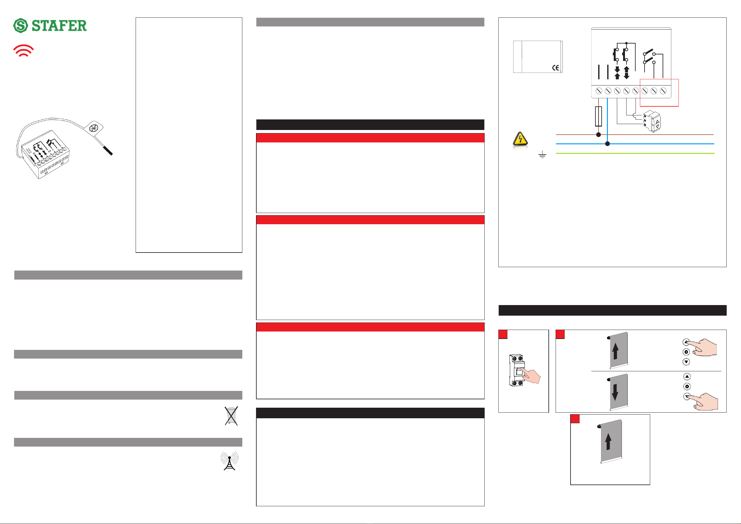
02. ELECTRICAL CONNECTION
üMake the connections with the power switched off.
üCheck that the power line does not come from electrical circuits intended for lighting.
üA circuit breaker or residual current device must be inserted in the power line. An isolating device with
overvoltage category III, namely distance between contacts of at least 3.5 mm, must be inserted in the
power line
üThe product has no protection against overloads or short circuits. Install a protective device in the
power line that is appropriate for the load, such as a fuse of max. 500mA.
üYou can not connect more than one motor directly to the module.
üUse momentary (hold-to-run) control buttons. Do NOT use stay-put switches. The control buttons are
connected to the line voltage and must therefore be properly isolated and protected.
Power supply
The module can be powered from 120Vac to 230Vac. The supply voltage must be applied to terminals 1
and 2.
Connecting the motor
The module MIR DRY can't be connected directly to the load (eg. an electric motor) as it doesn't provide
any output voltage. You must connect it to another device via the clamps 6, 7 and 8 which are dry contact,
with the common in clamp 6.
Connecting the command buttons (optional)
The buttons must be connected to terminals 3 and 4, the common thread of the buttons must be
connected to terminal 5. The command buttons are subjected to the mains voltage and therefore
must be properly insulated and protected. You must use momentary (hold-to-run) command
buttons, do not use buttons with maintained position. More than one command button can be connected
to the unit through a parallel connection. To make an up or down movement, press the button for at least
0.5 seconds; to stop the operation briefly press any of the buttons.
ü Incorrect installation can cause serious injuries.
ü Keep these instructions for future maintenance work and disposal of the product.
ü All the product installation, connection, programming and maintenance operations must be carried out
only by a qualified and skilled technician, who must comply with laws, provisions, local regulations and
the instructions given in this manual.
ü The wiring must comply with current IEC standards.
ü Some applications require hold-to-run operation and can exclude the use of radio controls or require
particular safety devices.
ü To prevent potentially dangerous situations, check the operating condition of the roller shutter/awning
regularly.
01A. WARNING FOR SAFETY
01. WARNINGS!
01. Warnings
02. Electrical connection
03. First installation
04. Memorization\deletion of a radio device
05. Operating logic of wind sensor
06. Operating logic of sun sensor
07. Operating logic of rain sensor
08. Working time
09. Orientation function
10. «Air Change» function
11. RESET
Index
Notes on radio systems
594.R.EN.00
C
CP
L N
120-230V
50-60Hz
1 2 3 4 5 6 7 8
Dry contacts
WARNING:
the figures used in the following paragraphs are generically referred to a motor
that moves a roller blind. Depending on the load applied to the module, the terms
UP and DOWN can have different meanings
(eg. LEFT and RIGHT or OPEN and CLOSE).
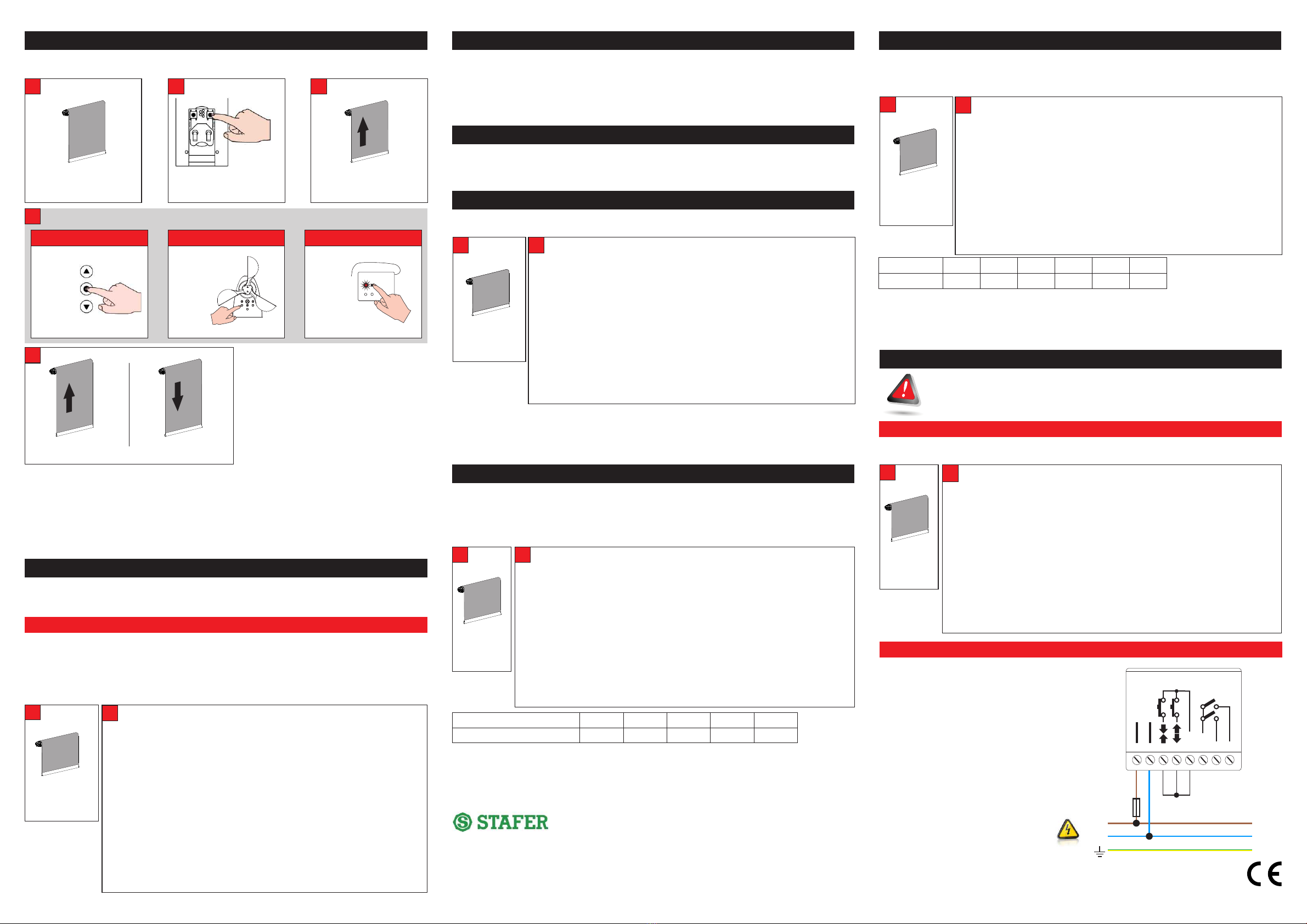
This procedure is used to memorize the first transmitter.
03. FIRST INSTALLATION
NOTE:
In the event that the installation is not successful, you can restore your system to factory condition (see
section 11. RESET).
ON
Supply the module
A
The motor
makes 4
movements...
B
C
within 15s press
x4
within 15s press
The motor makes a brief upward
movement
IF
IF x4
UP
DOWN
x1
594.R.EN.00
594.R.EN.00
L
N
MAIN
POWER SUPPLY
FUSE
500mA
C
CP
L N
120-230V
50-60Hz
1 2 3 4 5 6 7 8
DRY
11. RESET
üSwitch off power supply to the module
üConnect as show in figure
üSwitch ON power supply and wait 30 seconds until the
motor makes 2 alternating movements, to indicate that
factory conditions are restored.
üSwitch off power supply to the module
üRestore the connections (see section 02. ELECTRICAL
CONNECTIONS)
üFollow the instruction at section 03. FIRST
INSTALLATION
11B. RESET USING THE BUTTON INPUT
With this procedure you can store / delete others transmitters in addition to the first already stored, or store
/ delete wind sensor or a sun/wind sensor or store / delete a rain sensor.
NOTES:
üThe module can store up to 15 radio codes (excluding sensors, wind or sun / wind radio). The "out of
memory" condition is indicated with two downward movements.
üIf the motor has stored a single hand-held transmitter, it can't be deleted (the non-cancellation is
indicated by two downward movements).
üThe module can store up to 4 wind radio sensor, one of which may be a sun sensor / wind. The "out
of memory" condition is indicated with two downward movements.
üThe module can store more rain sensors.
(1) If the sensor is a battery sensor button 1 must be pressed up to 10 seconds.
Bring the motor to an
intermediate position
A
The motor signals the operation performed
MEMORIZED ! DELETED !
E
Press for 5 seconds the
PROG button of a transmitter
already memorized.
B
The motor makes 2 upward
movements
C
WIND SENSOR
(1)
RAIN SENSOR
P2
(1)
(1)
Hand-held TRANSMITTER
DWITHIN 15 SECONDS PRESS:
(1)
STOP P1 P2
x2
x1 x1
04. MEMORIZATION / DELETION OF A RADIO DEVICE
If a wind radio sensor measures that the wind speed is above the threshold set on the sensor, the wind
sensor sends the message of "wind alarm": the modules tuned to it makes an upward manoeuvre and
commands are inhibited as long as it remains the dangerous situation.
As soon as in the module is stored a wind sensor is automatically activated control of communication
between the wind sensor and the module. If communication is lost for more than 60 minutes, the module
performs an upward movement for the protection of the roller. This manoeuvre is performed automatically
every 60 minutes until the restoration of radio communication. The factory recommends keeping the
"radio test" in order to identify in good time any malfunction of the radio sensor. With the following
procedure you can enable or disable the "radio test":
05. OPERATING LOGIC OF WIND SENSOR
05.1 TEST RADIO FUNCTION
If the sun sensor measures a brightness above the threshold set for at least 2.5 minutes, sends the
message "sun" and modules, tuned to it, command a downward movement. If the sun sensor measures a
brightness below the threshold set for at least 18 minutes, sends the message of "no sun" and modules
594REN00, tuned to it, command an upward movement.
The "sun function" can be activated / deactivated from the transmitter (see transmitter manual under "sun
function"). If the "sun function" is deactive, 594REN00 ignores the commands about the sun sent from the
radio sensor.
06. OPERATING LOGIC OF SUN SENSOR
If the rain sensor measures a rain intensity exceeds the threshold set on the sensor, the rain sensor sends
the message "rain" and modules 594REN00, tuned to it, performs an upward or downward manoeuvre,
according to how is set the rain sensor. The manual controls are still active. More rain sensors can be
stored in the same 594REN00.
07. OPERATING LOGIC OF RAIN SENSOR
Is the closure time of the relays when a manoeuvre is commanded . The factory sets the "working time" to
120 sec.
08. WORKING TIME
NOTES:
Motor signals the current «working time».
Example: if «working time» is 120 s, motor signal is:
1 briefly movement = 1 Pause - 2 briefly movements= 2 Pause - 1 large movement = 0
If you try to set «Working time» lower than 5s or greater than 240s, the value is rejected and the motor
makes 2 short movements down
N° of movements
Duration of orientation movement
1
inactive
2
50 msec
3
100 msec
4
150 msec
5
200 msec
This feature can be useful, for example in the handling of sun protection. If the function is activated, the
RIGHT and LEFT function of the 594 transmitters will command short movements which will allow easy
orientation of the sun protection. With 593 trasmitter you must press briefly twice STOP than press UP or
DOWN. The command can also be given by any buttons connected to the module; to use the function,
press a button (less than 0.5 sec), then press it again and hold it until you reach the desired orientation.
The factory sets the function to inactive.
09. ORIENTATION FUNCTION
NOTE:
üIf you try to set «Orientation time» greater than level 5, the value is rejected and the motor makes 2
short movements down.
üIf you want to stop the procedure, press briefly the MENU button of transmitter.
üWhen «Orientation time» is set on level 1 (inactive), if you command the orientation movements by
transmitter or by command buttons, the motor will not move.
N° of movements
AIR CHANGE
1
inactive
2
2 sec
3
3 sec
4
4 sec
5
5 sec
6
6 sec
This feature is especially useful if you want to identify a preferred position of the roller blind. Recalling the
intermediate limit switch function by a stored portable transmitter, a complete operation of descent is
carried out and, elapsed the work time, an upward movement is carried out whose duration can be set via
this parameter.
10. “AIR CHANGE“ FUNCTION
NOTES:
üIf you try to set «Air change» greater than level 6, the value is rejected and the motor makes 2 short
movements down.
üWhen «Air change» is set on level 1 (inactive), if you recall the intermediate limit switch by transmitter,
the motor will not move.
11A. RESET USING A MEMORIZED TRANSMITTER
This procedure restores the receiver to the default conditions (factory settings). This
procedure must only be carried out by qualified technical staff. Having carried out the reset
procedure, the qualified technician must promptly carry out all the installation operations
described at section 03. FIRST INSTALLATION
üSelect, on the transmitter, the radio channel that controls the device you want to reset.
üMake sure that this radio channel controls only the device you want to reset.
594.R.EN.00
recycled paper versione 1.0
All products and technical specifications given in this document are subject to variation without notice. Unless previously
and specifically authorised by STAFER, the device must be used exclusively with transmitters produced by STAFER.
STAFER cannot be consider responsible for damage caused by improper, incorrect or unreasonable uses.
STAFER shall not be liable for damage resulting from improper, incorrect or unreasonable use.
STAFER S.p.a. - via Malpighi, 9 - 48018 Faenza (RA) ITALY
Tel. (+39) 0546.624811 - Fax. (+39) 0546.623141
Bring the motor
to an
intermediate
position
A
B
Only available with sensor 593KXS00, 593KXB00.
In the case of 10 channels trasmitter select the correct radio channel.
01. Bring the motor on the intermediate position.
02 By trasm. 594: press MENU for about 5 seconds; rS appears on the display
By trasm. 593: while press STOP also press PROG for about 1 sec., until the LED
lights up.
03. By trasm. 594: press one time PREV and 7 times NEXT. 17 appears on the
display.
By trasm. 593: press once UP and 7 times DOWN.
04. Press one time STOP. The receiver signals the current value.
Function active: p 1 (1 short upward movement)
Function not active: q 1 (1 short downward motion)
05. By trasm. 594: press PREV to disable the function (Of appears on the
display) or NEXT to enable the function (On appears on the display).
By trasm. 593: press DOWN to disable the function or UP to enable the function.
06. Press one time STOP. The receiver signal the new value.
Function active: p 1 - Function not active: q 1
A BB
Bring the motor
to an
intermediate
position
01. Bring the motor on the intermediate position.
02 By trasm. 594: press MENU for about 5 seconds; rS appears on the display
By trasm. 593: while press STOP also press PROG for about 1 sec., until the LED
lights up.
03. By trasm. 594: press 7 times NEXT. 07 appears on the display.
By trasm. 593: 7 times DOWN.
04. Press 1 time STOP. The receiver signals the current value. Example:
if it gets up for sec. = 2: p 2 ( 2 short upward movements)
if it gets up for sec. = 35: p 3 - pause - p 5
if it gets up for sec. = 120: p 1 pause p 2 pause p 1long
05. Using PREV/DOWN and NEXT/UP to set the new value:
for time = 3: 0 time PREV/DOWN and 3 times NEXT/UP
for time = 15: 1 time PREV/DOWN and 5 times NEXT/UP
(must be between 5 and 240)
06. Press one time STOP. The receiver signal the new value.
In the case of 10 channels trasmitter select the correct radio channel.
B
Bring motor
to an
intermediate
position
A
01. Bring the motor on the intermediate position.
02. By trasm. 594: press MENU for about 5 seconds. rS appears on the display
By trasm. 593: while press STOP also press PROG for about 1 sec., until the
LED lights up.
03. By trasm. 594: press 1 time PREV and 2 times NEXT. 12 appears on the display
By trasm. 593: press 1 time UP and 2 times DOWN.
04. Press 1 time STOP. The receiver signals the current value.
Example: if the parameter value = 4: p 4 (4 short upward movements)
05. By trasm. 594: using PREV and NEXT to set the new value (from 1 to 5.
1 is inactive. Factory set 1).
Example: for parameter = 4: (0 time PREV) - 4 times NEXT
By trasm. 593: press DOWN the number of times equal to the desired setting
(from 1 to 5. 1 is inactive. Factory set 1).
06. Press 1 time STOP. The receiver signal the new value.
In the case of 10 channels trasmitter select the correct radio channel.
A
BB
Bring motor
to an
intermediate
position
01. Bring the motor on the intermediate position.
02. By trasm. 594: press MENU for about 5 seconds. rS appears on the display.
By trasm. 593: while press STOP also press PROG for about 1 sec., until the LED
lights up.
03. By trasm. 594: press 8 times NEXT. 08 appears on the display.
By trasm. 593: 8 times DOWN.
04. Press one time STOP. The receiver signals the current value. Example:
if time = 2 sec: p 2 (2 short upward movements)
if time = 5 sec: p 5 (5 short upward movements)
05. By trasm. 594: using PREV and NEXT to set the new value:
for time 3 sec: 0 times PREV and 3 times NEXT
By trasm. 593: press DOWN the number of times equal to the desired setting.
06. Press 1 time STOP. The receiver signal the new value.
In the case of 10 channels trasmitter select the correct radio channel.
BB
In the case of 10 channels trasmitter select the correct radio channel to be resetted.
01. Bring the motor on the intermediate position.
02. By trasm. 594: press MENU for around 5 seconds. rS appears on the display.
By trasm. 593: while press STOP also press PROG for about 1 sec., until
the LED lights up.
03. By trasm. 594: press 2 times PREV and 9 times NEXT. 29 appears on the display
By trasm. 593: press 2 times UP and 9 times DOWN.
04. Press 1 time STOP. The receiver signals that it is ready for the memory reset
(with visual or acoustic signals, see the receiver instruction manual); on the
transmitter, all the leds and display segments come on intermittently for a few
seconds.
05. By trasm. 594: press together PREV and NEXT
By trasm. 593: for about 2 secondspress together UP and DOWN
The receiver signals that the factory settings have been restored (1 moviment up
and down).
06. Follow the instruction manual of the receiver to re-install the receiver.
Bring motor
to an
intermediate
position
A


