Stafix B6 User manual

®
B6/B12/B18
Instruction Manual
innovation
technology
performance
power
TM
CYCLIC WAVE
BATTERY POWERED ENERGISER
POWERS UP TO 180km/110 miles
™
CYCLIC WAVE
AUTO
BATTERY POWERED ENERGISER
POWERS UP TO 120km/80 miles
™
CYCLIC WAVE
AUTO
AUTO
™
CYCLIC WAVE
BATTERY POWERED ENERGISER
POWERS UP TO 60km/40 miles
66
BB

Contents
ENGLISH.................................................................. 1
Electric Fencing and your Stafix Energiser.............................. 1
Installation............................................................................ 1
Operation............................................................................. 3
Battery Selection and Management ...................................... 4
Building a Permanent Electric Fence...................................... 6
Temporary Electric Fencing ................................................... 8
Safety Considerations ........................................................... 8
Frequently Asked Questions/Troubleshooting...................... 12
Servicing............................................................................. 12
Product Specifications......................................................... 12
ESPAÑOL ............................................................... 13
Cercas eléctricas y su energizador Stafix .............................. 13
Instalación .......................................................................... 13
Operación........................................................................... 15
Selección y manejo de la batería ......................................... 16
Construcción de una cerca eléctrica fija............................... 18
Cercas eléctricas móviles ..................................................... 21
Instrucciones de seguridad.................................................. 21
Preguntas frecuentes y solución de problemas .................... 25
Reparaciones ...................................................................... 25
PORTUGUÊS........................................................... 26
Cercas elétricas e o seu energizador Stafix........................... 26
Instalação ........................................................................... 26
Operação............................................................................ 29
Seleção e uso da bateria ..................................................... 29
Montagem de uma cerca elétrica permanente .................... 31
Cercas elétricas temporárias................................................ 34
Instruções de segurança ..................................................... 34
Perguntas freqüentes/Solução de problemas ....................... 38
Manutenção ....................................................................... 38
FRANÇAIS.............................................................. 39
Clôtures électriques et votre électrificateur Stafix................. 39
Installation.......................................................................... 39
Utilisation ........................................................................... 41
Sélection et maniement de la batterie ................................. 42
Mise en place d’une clôture électrique permanente............. 44
Clôture électrique temporaire.............................................. 47
Règles de sécurité ............................................................... 47
Questions fréquemment posées/Problèmes et solutions ...... 51
Réparation.......................................................................... 51
Spécifications du Produit .................................................... 52
SVENSKA ............................................................... 53
Elstängsel och ditt Stafix-aggregat ...................................... 53
Installation.......................................................................... 53
Användning........................................................................ 55
Batteriets val och skötsel ..................................................... 56
Att bygga ett permanent elstängsel .................................... 58
Temporära elstängsel.......................................................... 60
Säkerhetsåtgärder............................................................... 60
Vanliga frågor/Felsökning ................................................... 63
Service................................................................................ 64
© Tru-Test Limited, 2004. All rights reserved.
Stafix is a trademark of Tru-Test Corporation Limited.
No part of this publication may be photocopied, reproduced,
stored in a retrieval system, or transmitted in any form or by any
means, electronic, mechanical, photocopying, recording or
otherwise without the prior written permission of Tru-Test
Limited. Product specifications may change without prior notice.
For more information about the Stafix range of quality products,
see www.stafix.com.
Tru-Test Limited Postal address:
25 Carbine Road P O Box 51078
Mt Wellington Pakuranga
Auckland 1006 Auckland 1730
New Zealand New Zealand
XED00051 Issue 1 02/04
ENGLISH
Electric Fencing and your Stafix
Energiser
Congratulations on your purchase of a Stafix battery
energiser. This product has been constructed using
the latest technology and construction techniques. It
has been engineered to give superior performance
and many years of service.
It is important to carefully and thoroughly read these
instructions. They contain important safety
information and will assist you in ensuring that your
electric fencing system gives maximum performance
and reliability.
Explanation of symbols that may be on your
energiser
1
Indicates that, to reduce the risk of
electric shock, the energiser should be
opened or repaired only by qualified
Stafix-appointed personnel.
Read full instructions before use.
How does an electric fence work?
An electric fence system comprises an energiser and
an insulated fence. The energiser puts very short
pulses of electricity onto the fence line. These pulses
have a high voltage, but are of very short duration
(less than 3/10,000ths of a second). However, a shock
from an electric fence pulse is very uncomfortable and
animals quickly learn to respect electric fences. An
electric fence is not only a physical barrier, but is also
a strong psychological barrier.
What are the benefits of an electric fence?
An electric fence has many benefits over conventional
fencing:
Requires less labour and material to construct
than conventional fencing.
•
•
•
•
•
•
•
Flexibility to change or add paddocks when
required. The use of strip grazing techniques can
allow temporary fencing to be quickly and easily
erected or removed.
Controls a broader range of animals.
Minimises damage to expensive livestock when
compared with other fencing mechanisms, for
example barbed wire.
Installation
Read all of the safety instructions in this manual
carefully before installing the battery energiser. There
are three types of installation:
Battery-only installation
Solar installation
Battery maintained installation
Battery-only installation
2
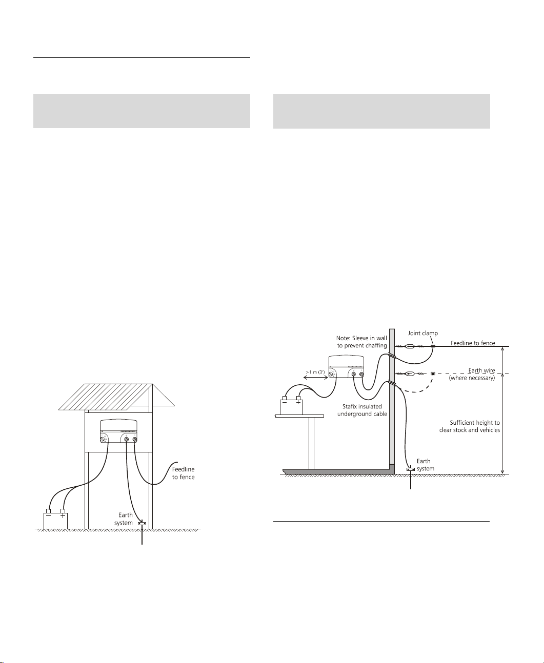
Installing the energiser outside
Warning! Before installing the energiser, ensure
the energiser is switched off.
1 Select a suitable site for the energiser.
Ensure that the energiser is protected from
animals and the environment. If necessary, house
the energiser in a protective box. Consider site
access, proximity to a suitable area for earthing
and whether the energiser is safe from human
interference. Try to position the energiser as near
as possible to the centre of the electric fence. To
avoid possible damage to the energiser, ensure
that the battery is at least 1 m (3’) away from
and not directly below the energiser.
2 Mount the energiser on a post. Use the template
printed inside the back cover of this manual.
3 Connect the energiser fence Earth terminal
(green) to the earthing system.
4 Connect the energiser Fence output terminal
(red) to the fence.
5 Attach the red (+) energiser clip to the positive
terminal of the battery, and the black (–) clip to
its negative terminal. For permanent installations,
use wire to connect the energiser to the battery.
Installing the energiser inside
Warning! Before installing the energiser, ensure
the energiser is switched off.
1 Select a suitable place for the energiser.
Ensure that the energiser and battery are out of
reach of children. The battery must be level. To
avoid possible damage to the energiser, ensure
that the battery is at least 1 m (3’) away from
and not directly below the energiser.
2 Mount the energiser on a wall. Use the template
printed inside the back cover of this manual.
3 Connect the energiser fence Earth terminal
(green) to the earthing system.
4 Connect the energiser Fence output terminal
(red) to the fence.
5 Attach the red (+) energiser clip to the positive
terminal of the battery, and the black (–) clip to
its negative terminal. For permanent installations,
use wire to connect the energiser to the battery.
Solar installation
Solar panel selection, assembly and positioning
Refer to the “Stafix Solar Selection Guide” for
information about selecting components, assembling
and positioning a solar energiser system.

Battery maintained installation
3
This energiser has been designed to operate safely
with a battery charger power pack.
A battery maintained installation allows the energiser
to draw its normal operating power through a battery
charger power pack connected to a mains/line power
source. This enables the energiser to continue
operating from a battery supply during a power
outage. A battery maintained installation is normally
indoors.
A battery maintained installation is recommended
where stock control is critical, for example for
controlling game, high value stock, diseased stock or
where a fence line borders a public highway. A
suitable battery charger power pack can be purchased
from your nearest Stafix stockist.
Warning! A rechargeable 12 V, lead-acid battery
must be used with a battery maintained installation.
Installing the energiser with a battery charger power pack
Warning! Before installing the energiser, ensure
the energiser is switched off.
1 Select a suitable place indoors for the energiser
and battery charger power pack.
Ensure that the energiser, battery and battery
charger power pack are out of reach of children.
The battery charger power pack should be
mounted close to a power outlet. The battery
must be level. To avoid possible damage to the
energiser ensure that the battery is at least 1 m
(3’) away from and not directly below the
energiser.
Warning! Ensure there is adequate ventilation
to allow gases to disperse from the battery.
2 Mount the energiser on a wall. Use the template
printed inside the back cover of this manual.
3 Connect the energiser fence Earth terminal
(green) to the earthing system.
4 Connect the energiser Fence output terminal
(red) to the fence.
5 Attach the red (+) energiser clip to the positive
terminal of the battery, and the black (–) clip to
its negative terminal. For permanent installations,
use wire to connect the energiser to the battery.
6 Connect the battery to the battery charger power
pack.
7 Connect the battery charger power pack to the
mains/line power.
Operation
Keep this manual in a handy location.•
•
•
Carefully read all the safety considerations in this
manual. See Safety Considerations on page 8.
Carefully check your installation to ensure that it
complies with all local safety regulations.
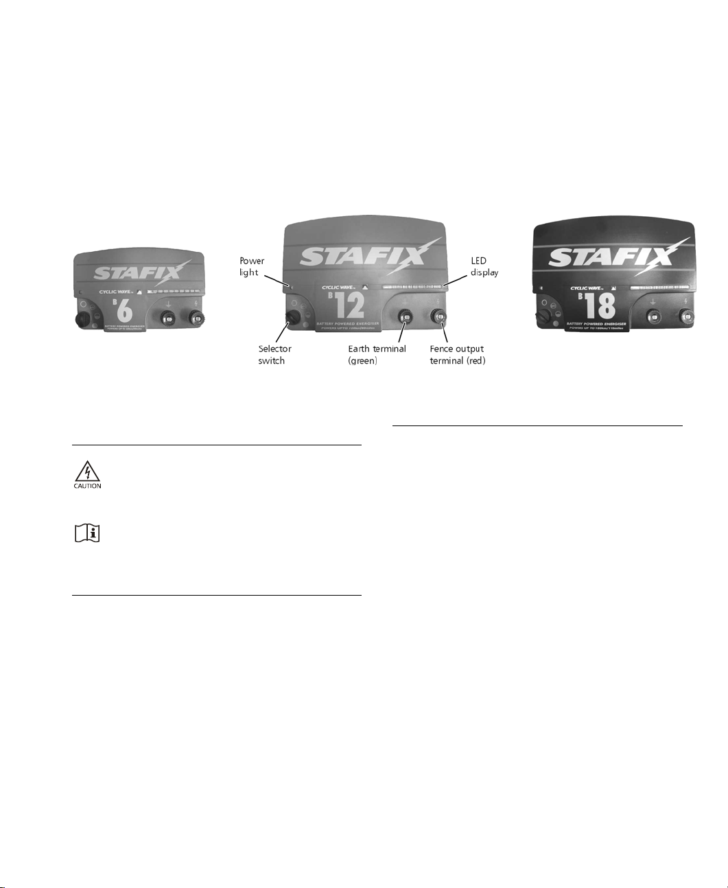
1 Ensure the Selector switch is set to Off. The
Power light is illuminated when the energiser is
receiving power.
2 Select the output setting using the Selector
switch. See Selector Switch on page 3.
The LED display indicates the output voltage of
the energiser. See LED display on page 4.
Selector Switch
The energiser functions according to the position of
the Selector switch. The Selector switch controls the
power output setting of the energiser.
Setting Description
Off Turns the energiser off. Keep the energiser off
while setting up your fence line to avoid
accidental shock.
Auto The energiser automatically adjusts power output
as the fence load increases or decreases.
Half Overrides the automatic adjustment and keeps
the energiser in reduced-power mode
permanently.
Full Overrides the automatic adjustment and keeps
the energiser in full-power mode permanently.

4
LED display
You can use the LED display to read voltage at the output terminals of the energiser.
Reading voltage
When the energiser pulses, each of the first nine segments on the LED display represents an increment of
approximately 1 kV (1000 V) of output voltage. For example, if the first four segments are illuminated at each
pulse, the output voltage is approximately 4 kV (4000 V).
If you see only red lights at each pulse and no green lights, this means that your fence line is very heavily loaded,
and you need to look for faults on the fence line.
The tenth segment of the LED display illuminates when the energiser is delivering full power.
Battery Selection and Management
This section refers exclusively to re-chargeable, lead-acid batteries, for example car, tractor, truck, marine or
specialist deep-cycle batteries.
The battery you select will depend on whether your installation is a battery-only, battery maintained or a solar
installation. For all three types of installation, the position of the energiser Selector switch will determine the size of
battery required. Refer to Operation on page 3 for an explanation of the function of the Selector switch.
Battery selection for a battery-only installation
As a guide, the amp hour (Ah) rating of the 12 V lead-acid battery required for each model is shown below. This
table is based on a seven day operating period between battery charging. Although operating time can exceed
seven days, this is likely to cause battery damage and will necessitate frequent replacement of the battery. For best
system reliability and long term battery life, the preferred battery and charging regime is to use a deep-cycle, lead-
acid battery and to recharge it when it has discharged to 50% charge level.
Energiser Selector Switch Positions Current Required Battery Capacity (90% Discharge)
B6 Full Power
Half Power
0.85 A
0.35 A
150 Ah
65 Ah
B12 Full Power
Half Power
1.7 A
0.75 A
320 Ah
140 Ah
B18 Full Power
Half Power
2.1 A
1.1 A
400 Ah
210 Ah
Battery selection for a solar installation
The battery and solar panel must be selected carefully to suit the energiser’s electrical current consumption. This
will depend on the position of the energiser Selector switch, the energiser model being used and the amount of
sunshine at the location of the installation.
As a guide, the minimum amp hour (Ah) rating of the 12 V lead-acid battery required for each model is shown
below. This table is based on average usage over seven days with no sunlight. It takes into account the variety of
solar panel and regulator types that could be used in a solar installation. For more detailed information, refer to
the “Stafix Solar Selection Guide”.
5
Energiser Model
Selector Switch Position
Current Required
Recommended Battery Capacity
(50% Discharge)
B6 Full Power
Half Power
0.85 A
0.35 A
270 Ah
120 Ah
B12 Full Power
Half Power
1.7 A
0.75 A
600 Ah
250 Ah
B18 Full Power
Half Power
2.1 A
1.1 A
700 Ah
370 Ah
Battery selection for a battery maintained installation
Warning! A rechargeable 12 V lead-acid battery must be used for a battery maintained installation.
The battery selected for a battery maintained installation must be able to supply the energiser’s current
requirements for the duration of a mains/power outage. For maximum reliability, the battery should not be
discharged below a 50% charge level. The table below is based on a 12 hour power outage.
The battery charger power pack should be able to supply the energiser’s current requirements and recharge the
battery in an acceptable time. The recharge times shown in the table are for the Stafix 2 A (FSTPP2A) and 4 A
(FSTPP4A) battery charger power packs.
Energiser
Model
Selector Switch
Position
Current
Required
Minimum Battery
Capacity
Recharging Time
(after 12 hours)
Battery Charger
Power Pack
B6 Full Power
Half Power
0.85 A
0.35 A
20 Ah
9 Ah
11 hours
4 hours
2 A
B12 Full Power
Half Power
1.7 A
0.75 A
41 Ah
18 Ah
12 hours
4 hours
4 A
B18 Full Power
Half Power
2.1 A
1.1 A
51 Ah
27 Ah
17 hours
6 hours
4 A
Battery management
Battery charging
A battery-only installation has unique requirements.
Regular recharging of the battery is essential. Use a
suitably-rated battery charger to recharge the battery.
Refer to the battery manufacturer’s
recommendations.
1 Disconnect the battery from the energiser.
2 Attach the positive (+) battery charger lead to
the positive terminal of the battery, and the
negative (–) battery charger lead to the negative
terminal on the battery.
3 Plug the battery charger into the mains/line
power supply socket and turn the power on.
4 After the battery is charged, disconnect it from
the battery charger before connecting it to the
energiser.
Caution! Over-charging the battery will reduce its
life. Do not exceed the recommendations of the
battery manufacturer when recharging the battery.
Correctly installed solar energiser systems and battery
maintained installations require very little battery
maintenance. The solar panel or battery charger
power pack should be sufficient to maintain the
battery at full or near-full charge.
Warning! Batteries contain harmful chemicals and
when used incorrectly, may cause injury. Observe
the guidelines for battery care, maintenance and
safety in this manual and in the documentation
supplied with your battery.

Battery care and maintenance
House the battery in a suitably designed battery
box, if the battery is likely to be exposed to the
weather.
6
•
•
•
•
•
•
•
•
•
When not in use, keep the battery as fully
charged as possible.
Recharge a discharged battery as soon as
possible.
Batteries should be stored fully charged and
recharged at regular intervals (every 8 weeks)
Inspect the battery regularly to ensure that the
electrolyte level does not fall below 12 mm (½”)
above the surface of the battery plates.
Fill using deionised, distilled or rain water. Do not
overfill. Refer to the battery manufacturer’s
recommendations for more information.
Battery safety
Ensure that the battery is well ventilated when
recharging.
Avoid temperatures greater than 50 °C (120 °F).
Ensure the battery is not exposed to naked flame
or sparks.
Building a Permanent Electric
Fence
Components of an electric fence
An electric fence system comprises the following
elements:
•
•
•
•
An energiser.
An earth system. This comprises a number of
metal rods inserted into the ground, which are
connected to the Earth terminal on the energiser.
Stafix insulated underground cables. Used to
connect the energiser to the earth and fence.
An insulated fence. Connected to the Fence
terminal of the energiser. Fences can be made to
a variety of designs (see below).
Note: The animal receives a shock when it completes
a circuit between the fence and the earth system. The
fence below has all live wires and requires conductive
soils. These fences are often referred to as ‘all-live’ or
‘earth-return’ fences.
Other useful components that can be added:
Cut-out switches. Installed at regular
intervals, these allow you to isolate
sections of the fence for repair.
Lightning diverter kit. Used to minimise
the damage to your energiser from
lightning conducted down the fence line.
Alternative installation
For poor conductivity soils (dry or sandy), a ‘fence-
return’ or ‘earth-wire-return’ system is recommended.
On these fences the Earth terminal is connected
directly to at least one of the fence wires. The animal
gets maximum shock from touching a live and earth
wire at the same time.
Fence designs
Fences can be constructed to suit the type of livestock
and materials available. Discuss with your Stafix
distributor which design best suits your needs. Some
suggested fence configurations are below.
Cattle and horses
10-15 m (33-49’) spacing, posts only

15-20 m (49-65’) spacing with droppers
Sheep, goats, cattle and horses
10 m (33’) spacing, posts only
15 m (49’) spacing with droppers
Wild animals
7 wire, 10 m (33’) spacing with droppers
End assemblies
7
Angle stay
Suitable for field gate, high-tension strainer.
After firmly setting the footed strainer in the ground,
dig in the stay block just below ground level, at a
distance to ensure the angle stay will be held snugly
in position. The stay can be levered into position with
a spade.
All-live system
Earth-return system
Horizontal stay
Suitable for field gate, high-tension strainer.
Very simple to erect and most suitable as a high
tension strainer, excellent in areas where the soil gets
very wet or where heavy frost occurs.
Installing and testing an earth system
Select a suitable site for the earth system. Sites need
to be:
At least 10 m (33’) from other earth systems (e.g.
telephone, mains power or the earth system from
another energiser).
•
• Away from stock or other traffic that could
interfere with the installation.

At a site that can be easily observed for
maintenance.
8
•
• Ideally at a site that has damp soil (e.g. a shaded
or swampy location). Note that the earth does
not need to be directly adjacent to the energiser
installation.
Drive Stafix earth rods into the ground. Use high-
voltage, insulated cable and earth clamps to
continuously connect the earth rods and the
energiser’s Earth terminal. Make sure the insulation is
stripped back to ensure good contact between the
wire and the earth rod.
The number of earth rods used will vary with the soil
conditions. For larger energisers, at least six 2 m
(6’6”) earth rods are required. To ensure that an
adequate number of earth rods have been used, test
the earth system using the following procedure:
1 Turn off the energiser.
2 At least 100 m (330’) away from the energiser,
short circuit the fence by laying several steel rods
or lengths of pipe against the fence. For best
results, the fence voltage should be lowered to
2000 V or less. In dry or sandy conditions, it may
be necessary to drive the rods up to 300 mm (1’)
into the earth.
Note: It is not acceptable to short circuit a fence
return system to the earth wire of the fence.
3 Turn the energiser back on.
4 Using a Stafix Digital Voltmeter, ensure that the
fence voltage is below 2 kV.
5 Check your earth system. Insert the voltmeter’s
earth probe into the ground at the full extent of
the lead, and hold the hook against the last earth
rod. The tester should not read more than
0.3 kV. Anything higher than this indicates that
better earthing is required. Either add more earth
rods or find a better ground area to drive in the
earth rods.
Note: When earthing energisers located in dairies,
earth at least 20 m (65’) away from the dairy using
double insulated wire to avoid touching the dairy
building or equipment.
Temporary Electric Fencing
Stafix offers a range of products that allow the farmer
to construct a temporary electric fence. A temporary
fence that can be quickly erected and easily moved
allows the farmer to:
Make smaller paddocks (fields)•
•
•
Keep herds of animals separated
Ration feed
Note: Use more wires for smaller animals and wild
animals. Politape should be used when greater
visibility is required (e.g. horses).
An example of a temporary fence is shown below.
Safety Considerations
Definition of special terms
Electric fence energiser – An appliance that is
intended to periodically deliver voltage impulses to a
fence connected to it.
Fence – A barrier for animals or for the purpose of
security, comprising one or more conductors such as
metal wires, rods or rails.
Electric fence – A barrier which includes one or more
electric conductors, insulated from earth, to which
electric pulses are applied by an energiser.
Fence circuit – All conductive parts or components
within an energiser that are connected or are
intended to be connected, galvanically, to the output
terminals.
Earth electrode – Metal structure that is driven into
the ground near an energiser and connected
electrically to the output Earth terminal of the

9
energiser, and that is independent of other earthing
arrangements.
Connecting lead – An electric conductor, used to
connect the energiser to the electric fence or the earth
electrode.
Electric animal fence – An electric fence used to
contain animals within or exclude animals from a
particular area.
Electric security fence – A fence used for security
purposes which comprises an electric fence and a
physical barrier electrically isolated from the electric
fence.
Physical barrier – A barrier not less than 1.5 m (5’)
high intended to prevent inadvertent contact with the
pulsed conductors of the electric fence. Physical
barriers are typically constructed from vertical
sheeting, rigid vertical bars, rigid mesh, rods or
chainwire mesh.
Public access area – Any area where persons are
protected from inadvertent contact with pulsed
conductors by a physical barrier.
Pulsed conductors – Conductors which are subjected
to high voltage pulses by the energiser.
Secure area – The side of an electric security fence
where a person may come into contact with the
electric fence, without the protection of a physical
barrier.
Requirements for electric animal fences
Electric animal fences and their ancillary equipment
shall be installed, operated and maintained in a
manner that minimises danger to persons, animals or
their surroundings.
Electric animal fence constructions that are likely to
lead to the entanglement of animals or persons shall
be avoided.
An electric animal fence shall not be supplied from
two separate energisers or from independent fence
circuits of the same energiser.
For any two separate electric animal fences, each
supplied from a separate energiser independently
timed, the distance between the wires of the two
electric animal fences shall be at least 2 m (6’6”). If
this gap is to be closed, this shall be effected by
means of electrically non-conductive material or an
isolated metal barrier.
Barbed wire or razor wire shall not be electrified by an
energiser.
A non-electrified fence incorporating barbed wire or
razor wire may be used to support one or more offset
electrified wires of an electric animal fence. The
supporting devices for the electrified wires shall be
constructed so as to ensure that these wires are
positioned at a minimum distance of 150 mm (6”)
from the vertical plane of the non-electrified wires.
The barbed wire and razor wire shall be earthed at
regular intervals.
Follow our recommendations regarding earthing. See
Installing and testing an earth system on page 7.
A distance of at least 10 m (33’) shall be maintained
between the energiser earth electrode and any other
earthing system connected parts such as the power
supply system protective earth or the
telecommunication system earth.
Connecting leads that are run inside buildings shall be
effectively insulated from the earthed structural parts
of the building. This may be achieved by using
insulated high voltage cable.
Connecting leads that are run underground shall be
run in conduit of insulating material or else insulated
high voltage cable shall be used. Care must be taken
to avoid damage to the connecting leads due to the
effects of animal hooves or vehicle wheels sinking into
the ground.
Connecting leads shall not be installed in the same
conduit as the mains supply wiring, communication
cables or data cables.
Connecting leads and electric animal fence wires shall
not cross above overhead power or communication
lines.
Crossings with overhead power lines shall be avoided
wherever possible. If such a crossing cannot be
avoided it shall be made underneath the power line
and as nearly as possible at right angles to it.
If connecting leads and electric animal fence wires are
installed near an overhead power line, the clearances
shall not be less than those shown in the table below.
Minimum clearances from power lines for electric
animal fences
Power line voltage Clearance
≤1000 V 3 m (10’)
>1000 ≤33,000 V 4 m (13’)
>33,000 V 8 m (27’)

If connecting leads and electric animal fence wires are
installed near an overhead power line, their height
above the ground shall not exceed 3 m (10’). This
height applies to either side of the orthogonal
projection of the outermost conductors of the power
line on the ground surface, for a distance of:
2 m (6’6”) for power lines operating at a nominal
voltage not exceeding 1000 V.
10
•
•
•
•
15 m (50’) for power lines operating at a
nominal voltage exceeding 1000 V.
Electric animal fences intended for deterring birds,
household pet containment or training animals such
as cows need only be supplied from low output
energisers to obtain satisfactory and safe
performance.
In electric animal fences intended for deterring birds
from roosting on buildings, no electric fence wire
shall be connected to the energiser earth electrode. A
warning sign shall be fitted to every point where
persons may gain ready access to the conductors.
Where an electric animal fence crosses a public
pathway, a non-electrified gate shall be incorporated
in the electric animal fence at that point or a crossing
by means of stiles shall be provided. At any such
crossing, the adjacent electrified wires shall carry
warning signs.
Any part of an electric animal fence that is installed
along a public road or pathway shall be identified at
frequent intervals by warning signs securely fastened
to the fence posts or firmly clamped to the fence
wires.
The size of the warning sign shall be at least
100x200 mm (4x8”).
The background colour of both sides of the
warning sign shall be yellow. The inscription on
the sign shall be black and shall be either:
or the substance of “CAUTION: Electric animal
fence”.
• The inscription shall be indelible, inscribed on
both sides of the warning sign and have a height
of at least 25 mm (1”).
Ensure that all mains-operated, ancillary equipment
connected to the electric animal fence circuit provides
a degree of isolation between the fence circuit and
the supply mains equivalent to that provided by the
energiser.
Protection from the weather shall be provided for the
ancillary equipment unless this equipment is certified
by the manufacturer as being suitable for use
outdoors, and is of a type with a minimum degree of
protection IPX4.
Requirements for electric security fences
Electric security fences and their ancillary equipment
shall be installed, operated and maintained in a
manner that minimises danger to persons, and
reduces the risk of persons receiving an electric shock
unless they attempt to penetrate the physical barrier,
or are in the secure area without authority.
Electric security fence constructions that are likely to
lead to the entanglement of persons shall be avoided.
Gates in electric security fences shall be capable of
being opened without the person receiving an electric
shock.
An electric security fence shall not be supplied from
two separate energisers or from independent fence
circuits of the same energiser.
For any two separate electric security fences, each
supplied from a separate energiser independently
timed, the distance between the wires of the two
electric security fences shall be at least 2.5 m (9’). If
this gap is to be closed, this shall be effected by
means of electrically non-conductive material or an
isolated metal barrier.
Barbed wire or razor wire shall not be electrified by an
energiser.
Follow our recommendations regarding earthing. See
Installing and testing an earth system on page 7.
The distance between any electric security fence earth
electrode and other earth systems shall not be less
than 2 m (6’6”), except when associated with a
graded earth mat.
Note: Where possible this distance should be at least
10 m (33’).
Exposed conductive parts of the physical barrier shall
be effectively earthed.
Where an electric security fence passes below bare
power line conductors, the highest metallic element
shall be effectively earthed for a distance of not less
than 5 m (17’) on either side of the crossing point.

Connecting leads that are run inside buildings shall be
effectively insulated from the earthed structural parts
of the building. This may be achieved by using
insulated high voltage cable.
11
•
•
•
•
•
•
•
•
Connecting leads that are run underground shall be
run in conduit of insulating material or else insulated
high voltage cable shall be used. Care must be taken
to avoid damage to the connecting leads due to the
effects of vehicle wheels sinking into the ground.
Connecting leads shall not be installed in the same
conduit as the mains supply wiring, communication
cables or data cables.
Connecting leads and electric security fence wires
shall not cross above overhead power or
communication lines.
Crossings with overhead power lines shall be avoided
wherever possible. If such a crossing cannot be
avoided it shall be made underneath the power line
and as nearly as possible at right angles to it.
If connecting leads and electric security fence wires
are installed near an overhead power line, the
clearances shall not be less than those shown in the
table on page 9.
If connecting leads and electric security fence wires
are installed near an overhead power line, their height
above the ground shall not exceed 3 m (10’). This
height applies to either side of the orthogonal
projection of the outermost conductors of the power
line on the ground surface, for a distance of:
2 m (6’6”) for power lines operating at a nominal
voltage not exceeding 1000 V.
15 m (50’) for power lines operating at a
nominal voltage exceeding 1000 V.
A spacing of 2.5 m (9’) shall be maintained between
uninsulated electric security fence conductors or
uninsulated connecting leads supplied from separate
energisers. This spacing may be less where conductors
or connecting leads are covered by insulating sleeving,
or consist of insulated cables rated to at least 10 kV.
This requirement need not apply where the separately
energized conductors are separated by a physical
barrier that does not have any openings greater than
50 mm (2”).
A vertical separation of not less than 2 m (6’6”) shall
be maintained between pulsed conductors fed from
separate energisers.
Electric security fences shall be identified by
prominently placed warning signs.
The warning signs shall be legible from the secure
area and the public access area.
Each side of the electric security fence shall have at
least one warning sign.
Warning signs shall be placed:
at each gate
at each access point
at intervals not exceeding 10 m (33’)
adjacent to each sign relating to chemical
hazards for the information of the emergency
services
Any part of an electric security fence that is installed
along a public road or pathway shall be identified at
frequent intervals by warning signs securely fastened
to the fence posts or firmly clamped to the fence
wires.
The size of the warning sign shall be at least
100×200 mm (4x8”).
The background colour of both sides of the
warning sign shall be yellow. The inscription on
the sign shall be black and shall be either:
or the substance of “CAUTION: Electric security
fence”.
The inscription shall be indelible, inscribed on
both sides of the warning sign and have a height
of at least 25 mm (1”).
•
Ensure that all mains operated, ancillary equipment
connected to the electric security fence circuit
provides a degree of isolation between the fence
circuit and the supply mains equivalent to that
provided by the energiser.
Mains supply wiring shall not be installed in the same
conduit as signalling leads associated with the electric
security fence installation.
Protection from the weather shall be provided for the
ancillary equipment unless this equipment is certified
by the manufacturer as being suitable for use
outdoors, and is of a type with a minimum degree of
protection IPX4.
Frequently Asked
Questions/Troubleshooting
What voltage is required to control animals?
4 kV is widely accepted as the recommended
minimum voltage to control animals. However, you
also require a well constructed fence system to ensure
that animals cannot push through electrified wires.
The fence voltage is below 4 kV. How do I increase the
voltage?
Check the energiser. Ensure that the energiser is not
set to operate at half power. Disconnect the
energiser from the fence and earth system. Measure
the voltage across the energiser terminals with a Stafix
Fence Compass, DVM or Lite Tester. If the voltage is
less than 6 kV, request your Stafix service agent to
check the energiser.
Check the energiser earthing. Use the procedure
described in Installing and testing an earth system on
page 7.
Check your fence system for faults. The most
common source of low voltage is faults on the fence
line.
If the fence, earth and energiser are in good condition
and the voltage is still below 4 kV, talk to your Stafix
distributor. They will help you identify whether recent
extensions to your fence, a poor fence layout, or soil
conditions may be causing inadequate voltage.
How do I locate faults?
The recommended tool for locating faults is the Stafix
Fence Compass. This combined voltage and current
meter allows you to rapidly locate sources of current
leakage. Alternatively, use a Stafix DVM or Lite Tester.
Use cut-out switches to turn off the power to
different sections of the farm. If the voltage on the
fence increases when a section of the farm is turned
off, then investigate that section for possible faults.
There are no lights flashing on the energiser.
Check the power supply. Ensure that the power is
switched on. If the energiser still does not operate,
request your Stafix service agent to check the
energiser.
There are no green lights, only red lights illuminating
on the LED display
The green lights on the LED display represent the
output voltage of the energiser. If no green lights
illuminate when the energiser pulses, there may be
faults on the fence line. See How do I locate faults?
above.
Servicing
This energiser contains no user serviceable parts. It
must be returned to a Stafix-appointed service agent
for repair. If the supply cord is damaged it must only
be replaced by a Stafix-appointed service agent, as a
special cord is required.
Product Specifications
B6 B12 B18
Power Supply
12 V
(optional solar panel)
12 V
(optional solar panel)
12 V
(optional solar panel)
Current Consumption 0.35-0.85 A 0.75-1.7 A 1.1-2.1 A
Maximum Output Voltage up to 8.5 kV up to 8.0 kV up to 8.0 kV
Output Energy at 500 Ω
(for European models) 4.6 J 4.2 J
Maximum Output Energy 6.7 J 12.0 J 18.0 J
Stored Energy 10.0 J 20. 0 J 30.0 J
Dimensions (WxHxD)
100x175x270 mm
(4x7x10½”)
350x240x115 mm
(13¾x9½x6”)
350x240x115 mm
(13¾x9½x6”)
Weight (approximate) 3.6 kg (7 lb,15 oz) 7.3 kg (16 lb,2oz) 7.8 kg (17 lb,3oz)
12

ESPAÑOL
Cercas eléctricas y su energizador
Stafix
Felicitaciones por haber adquirido un energizador o
electrificador Stafix alimentado por la red de corriente
eléctrica. Este aparato ha sido construido según la
tecnología y las técnicas de construcción más
modernas. Está diseñado para ofrecer máximo
rendimiento y una larga duración de vida.
Es importante que usted lea atentamente estas
instrucciones. Contienen informaciones importantes
relativas a la seguridad y le ayudarán a asegurar que
su sistema de cerca eléctrica brinde máximo
rendimiento y fiabilidad.
Explicación de los símbolos en el energizador
13
Indica que para disminuir el riesgo de una
descarga eléctrica, el energizador debería ser
abierto y/o reparado sólo por el personal
cualificado Stafix
Lea todas las instrucciones antes del uso
¿Cómo funciona una cerca eléctrica?
Un sistema de cerca eléctrica consta de un
energizador o electrificador y de una cerca aislada. El
energizador envía impulsos de corriente muy cortos a
la línea de la cerca. Estos impulsos están
caracterizados por un alto voltaje y una duración muy
corta (inferior a 3/10.000 de segundo). A pesar de la
corta duración, una descarga provocada por un
impulso de cerca eléctrica es muy desagradable y los
animales aprenden rápidamente a respetar las cercas
eléctricas. Una cerca eléctrica no sólo constituye una
barrera física sino una gran barrera psicológica.
¿Cuáles son las ventajas de una cerca
eléctrica?
Una cerca eléctrica tiene numerosas ventajas en
comparación con una cerca convencional.
Requiere menos trabajo y material que una cerca
convencional.
•
•
•
•
•
•
•
Ofrece la flexibilidad de hacer más o menos
divisiones cuando las necesite. Instalación o
desmontaje rápido y fácil de cercas móviles para
el pastoreo intensivo.
Permite el control de muchos tipos de animales.
Minimiza daños causados a animales bajando el
costo en comparación con otros tipos de cerca,
ej. de alambre de espino.
Instalación
Lea atentamente todas las instrucciones de seguridad
en este manual antes de instalar el energizador a
batería. Existen tres tipos de instalación:
Instalación sólo con batería
Instalación solar
Instalación apoyada por batería

Instalación sólo con batería
14
Instalar el energizador al aire libre
¡Advertencia! Antes de instalar el energizador,
asegúrese de que éste esté apagado.
1 Elija un lugar adecuado para el energizador.
Asegúrese de que el energizador esté protegido
de animales y condiciones ambientales. De ser
necesario, coloque el energizador en una caja
para batería. Procure que el lugar de instalación
sea de acceso fácil, esté cerca de un área
adecuada para la toma a tierra y esté protegido
contra daños causados por el hombre. Procure
colocar el energizador lo más cerca posible del
centro de la cerca eléctrica. Para evitar que se
dañe el energizador, asegúrese de que la batería
se encuentre a no menos de 1 m de éste y no
directamente debajo del energizador.
2 Monte el energizador en un poste. Utilice el
patrón que se encuentra en la tapa trasera de
este manual.
3 Conecte la conexión de toma a tierra de la cerca
(verde) del energizador a su sistema de toma a
tierra.
4 Conecte la conexión de salida a la cerca (rojo) del
energizador a la cerca.
5 Conecte el borne rojo (+) del energizador al
terminal positivo de la batería y el borne negro (-)
al terminal negativo de la batería. Para
instalaciones fijas, utilice alambre para conectar
el energizador a la batería.
AUTO
Sistema de
toma a tierra
Línea de
alimentaci
de la cerca
ón
Instalar el energizador en un edificio
¡Advertencia! Antes de instalar el energizador,
asegúrese de que éste esté apagado.
1 Elija un lugar adecuado para el energizador.
Asegúrese de que el energizador y la batería
estén fuera del alcance de los niños. La batería ha
de situarse en posición plana. Para evitar que se
dañe el energizador, asegúrese de que la batería
se encuentre a no menos de 1 m de éste y no
directamente debajo del energizador.
2 Monte el energizador en una pared. Utilice el
patrón que se encuentra en la tapa trasera de
este manual.
3 Conecte la conexión de toma a tierra de la cerca
(verde) del energizador a su sistema de toma a
tierra.
4 Conecte la conexión de salida a la cerca (rojo) del
energizador a la cerca.
5 Conecte el borne rojo (+) del energizador al
terminal positivo de la batería y el borne negro (-)
al terminal negativo de la batería. Para
instalaciones fijas, utilice alambre para conectar
el energizador a la batería.
Sistema de
toma a tierra
Nota: el manguito
en la pared evita el
roce de los cables Línea de alimentación
de la cerca
Alambre de toma a tierra
(donde sea necesario)
Tornillo tuerca unión
Suficiente altura para
permitir el paso del
ganado y de vehículos
Cable subterráneo
aislado Stafix
AUTO
>1 m
Instalación solar
Selección, montaje y posicionamiento del panel solar
Para informaciones relativas a la selección de
componentes, al montaje y al posicionamiento de
sistemas de energizadores con panel solar, véase la
“Stafix Solar Selection Guide” (“Guía de selección de
instalaciones solares Stafix”).

Instalación apoyada por batería
15
Este energizador ha sido concebido para que funcione
de manera segura con un transformador de
alimentación-cargador de batería.
Una instalación apoyada por batería permite al
energizador de funcionar gracias a un transformador
de alimentación-cargador de batería que está
conectado a una fuente de energía suministrando
corriente de la red. Esto permite al energizador de
seguir funcionando y de ser alimentado por la batería
en caso de una interrupción de corriente.
Normalmente esta instalación apoyada por batería se
monta en un edificio.
Se recomienda una instalación apoyada por batería en
caso de un control crítico de animales, ej. caza,
animales de mucho valor o cuando una línea de cerca
linda con una carretera pública. Un transformador de
alimentación-cargador de batería puede ser
comprado de su distribuidor local Stafix.
¡Advertencia! Con una instalación apoyada por
batería, se ha de utilizar una batería de plomo-
ácido recargable de 12 V.
Instalar el energizador con un transformador de alimentación-
cargador de batería
¡Advertencia! Antes de instalar el energizador,
asegúrese de que éste esté apagado.
1 Elija en el edificio un lugar adecuado para el
energizador y el transformador-cargador de
batería.
Asegúrese de que el energizador, la batería y el
transformador de alimentación-cargador de
batería estén fuera del alcance de los niños. El
transformador de alimentación-cargador de
batería debería ser montado cerca de un enchufe
hembra tomacorriente. La batería ha de situarse
en posición plana. Para evitar que se dañe el
energizador, asegúrese de que la batería se
encuentre a no menos de 1 m de éste y no
directamente debajo del energizador.
¡Advertencia! Asegúrese de que haya
suficiente ventilación para que no se acumulen
gases alrededor de la batería.
2 Monte el energizador en una pared. Utilice el
patrón que se encuentra en la tapa trasera de
este manual.
3 Conecte la conexión de toma a tierra de la cerca
(verde) del energizador a su sistema de toma a
tierra.
4 Conecte la conexión de salida a la cerca (rojo) del
energizador a la cerca.
5 Conecte el borne rojo (+) del energizador al
terminal positivo de la batería y el borne negro (-)
al terminal negativo de la batería. Para
instalaciones fijas, utilice alambre para conectar
el energizador a la batería.
6 Conecte la batería al transformador de
alimentación-cargador de batería.
7 Conecte el transformador de alimentación-
cargador de batería a la corriente de la red.
AUTO
Suministro de la
corriente de la red Energizador
Transformador
de
cargador
de batería
alimentación-
Hacia la cerca
y el sistema
de toma a tierr
a
Operación
Guarde este manual en un lugar fácil de acceder.
Lea atentamente todas las Instrucciones de
seguridad en la página 21.
Controle con cuidado si su instalación de cerca
cumple con todas las instrucciones y normas de
seguridad de su país.
•
1 Asegúrese de que el switch selector esté apagado
(Off). La luz indicadora de corriente se enciende
cuando el energizador es alimentado por la
corriente.
2 Seleccione los ajustes de la potencia de salida
mediante el Switch selector (véase Switch selector
en la página 16).

Las luces de la pantalla LED indican el voltaje de
salida del energizador. Véase Pantalla LED (de
diodos emisores de luz) en la página 16.
Switch selector
16
Las funciones del energizador dependiendo de la
posición del switch selector. El switch selector
controla los ajustes de la energía de salida del
energizador.
Ajustes Descripción
Apagado Apaga el energizador.
Mantiene el energizador
apagado mientras que se está
montando su línea de cerca
para evitar choques
accidentales.
Automático El energizador ajusta
automáticamente la salida de
potencia al incrementar o
disminuir la carga en la cerca.
Media
potencia
Anula el ajuste automático y
mantiene el energizador en
modo de potencia reducida de
manera continua.
Plena
potencia
Anula el ajuste automático y
mantiene el energizador en
modo de plena potencia de
manera continua.
Pantalla LED (de diodos emisores de luz)
Puede usar la pantalla LED para leer el voltaje en las
conexiones de salida del energizador.
Lectura del voltaje
Cuando el energizador está enviando impulsos, cada
uno de los primeros 9 segmentos luminosos en la
pantalla LED representa un incremento de
aproximadamente 1 kV (1000 V) del voltaje de salida.
ej. si los primeros 4 segmentos se iluminan con cada
impulso, el voltaje de salida es aproximadamente de
4 kV (4000 V).
Si con cada impulso se iluminan sólo luces rojas y
ninguna luz verde, esto significa que su línea de cerca
está muy cargada y que usted tiene que verificar si
existen fallas en la línea de cerca.
El décimo segmento de la pantalla LED se ilumina
cuando el energizador está suministrando plena
potencia.
Selección y manejo de la batería
Esta sección se refiere exclusivamente a baterías de
plomo-ácido recargables, por ejemplo, baterías de
tractores, camiones, de embarcaciones o baterías
especiales de ciclo profundo.
La selección de la batería depende de si en su caso se
trata de una instalación sólo con batería, una
instalación apoyada por batería o de una instalación
solar. Para los tres tipos de instalación, la posición del
switch selector del energizador determinará el tamaño
de batería necesario. Véase Operación en la página 15
para explicaciones relativas a la función del switch.
Selección de la batería para una instalación sólo
con batería
Como guía, encuentra abajo el rendimiento en
amperios-horas (Ah) de la batería de plomo-ácido de
12 V necesario para cada modelo. La tabla está
basada en un periodo de funcionamiento de 7 días
entre una y otra carga de la batería. Aunque el
tiempo de funcionamiento puede exceder 7 días, esto
causa probablemente daños a la batería y requiere el
reemplazo frecuente de la misma. Para garantizar la
máxima fiabilidad del sistema y una larga duración de
la batería, la mejor solución está en utilizar una
batería de plomo-ácido de ciclo profundo y cargar la
batería cuando la misma haya alcanzado un nivel de
carga del 50%.
17
Modelo de energizador Posición del switch selector Corriente necesaria Capacidad de la batería (90% Descarga)
B6 Alta potencia
Media potencia
0,85 A
0,35 A
150 Ah
65 Ah
B12 Alta potencia
Media potencia
1,7 A
0,75 A
320 Ah
140 Ah
B18 Alta potencia
Media potencia
2,1 A
1,1 A
400 Ah
210 Ah
Selección de la batería para una instalación solar
La batería y el panel solar tienen que ser seleccionados con cuidado para que correspondan al consumo de
corriente eléctrica del energizador. Esto dependerá de la posición del switch del energizador, del modelo de
energizador en cuestión y de la cantidad de insolación en el lugar de instalación.
Como guía, encuentra abajo el rendimiento mínimo en amperios-horas (Ah) de la batería de plomo-ácido de 12 V
necesario para cada modelo. Esta tabla está basada en un uso medio durante siete días sin sol. Tiene en cuenta la
variedad de tipos de paneles solares y reguladores que se pueden usar en una instalación solar. Para informaciones
más detalladas, véase la “Stafix Solar Selection Guide” (“Guía de selección de instalaciones solares Stafix”).
Modelo de energizador
Posición del
switch selector
Corriente
necesaria
Capacidad de batería recomendada
(50% Descarga)
B6 Alta potencia
Media potencia
0,85 A
0,35 A
270 Ah
120 Ah
B12 Alta potencia
Media potencia
1,7 A
0,75 A
600 Ah
250 Ah
B18 Alta potencia
Media potencia
2,1 A
1,1 A
700 Ah
370 Ah
Selección de la batería para una instalación apoyada por batería
¡Advertencia! Con una instalación apoyada por batería, se ha de utilizar una batería de plomo-ácido recargable
de 12 V.
La batería seleccionada para una instalación apoyada por batería tiene que ser capaz de suministrar la corriente
requerida del energizador en caso de una interrupción de la corriente de la red. Para garantizar la máxima
fiabilidad, la batería no debería descargarse debajo de un nivel de carga del 50%. Los tiempos de recarga indicados
en la tabla abajo están basados en una interrupción de corriente de 12 horas.
El transformador de alimentación-cargador de batería debería ser capaz de suministrar la corriente requerida y de
recargar la batería en un tiempo aceptable. Los tiempos de recarga indicados en la tabla se refieren a los
transformadores-cargadores de batería Stafix 2 A (FSTPP2A) y 4 A (FSTPP4A).
Modelo de
energizador
Posición del
switch selector
Corriente
necesaria
Capacidad mínima
de batería
Tiempo de recarga
(después de 12 horas)
Transformador-
cargador de batería
B6 Alta potencia
Media potencia
0,85 A
0,35 A
20 Ah
9 Ah
11 horas
4 horas
2 A
B12 Alta potencia
Media potencia
1,7 A
0,75 A
41 Ah
18 Ah
12 horas
4 horas
4 A
B18 Alta potencia
Media potencia
2,1 A
1,1 A
51 Ah
27 Ah
17 horas
6 horas
4 A

18
Manejo de la batería
Cargar la batería
Para una instalación sólo con batería hay que cumplir
con requisitos especiales. Es indispensable cargar la
batería con regularidad. Utilice un cargador de batería
adecuado para cargar la batería. Véase las
recomendaciones del fabricante de la batería.
1 Desconectar la bateria del energizador.
2 Conecte el borne rojo positivo (+vo) del cargador
de batería al terminal positivo de la batería y el
borne negro negativo (-vo) del cargador de
batería al terminal negativo de la batería.
3 Conecte el cable de entrada de corriente del
cargador de batería al enchufe eléctrico de la red
y encienda la corriente.
4 Después de cargar la batería, desconecte la
misma del cargador antes de conectarla de nuevo
al energizador.
¡Atención! Sobrecargar la batería reducirá la
duración de vida de la misma. No exceda las
recomendaciones del fabricante de baterías
relativas a la carga de la batería desde un aparato
alimentado por la red.
Sistemas de energizadores solares e instalaciones
apoyadas por batería precisan muy poco
mantenimiento de la batería si están correctamente
instalados. El panel solar o el transformador-cargador
de batería deberían ser suficiente para mantener la
batería a un alto nivel de carga (plano o casi pleno).
¡Advertencia! Las baterías contienen substancias
químicas nocivas que pueden provocar lesiones en
caso de un uso incorrecto. Observe las líneas de
conducta relativas al cuidado y al mantenimiento
de la batería así como a la seguridad contenidas en
este manual y en la documentación suministrada
con su batería.
Cuidado y mantenimiento de la batería
•
•
•
•
•
•
•
•
•
Coloque la batería en una caja de batería
apropiada si está expuesta a la intemperie.
Cuando no se usa, mantenga la batería tan
cargada como posible
Vuelva a cargar una batería descargada cuanto
antes.
Las baterías deberían guardarse completamente
cargadas y cargarse en intervalos regulares (cada
8 semanas).
Controle con regularidad la batería para
garantizar que el nivel del ácido de relleno no
caiga a menos de 12 mm encima de la superficie
de las placas de acumulador.
Se recomienda el uso de agua desionizada, agua
destilada o agua lluvia para rellenar el nivel del
electrolito de la batería. Para mayor información
refiérase a las recomendaciones del fabricante de
la batería.
Seguridad de la batería
Asegúrese de que la batería esté bien ventilada
durante la carga.
Evite temperaturas altas >50 °C.
Asegúrese de que la batería no esté expuesta a
llamas o chispas.
Construcción de una cerca
eléctrica fija
Componentes de una cerca eléctrica
Un sistema de cerca eléctrica comprende los
siguientes elementos:
•
•
•
•
Energizador.
Sistema de toma a tierra. El sistema de toma a
tierra abarca una serie de varillas metálicas
enterradas que están conectadas a la conexión de
toma a tierra en el energizador.
Cables aislados subterráneos Stafix. Se utilizan
para conectar el energizador a tierra y a la cerca.
Cerca aislada. Está conectada a la conexión de
toma a tierra del energizador. Existen muchas
variantes para construir una cerca (véase más
adelante).
Nota: El animal recibe un descarga eléctrica cuando
el circuito entre la cerca y el sistema de toma a tierra
se cierra. La cerca abajo tiene alambres vivos y
requiere suelos de buena conductividad eléctrica.
Cuando se habla de estas cercas, se llaman a menudo
cercas ‘todo vivo’ o cercas ‘de retorno por tierra’.
This manual suits for next models
2
Table of contents
Languages:
Other Stafix Power Supply manuals


